Heat transfer inside permeable hollow-fin systems is analyzed in this work. Two types are considered: (A) the permeable hollow-pin, and (B) the permeable hollow joint-pin. The governing partial differential equations are solved numerically using a well-known implicit, iterative and finite-difference method. The numerical solutions are validated against various analytical solutions derived based on different constraints. It is found that the permeable hollow-pin can transfer more thermal energy than the solid pin when an external suction flow is present at the outer surfaces. Moreover, the maximum reported heat transfer rate due to permeable hollow-pin is 362 percent above that of solid pin at dimensionless suction flow number equals to 3.0. Furthermore, the maximum reported heat transfer rate due to permeable hollow joint-pin is 44 percent above that of the solid joint-pin at dimensionless suction flow number equals to 2.0. In addition, the permeable hollow joint-pin is found to be capable of transferring more thermal energy than the solid joint-pin at a specific joint-pin lengths ratio depending on the values of the various controlling parameters. Finally, this work demonstrates that by using combined heat transfer enhancement approaches, novel heat transfer enhancers can be proposed.
1. Introduction
The most recent reviews of heat transfer literature [1–3] show that a huge number of researches have been conducted to explore heat transfer enhancement (HTE). These researches discussed the following major HTE approaches: (a) flow profiling [4, 5] such as using twisted tapes, spirals, and wire coils, (b) fins such as slotted and louvered fins [6, 7], (c) electrohydrodynamic effects [8], (d) surface coatings [9], (e) heat transfer additives [10], (f) acoustic streaming [2], and (g) turbulators [2]. These approaches are verified to be effective in enhancing heat transfer [1–3] because they produce at least one of the following effects: introducing a secondary heat transfer surface, disrupting the fluid velocity, disrupting of the laminar sublayer in the turbulent boundary layer, introducing secondary flows, promoting flow attachment, delaying the boundary layer development, redistribution of the flow, enhancing effective thermal conductivity, thermal dispersion, and increasing the radiative properties of the surface. The detailed discussions of these mechanisms can be found in the review report given by Siddique et al. [11]. In addition to the afore mentioned HTE approaches, there are other well-known HTE approaches such as having preamble surfaces subject to suction flows [11]. The HTE approach combined between having fins and permeable surfaces subject to suction flows is the major interest of the present work.
Having preamble surfaces subject to suction flows is a well-established HTE approach in literature [12–17]. But combining this approach with fins is not a well-investigated technique in the literature. To the best knowledge of the author, three works found that they are related to permeable fins [18–20]. The first two of them [18, 19] deal with porous fins [21]. For this kind of fins, it is almost impossible to ascertain suction flows at all fin outside surfaces. As such, the HTE approach in these studies [18, 19, 21] cannot be considered as the HTE approach combined between fins and permeable surfaces subject to suction flows. In addition, the one-half of the permeable fin surfaces in the work of Khaled [20] is considered to be insulated. This is in order to assure external suction flow at the fin surface. Although the latter technique proves the possibility of enhancing heat transfer as compared to solid fin, the thermal efficiency is reduced due to elimination of half the fin surface area from exchanging heat. To avoid the last issued constraint, it is proposed to consider permeable hollow-fins confining internal fluid flows. A fin confining an internal fluid flow represents a very recent HTE approach [22, 23]. This recent tactic facilitates attainment of an external suction flow at the outside fin surfaces. This is because the external masses sucked at the fin outside surface can be transferred to the mass sink reservoir connected to fin base surface via the internal fluid flow.
In this work, heat transfer inside permeable hollow-fins subject to lateral mass transfer across their thicknesses is analyzed. Fins with round cross-sections (hollow-pins) are considered to achieve equal lateral mass transfer rate along the perimeter. Two types of these systems are analyzed: (A) typical permeable hollow-pins and (B) permeable hollow joint-pins. Momentum and energy transport equations applicable to the hollow-pin inside volume, outside volume, pores volume, and the hollow-pin solid volumes are solved numerically. Approximate analytical solutions under different constraints are obtained and compared with the numerical solutions. Various HTE factors are defined and computed as functions of the different controlling parameters. As such, HTE characteristics of the permeable hollow-fin systems are explored.
2. Theory and Problem Formulation
2.1. Modeling of Momentum and Heat Transfer inside the Permeable Hollow-Pin
Consider a permeable hollow-pin having an inner and outer diameters di and do, respectively. The length of the pin is L. Let the hollow-pin be composed of solid parts of thermal conductivity kf and pores of diameter dp. Consider that the solid part temperature field is Tf. The permeable hollow-pin is considered to be extended inside a fluidic reservoir having a surrounding temperature TR and a far stream pressure P∞. The external fluid pressure near the outer pin surface is denoted by Po. The hollow-pin is attached at its base to a solid surface of temperature Tb which is open to another fluidic reservoir. The pin tip temperature is TL. The x-axis is taken along the pin centerline starting from the tip and directing towards the base surface as shown in Figure 1. The r-axis is taken along the pin radial direction starting from the pin centerline (see Figure 1). The continuity, momentum, and energy equations for the induced flow inside the hollow-pin have the following dimensionless forms:
where
, Pb, u, uo, v, T, ρ, μ, and Pr are the fluid pressure inside the hollow-pin, the internal fluid pressure at the pin base, axial velocity component of the internal flow, reference axial velocity, normal velocity component of the internal flow, inner fluid temperature field, fluid density, fluid dynamic viscosity, and the Prandtl number, respectively. The boundary conditions of (1)–(3) are given by
where θf is the dimensionless temperature field of the solid part, . The inlet thermal condition of (3) is given by
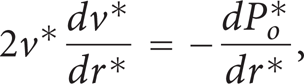
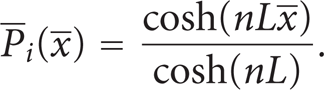
where . For situations where as for micropins applications, the left side of (2) can be ignored. As such, the solutions of (1) and (2) are given by
where and . By substituting (7) and (8) in (2), it is noticed that (7) and (8) are valid when . The inner Nusselt number is equal to
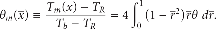
where hi and θm are the inner convection heat transfer coefficient and the inner fluid dimensionless mean bulk temperature, respectively. is the local heat flux between the pin inner surface and the internal flowing fluid. Tm is the mean bulk temperature at a given cross-section. θm can be computed from the following equation:
Schematic diagram for a permeable hollow-pin with suction flow at the outer surface and the corresponding coordinates system.
2.1.1. Integral Energy Equation of the Internal Fluid Flow
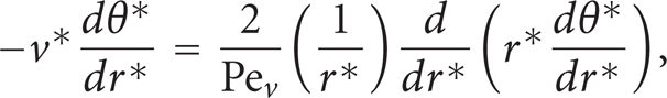
The integral form of (3) can be expressed in the following form:
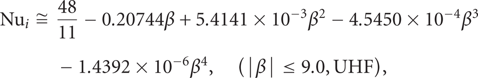
Under Uniform Heat Flux (UHF) condition at the pin inner surface, (3) under fully developed condition can be approximated by
where . If the initial estimate of is taken as , then the fifth iteration resulted from solving (13) produces the following approximation of the Nusselt number:
where . When the pin inner surface has constant surface temperature denoted by CWT-condition, (3) at fully developed condition is approximated by
If the initial estimate of is taken as , then the fourth iteration obtained from solving (15) reveals the following Nusselt number correlation:
2.2. Modeling of Momentum and Heat Transfer outside the Permeable Hollow-Pin
The continuity, momentum, and energy equations for the induced flow outside the pin have the following dimensionless forms:
where
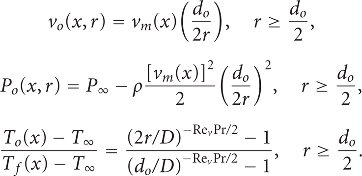
where vm, vo, and To are the fluid averaged normal velocity at the pin outer surface ( with external suction flow), outer stream normal velocity component, and the outer fluid temperature field, respectively.
The boundary conditions of (17) and (18) are given by
when , the outer fluid is being sucked into the permeable hollow-pin internal fluidic volume. However, the inner fluid is blown to the permeable pin external fluidic medium when . The boundary conditions (19) are taken to be
where D is the average diameter of the surrounding boundary. Equations (21a), (21b), (21c), (22a), and (22b) necessitate that the boundaries of the surroundings are isothermal and permeable. The solutions of (17)–(19) are given by
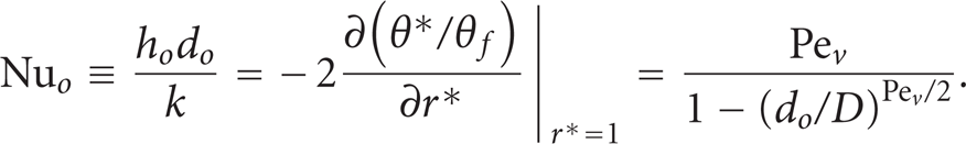
The outer convection heat transfer coefficient ho is defined as where is the local heat flux between the pin outer surface and the external fluid flow. It can be obtained using the outer Nusselt number relationship given by
2.3. Modeling of the Internal Flow Pressure Gradient
Assuming Poiseuille's flow [24] inside the pin pores, the mean velocity inside the pores denoted by vp is given by
The mean velocity inside the pores averaged over the outer surface area is equal to
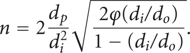
where is the ratio of the pin pores cross-sectional area to total hollow-pin inner surface area. In a dimensionless form, (26) can be rewritten as
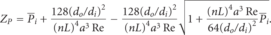
where ZP and n (index number of the induced flow) are equal to
which can be approximated by the following expression:
Equation (30) is obtained by eliminating the fourth term and above of the MacLaurin series [25] of the square root term, . By solving (30) for vm, the following expression can be obtained:
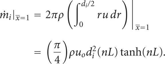
The gradient of the mass flow rate inside the pin can be shown to be equal to the following using the conservation of mass principle as follows:
By utilizing (7) and (27) and the definition of the n-index, (32) can be reduced to the following:
The following boundary conditions of (33) are considered:
The boundary condition given by (34a) necessitates that the pin tip is isolated against mass flux. As such, the solution of (33) is equal to
The condition for validity of (7) and (8) changes to . The total mass flow rate at the pin base is calculated from the following equation:
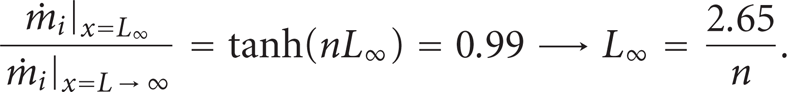
The effective length, L∞, of the pin that causes the mass flow rate at the base to be 99% of the maximum possible mass flow rate, , is obtained by solving the following equation:
2.4. Modeling of Heat Transfer through the Solid Part of the Permeable Hollow-Pin
The one-dimensional energy equation for the solid part of the hollow-pin can be written as
The axial conduction heat transfer rate through the solid part of the hollow-pin can be shown to be equal to
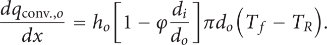
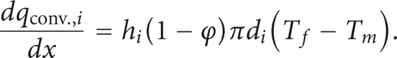
Note that the conduction heat transfer rate across the pores is neglected compared to the conduction rate through the solid part of the hollow-pin as . The second term in the square bracket of (39) represents the ratio of pores volume to the total volume of the permeable hollow-pin. The convection heat transfer rate per unit length between the hollow-pin outer surface and external fluid flow is equal to
The convection heat transfer rate per unit length between the hollow-pin inner surface and internal fluid flow is given by
The convection heat transfer rate per unit length between the pores solid surfaces and the fluid flow inside the pores can be shown to be equal to
By utilizing (39)–(42), (38) can be expressed in dimensionless form as
The boundary conditions for (43a) and (43b) are taken as:
2.4.1. Constraint Averaged Energy Equation of the Permeable Hollow-Pin
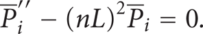
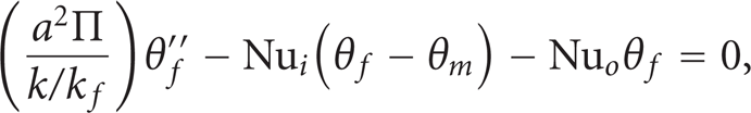
For slender hollow-pin , (43b) with coefficients evaluated at their averaged independent variables is reducible to
Based on correlations given by (14) and (16), the previous constraint requires that . The solution of (45) under conditions given by (44) is
2.5. The Permeable Hollow Joint-Pin
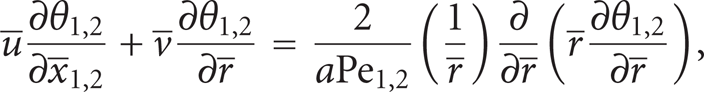
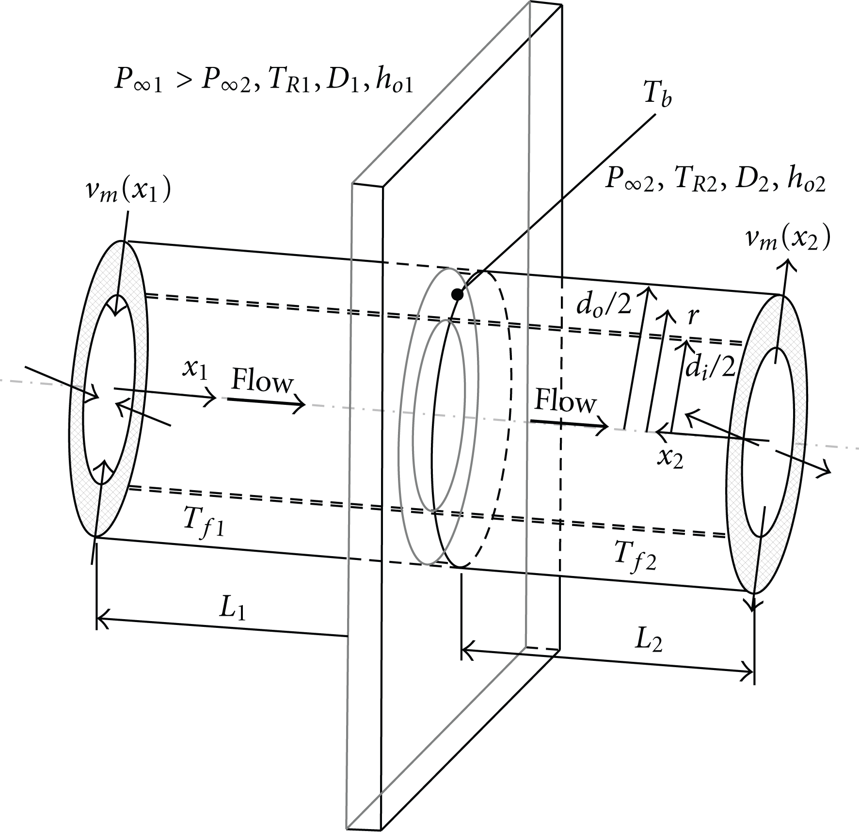
Consider that the permeable hollow-pin discussed in Section 2.1 is joining two different reservoirs of same fluid as shown in Figure 2. The left reservoir has an external free stream pressure and surrounding temperature while the external free stream pressure and the surrounding temperature of the right reservoir are and , respectively. The energy equations for the resulting permeable hollow joint-pin system are
where the dimensionless variables , , , , , and are given by
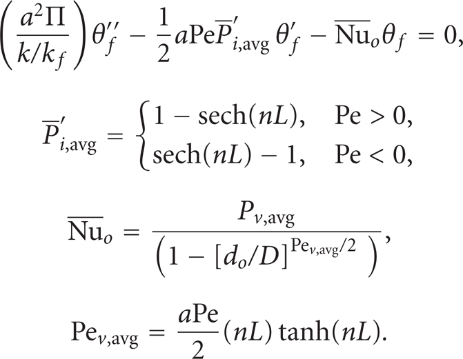
, , , and are the left side joint-pin length, right side joint-pin length, left side inner fluid temperature, and the right side inner fluid temperature, respectively. and are the left side solid part temperature and the right side solid part temperature, respectively. By using the conservation of mass principle and (36), , , , , and the total mass flow rate across the permeable hollow joint-pin can be shown to be equal to
where and Ret are defined as
and are obtained from (24) by replacing with and , respectively. Representative values of outer Nusselt numbers and can be obtained by substituting the average values of and given in (51c) and (51d) in (24). The boundary conditions of (47) are given by
The boundary conditions of (48) and (49) are given by
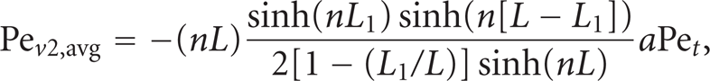
The maximum value of mass flow rate via the permeable hollow joint-pin is evaluated by differentiating (51e) and equating it to zero. It is equal to
Schematic diagram for a permeable hollow joint-pin and the corresponding coordinates system.
2.6. The Thermal Efficiency of the Permeable Hollow-Pin Systems
The maximum heat transfer rate by the permeable hollow-pin, qmax, obtained at is equal to
The total heat transfer rate through the permeable hollow-pin can be obtained from
The thermal efficiency of this type of systems, η, is defined as the ratio of the total heat transfer rate by the permeable hollow-pin to the maximum heat transfer rate. It can be expressed as follows:
In case of the permeable hollow joint-pin, the thermal efficiency is obtained using (57) with Nusselt numbers, dimensionless temperatures, and -coordinate computed for one side of the joint-pin. For the constraint solution given by (46), the thermal efficiency is equal to
2.7. The Second HTE Factor for the Permeable Hollow-Pin Systems
Define the second HTE factor, γ, as the ratio of the system total heat transfer rate to the heat transfer rate from a solid pin of diameter do. Mathematically, it is equal to
where and are the solid pin cross-sectional area and the perimeter of the solid pin, respectively. The outer convection heat transfer coefficient is obtained from (24) at zero Rev, . By substituting (56) in (58), the following expression is obtained:
In case of the permeable hollow joint-pin, the γ-factor is obtained using (60) with Nusselt numbers, dimensionless temperatures, -coordinate, a-ratio, and D-diameter computed for one side of the joint-pin. When , the performance of the permeable fin is better than that of the solid one. However, the performance of the solid pin is better than that of permeable fin when .
3. Numerical Methodology and Validations
3.1. Numerical Methodology
Equations (3), (43a), (43b), or (47)–(49) are coupled via the boundary conditions and must be solved using an iterative numerical method. The implicit finite-difference method that Blottner [26] discussed is an appropriate and an accurate numerical method for the present problem. This method is based on discretizing the second derivatives terms using three-point central different quotients. Also, the first derivative term with respect to -direction is discretized using the three-point central different quotient. Two-point backward differencing quotient is considered for the first derivative with respect to -direction. The resulting tridiagonal systems of algebraic equations obtained by the discretization process at a given -section were solved using the well-established Thomas algorithm [26]. The same procedure was repeated for the consecutive -sections until , when . When , the marching of the numerical method was started at and the previous procedure was repeated for the consecutive sections until . After that, the values of θm or were calculated using (10). Then, the discretized system of equations was solved again using the Thomas algorithm for the second iteration. Next, the previous procedure was periodically repeated by updating the values of θf or until the maximum change in θm or between the current and previous iterations be less than .
3.2. Validations
When , both θf and θm increase as increases. Thus, given by (14) can substituted in (11), (43a), and (43b). On the other hand, correlation given by (16) is the most appropriate correlation to be used when . For both situations, the coupled equations (43a), (43b), and (11) are one-dimensional equations which can be solved using an iterative numerical method based on the Thomas algorithm. The comparisons between the present numerical solutions (approximate solutions) and the two dimensional numerical solutions discussed in Section 3.1 are shown in Figures 3–10. Meanwhile, the comparison between the highly constraint solution given by (58) and the two-dimensional solution under the same constraint is shown in Figure 3. Very good agreements are noticed between all solutions. This led to more confidence in the obtained results.
Effects of Pe and on η when both and .
Effects of Pe and on γ when both and .
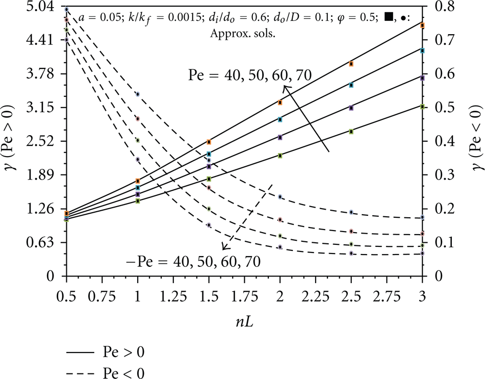
Effects of nL and Pe on γ when both and .
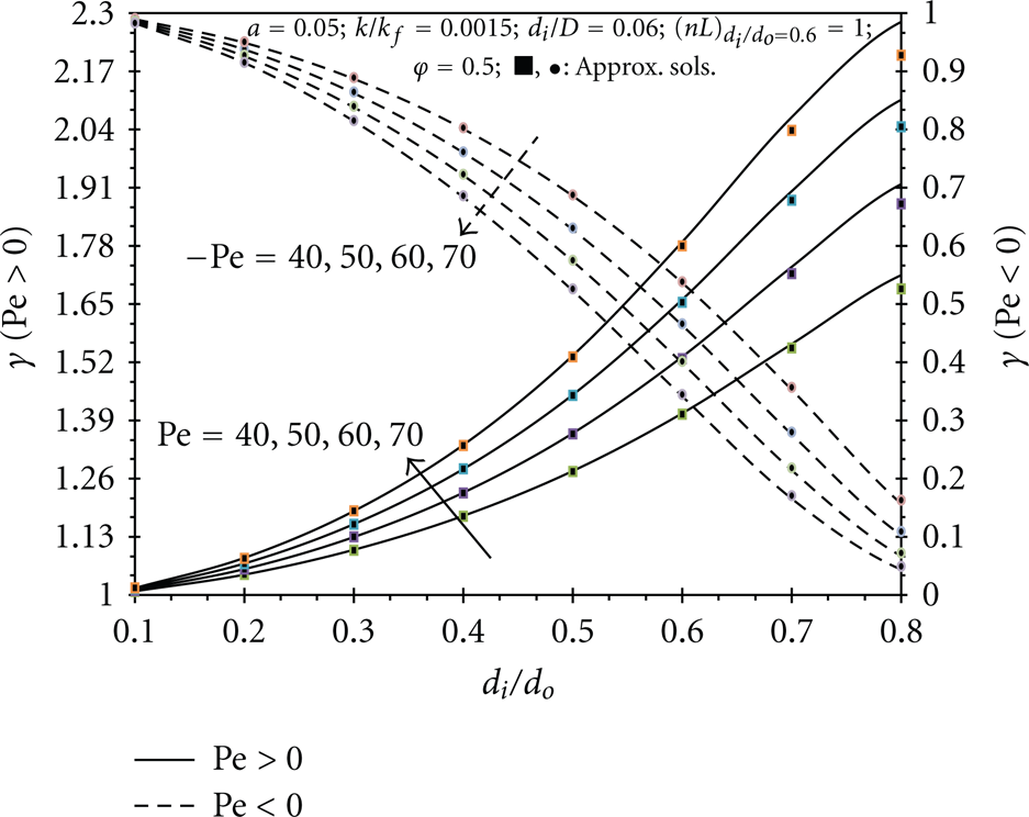
Effects of and Pe on γ when both and .
Effects of φ and Pe on γ when both and .
Effects of and on η and γ for permeable hollow joint-pin.
Effects of and nL on η and γ for permeable hollow joint-pin.
Effects of and φ on η and γ for permeable hollow joint-pin.
4. Results and Discussions
4.1. The Performance of the Hollow-Pin due to Variation in the Peclet Number
Figure 3 shows the variation of the thermal efficiency of the permeable hollow-pin with the Peclet number for different values of fluid to pin (solid part) thermal conductivities ratio . When , the permeable pin temperatures near the tip region are furtherly convected toward the base region as Pe increases. This effect tends to increase the heat transfer rate at the base which increases the thermal efficiency. However, the outer convection coefficient increases as Pe increases when due to increases in the suction effects at the outer surface. The latter effect tends to decrease the thermal efficiency. Due to the previous effects, the thermal efficiency is maximized at a specific Pe value when . When , the permeable pin temperatures near the base region are furtherly convected toward the tip region as increases. Furthermore, ho-coefficients decreases as increases due to increases in the blowing effects. Both effects decrease the heat transfer rate through the permeable pin. Thus, the thermal efficiency decreases as increases when . Increasing the pin thermal conductivity which decreases causes increases in the heat transfer rate, the thermal efficiency and the second HTE factor . These trends are shown in Figures 3 and 4, respectively. It is shown from Figure 4 that γ increases as Pe increases when while it decreases as increases when . This is because the increase in causes an increase in the heat transfer rate when due to increases in both ho-coefficients and temperature gradients near the base. However, the increase in causes a decrease in the heat transfer rate when due to increases in blowing effects as increases. Figure 4 shows that when while it is when . This indicates the superiority of the permeable hollow-pin with external suction flow over those with external blowing flow.
4.2. The Performance of the Hollow-Pin due to Variation in Flow Index Number
Figure 5 illustrates the variation of the second HTE factor of the permeable hollow-pin with the induced flow index number for different Peclet numbers. As n increases, the total mass flow rate across the permeable pin increases as dictated from (36). Thus, γ increases as n increases when due to increases in suction effects. However, γ decreases as n increases when due to increases in blowing effects at the outer surface. These trends are clearly seen in Figure 5. Moreover, Figure 5 shows that for large n numbers, the γ-factor becomes more sensitive to variation in the Peclet numbers. Figure 5 shows that maximum value of γ is γ = 4.62. Figure 5 shows that HTEs due to permeable hollow-pins is only present when as for this case.
4.3. The Performance of the Hollow-Pin due to Variation in
Figure 6 displays the effect of permeable hollow-pin inner to outer diameters ratio on the second HTE factor for different Peclet numbers. The change in is obtained by varying the outer diameter do under same inner diameter di. An increase in do causes a decrease in n-index (see (28b)) thus, convection heat transfer rate is reduced when . The latter effect can be explained using (24), (31), and (40). As such, γ-factor decreases as do increases or as decreases. On the other hand, the blowing effect at the pin outer surface when is reduced when n-index decreases. Therefore, γ-factor increases as do increases or as decreases. These trends are clearly shown in Figure 6. Moreover, Figure 6 shows that for large ratios, the γ-factor becomes more sensitive to variation in the Peclet number. Furthermore, Figure 6 shows that HTEs due to permeable hollow-pins is only present when .
4.4. The Performance of the Hollow-Pin due to Variation in φ-ratio
Figure 7 shows the effect of φ-ratio on the second HTE factor of the permeable hollow-pin for different Peclet numbers. An increase in φ-ratio produces an increase in n-index (see (28b)), thus, convection heat transfer rate is increased when as explained earlier. In addition, the increase in φ-Ratio decreases conduction heat transfer through the pin due to reduction of the higher thermal conductivity volume (the solid volume). Due to these reasons, γ is maximized at a specific φ-ratio as can be seen from Figure 7. On the other hand, the blowing effect at the pin outer surface increases as φincreases when due the associated increase in n-index. Therefore, γ-factor decreases as φ increases when . This is shown in Figure 7. Moreover, Figure 7 shows that for large φ-ratios, γ-factor becomes more sensitive to variation in the Peclet numbers. Figure 7 shows that HTEs due to permeable hollow-pins is only present when .
4.5. The Performance of the Permeable Hollow Joint-Pin
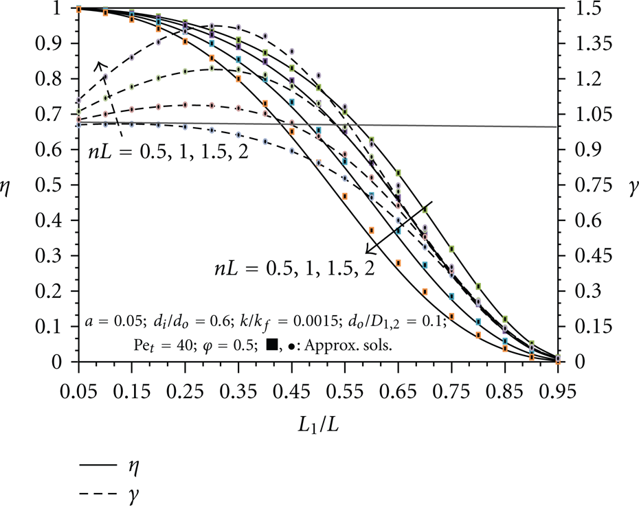
Figures 8–10 illustrate the effect of the relative lengths ratio on the thermal efficiency and γ-factor of the permeable hollow join-pin for different total Peclet numbers, n-indices, and φ-ratios, respectively. As increases, the average outer Nusselt number decreases which in turn is much smaller than . This effect requires an increase in the departure of the base temperature Tb from thus, the heat transfer rate decreases. Meanwhile, an increase in decreases the thermal efficiency of the joint-pin left portion due to an increase in its conduction resistance. Due to the previous reasons, the thermal efficiency of the joint system is expected to decrease as increases as shown in Figures 8–10. An increase in , nL, or φ causes a further reductions (e.g., see Figure 11) and the left side conduction resistance relative to its outer convection resistance. As such, it causes further reduction in the thermal efficiency as shown in Figures 8–10. Since both the flow rate through the permeable hollow joint-pin and the overall average outer Nusselt number are maximized at as illustrated in (53a), (53b), (53c), and Figure 11, respectively. It is expected that γ-factor must be maximized at specific -value. This is illustrated in Figures 8–10. This specific value is expected not to coincide with due to the following factors: (a) the increase in conduction resistance in permeable hollow joint-pins due to presence of fluid volumes, (b) the variation of inner convection resistance across the two sides of system, and (c) the presence of entry region effects near the base section on the right side of the system. An increase in , nL, or φ causes further increases in (e.g., see Figure 11). As such, it causes a further increase in γ-factor as seen in Figures 8–10. Figure 9 shows that maximum value of γ is γ = 1.44.
Effects of and nL on , , and for permeable hollow joint-pin.
5. Conclusions
In this work, flow and heat transfer through permeable hollow-pin systems were studied. Two different systems are considered: (A) the permeable hollow-pin system, and (B) the permeable hollow joint-pin system. Numerous mathematical techniques were used to model flow and energy transport in the explored systems. The appropriate dimensionless forms of the governing equations were solved using a well-known finite-difference numerical method. Very good agreements were obtained between the results of numerical solutions and the many analytical solutions derived in this work. The following main findings were found.
Enhancing of heat transfer in a permeable hollow-pin over that of the solid pin is only reachable when an external suction flow is present at the hollow-pin outer surface.
Enhancing of heat transfer in a permeable hollow joint-pin over that of a solid joint-pin can be attained at a specific hollow joint-pin relative lengths ratio.
Factors increasing both the internal fluid flow and the conduction through the solid parts of the permeable hollow-pin and permeable hollow joint-pin systems tend to further enhance the heat transfer rate. Examples of these factors are the pores diameter and the thermal conductivity of the solid parts.
The maximum reported heat transfer rate due to permeable hollow-pin is 362 percent above that of solid pin at dimensionless suction number equal to 3.0.
The maximum reported heat transfer rate due to permeable hollow joint-pin is 44 percent above that of solid joint-pin at dimensionless suction number equal to 2.0.
Finally, this work demonstrates that using combined heat transfer enhancement approaches is capable of attaining an accumulated enhancement levels.
Footnotes
Nomenclature
Greek Symbols
Subscripts
References
1.
GoldsteinR. J.IbeleW. E.PatankarS. V., “Heat transfer-a review of 2003 literature,”International Journal of Heat and Mass Transfer, vol. 49, no. 3–4, pp. 451–534, 2006.
2.
GoldsteinR. J.IbeleW. E.PatankarS. V., “Heat transfer-a review of 2004 literature,”International Journal of Heat and Mass Transfer, vol. 53, no. 21–22, pp. 4343–4396, 2010.
3.
GoldsteinR. J.IbeleW. E.PatankarS. V., “Heat transfer-a review of 2005 literature,”International Journal of Heat and Mass Transfer, vol. 53, no. 21–22, pp. 4397–4447, 2010.
4.
KimK. Y. and ChoiJ. Y., “Shape optimization of a dimpled channel to enhance turbulent heat transfer,”Numerical Heat Transfer Part A, vol. 48, no. 9, pp. 901–915, 2005.
5.
MetwallyH. M. and ManglikR. M., “Enhanced heat transfer due to curvature-induced lateral vortices in laminar flows in sinusoidal corrugated-plate channels,”International Journal of Heat and Mass Transfer, vol. 47, no. 10–11, pp. 2283–2292, 2004.
6.
StephanR. A. and TholeK. A., “Optimization study relevant to louvered fin compact heat exchangers,”International Journal of Heat Exchangers, vol. 6, no. 1, pp. 73–92, 2005.
7.
ChengY. P.QuZ. G.TaoW. Q., and HeY. L., “Numerical design of efficient slotted fin surface based on the field synergy principle,”Numerical Heat Transfer Part A, vol. 45, no. 6, pp. 517–538, 2004.
8.
LinC. W. and JangJ. Y., “3D Numerical heat transfer and fluid flow analysis in plate-fin and tube heat exchangers with electrohydrodynamic enhancement,”Heat and Mass Transfer, vol. 41, no. 7, pp. 583–593, 2005.
9.
BuffoneC.SefianeK.BuffoneL., and LinS., “Heat transfer enhancement in heat pipe applications using surface coating,”Journal of Enhanced Heat Transfer, vol. 12, no. 1, pp. 21–35, 2005.
10.
YangY.ZhangZ. G.GrulkeE. A.AndersonW. B., and WuG., “Heat transfer properties of nanoparticle-in-fluid dispersions (nanofluids) in laminar flow,”International Journal of Heat and Mass Transfer, vol. 48, no. 6, pp. 1107–1116, 2005.
11.
SiddiqueM.KhaledA. R. A.AbdulhafizN. I., and BoukharyA. Y., “Recent advances in heat transfer enhancements: a review report,”International Journal of Chemical Engineering, vol. 2010, Article ID 106461, 28 pages, 2010.
12.
ChamkhaA. J. and KhaledA. R. A., “Hydromagnetic combined heat and mass transfer by natural convection from a permeable surface embedded in a fluid-saturated porous medium,”International Journal of Numerical Methods for Heat and Fluid Flow, vol. 10, no. 5, pp. 455–476, 2000.
13.
AliM. and Al-YousefF., “Laminar mixed convection boundary layers induced by a linearly stretching permeable surface,”International Journal of Heat and Mass Transfer, vol. 45, no. 21, pp. 4241–4250, 2002.
14.
WangS. C.ChenC. K., and YangY. T., “Natural convection of non-Newtonian fluids through permeable axisymmetric and two-dimensional bodies in a porous medium,”International Journal of Heat and Mass Transfer, vol. 45, no. 2, pp. 393–408, 2001.
15.
HassanienI. A.EssawyA. H., and MoursyN. M., “Natural convection flow of micropolar fluid from a permeable uniform heat flux surface in porous medium,”Applied Mathematics and Computation, vol. 152, no. 2, pp. 323–335, 2004.
16.
AydinO. and KayaA., “Laminar boundary layer flow over a horizontal permeable flat plate,”Applied Mathematics and Computation, vol. 161, no. 1, pp. 229–240, 2005.
17.
KhaledA. R. A.RadhwanA. M., and Al-MuaikeS. A., “Analysis of laminar falling film condensation over a vertical plate with an accelerating vapor flow,”Journal of Fluids Engineering, Transactions of the ASME, vol. 131, no. 7, Article ID 071304, 2009.
18.
Abu-HijlehB. A. K., “Enhanced forced convection heat transfer from a cylinder using permeable fins,”Journal of Heat Transfer, vol. 125, no. 5, pp. 804–811, 2003.
19.
Abu-HijlehB. A. K., “Natural convection heat transfer from a cylinder with high conductivity permeable fins,”Journal of Heat Transfer, vol. 125, no. 2, pp. 282–288, 2003.
20.
KhaledA. R. A., “Investigation of heat transfer enhancement through permeable fins,”Journal of Heat Transfer, vol. 132, no. 3, Article ID 034503, pp. 1–5, 2010.
21.
KiwanS. and Al-NimrM. A., “Using porous fins for heat transfer enhancement,”Journal of Heat Transfer, vol. 123, no. 4, pp. 790–795, 2001.
22.
KhaledA. R. A., “Thermal characterizations of fin-thin film systems,”Journal of Heat Transfer, vol. 132, no. 10, Article ID 104503, 6 pages, 2010.
23.
KhaledA. R. A., “Heat transfer enhancement using pin-finsporous-media systems,”Journal of Porous Media, vol. 14, no. 12, pp. 1059–1075, 2011.
24.
SuteraS. P. and SkalakR., “The history of Poiseuille's law,”Annual Review of Fluid Mechanics, vol. 25, no. 1, pp. 1–19, 1993.
25.
GreenbergM., Advanced Engineering Mathematics, Prentice Hall, New York, NY, USA, 2nd edition, 1998.
26.
BlottnerF. G., “Finite-difference methods of solution of the boundary-layer equations,”AIAA Journal, vol. 8, pp. 193–205, 1977.