
Abstract
Over the last few years, we have witnessed a growing interest in cyber physical systems (CPSs) that rely on a strong synergy between computational and physical components. CPSs are expected to have a tremendous impact on many critical sectors (such as energy, manufacturing, healthcare, transportation, and aerospace) of the economy. CPSs have the ability to transform the way human-to-human, human-to-object, and object-to-object interactions take place in the physical and virtual worlds. The increasing pervasiveness of wireless sensor networking (WSN) technologies in many applications makes them an important component of emerging CPS designs. We present some of the most important design requirements of CPS architectures. We discuss key sensor network characteristics that can be leveraged in CPS designs. In addition, we also review a few well-known CPS application domains that depend on WSNs in their design architectures and implementations. Finally, we present some of the challenges that still need to be addressed to enable seamless integration of WSN with CPS designs.
1. Introduction
Recent advances in wireless communications, networking, and embedded system technologies have led to a growing interest in developing Cyber Physical Systems (CPSs) for various purposes. In recent years, the CPS has emerged as a promising technology that can support the human-to-human, human-to-object, and object-to-object interactions in the physical and virtual worlds.
A CPS is the integration of abstract computations and physical processes [1–3], where sensors, actuators, and embedded devices are networked to sense, monitor, and control the physical world. In contrast to traditional embedded systems, the CPS is a network of interacting appliances with physical inputs and outputs instead of standalone devices. A typical CPS application is to connect appliances embedded with sensor nodes (which are responsible for information collection from the physical world as the source of CPS inputs) to some real-time decision making system (which represents the virtual world). Upon receiving the inputs from sensor nodes, the CPS will make a corresponding decision based on the inputs and computational processing to the actuators in the physical world by a sequence of control processes. We summarize below four major features of CPSs [3].
The first feature of CPS is the integration of appliances with different communication protocols. The appliances in the physical world might adopt different communication protocols such as WiFi, Bluetooth, Zigbee, RF, infrared and so on. The CPSs could integrate these appliances into one network. The second feature is the rapid change of network topology. Some wearable sensors might be worn by people. As a result, the network topology dynamically changes with the movements of people. The third feature is remote Internet access. Each appliance in a CPS application must have the capability to access the Internet. Based on this capability, the real-time decision making system which is part of the CPS could successfully receive available CPS inputs from appliances and then makes decisions to control the physical world. The fourth feature is the real-time constraint for some delay-sensitive applications such as applications of healthcare and emergency real-time systems. If this constraint is not achieved, such delay-sensitive applications might become unreliable and unusable.
The CPS technology could efficiently manage, monitor, and indeed control the physical world. Consequently, many CPS applications are being proposed currently. These applications can be roughly classified into smart space, healthcare, emergency real-time system, environmental monitoring and control as well as smart transportation.
For a smart space application, many daily activities can be performed more intelligently and conveniently by the interactions between the physical world and the virtual world. A healthcare application could acquire vital signs by medical sensors worn by patients or elders. The acquired data can then be used by some real-time decision making system to determine the appropriate actions that need to be taken. An emergency real-time system could not only help people avoid unpredictable disasters (such as tsunami, volcanic eruptions or mudslide) but can also provide potential escape solutions for people. As a result, life would be safer and more secure. In the case of environmental monitoring and control applications, sensor nodes might be deployed in the outdoor environments to monitor soil moisture, air quality, and so forth. When certain specific events occur, the real-time decision making system can send commands to actuators to execute the corresponding tasks. For example, when a humidity sensor detects that the soil is too dry, the real-time decision making system will send commands to an actuator to water the dry soil. Smart transportation is one of the most important CPS applications. Sensor nodes (such as accelerometer and GPS receiver) could be embedded in vehicles to improve the traffic safety and efficiency. For instance, the accelerometer can be used to detect the potholes on the road. When a pothole is detected by an accelerometer embedded in a vehicle, the vehicle will send the location information (which is obtained by a GPS receiver) about this pothole to its nearby vehicles, hence improving the traffic safety and efficiency.
For all the aforementioned applications, Wireless Sensor Network (WSN) technology is an integral component of CPS designs. If WSN technology is not used in the development of CPSs, the real-time decision making system might have difficulty in acquiring available CPS inputs and making timely decisions. As a result, the CPS designs would be unreliable and unpredictable. It is our hope that the results of this work will help designers and researchers of CPSs to improve the reliability and predictability of such systems using sensor networking technologies.
In the next section, we present the design of a CPS architecture and the major requirements of CPSs. In Section 3, we briefly present the design of a typical sensor node architecture. We review the five fundamental WSN characteristics (such as deployment, localization, coverage, etc.) that can be leveraged in CPS designs in Section 4. In Section 5, we present a survey of well-known CPS applications from different domains and highlight their key characteristics. We discuss some of the design challenges of CPSs in Section 6. Finally, Section 7 makes some concluding remarks.
2. Cyber Physical Systems
This section presents the basic features and requirements of a typical CPS architecture.
2.1. CPS Architecture
The CPS is similar to the traditional embedded system, which aims to combine the physical processes with abstract computations. However, unlike traditional embedded systems, the CPS is a network of interacting appliances with physical inputs and outputs instead of standalone devices.
Figure 1 illustrates the architecture of a CPS which is mainly composed of physical layer and virtual layer. At the physical layer, sensors and actuators are responsible for information collection and controlling the physical world, respectively. In addition, the different types of collected information by sensors are also converted from the analog format into the digital format in this layer, and then sent to the virtual layer as the CPS inputs of the real-time decision making system. In the virtual layer, upon receipt of the inputs, the decision making system executes the abstract computations to analyze the collected data and then relays its decision to the actuators in the physical world by a sequence of control processes.

The CPS architecture.
For example, as shown in Figure 2, Correll et al. [4] develops a distributed autonomous gardening system, where gardening robots and plants are networked by sensors and actuators. Robots which are all mobile actuators are capable of locating and watering plants in the garden. In addition, each plant is equipped with a humidity sensor to monitor the soil moisture. When a humidity sensor detects that the soil is too dry, it sends a request to the decision making system. Upon receiving the request, the system sends a command to a robot to water the dry soil through a sequence of control processes.
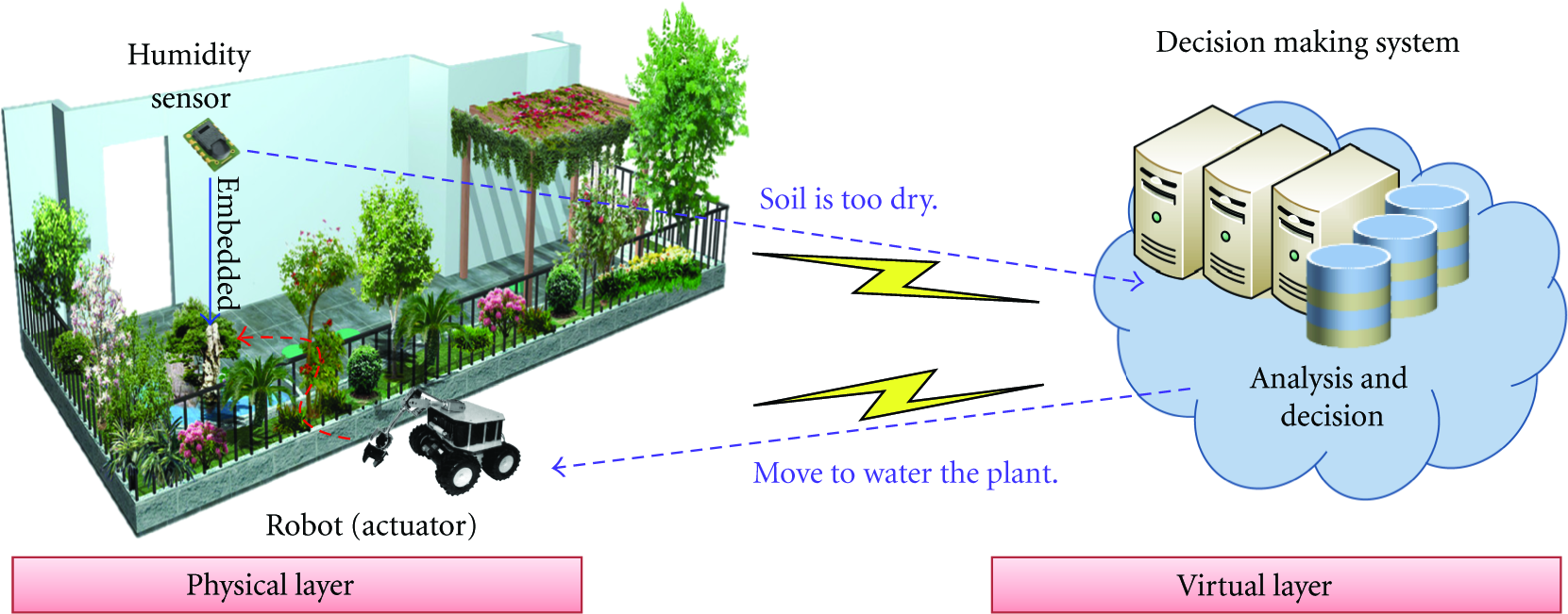
The distributed autonomous gardening system.
2.2. Design Requirements for CPS Architectures
Reliability and predictability are two important requirements in CPS designs [1–3]. This is because the quality of service (QoS) of CPS applications, such as emergency real-time system and healthcare, highly depends on these two factors. When sensor technologies are integrated with CPSs, it is a challenge for the decision making system to ensure reliability and predictability.
Deployment involves how to place sensor nodes over the given monitoring region in an efficient way while localization approach aims at providing location information for sensor nodes. Any coverage method requires that the region of interest (ROI), where the interesting events might happen, has to be covered by sensors. A data gathering scheme ensures that the collected information can be successfully delivered from sensors to the sink node (which can be treated as the real-time decision making system). Moreover, to ensure the negotiation of any two neighboring sensors and to conserve the energy consumption, the communication (Medium Access Control) support should also be considered in CPS designs.
3. Wireless Sensor Node Architecture
This section describes the hardware architecture of a wireless sensor node. We then introduce several popular sensor node platforms available today.
3.1. Sensor Node Architecture
The wireless sensor node is a device that converts the various measurement metrics used for physical, chemical, biomass quantities and so on in the physical world into digital information which can be read and identified by a user or by an instrument. Figure 3 illustrates the sensor node architecture, which is mainly composed of four basic components, namely sensing unit, processing unit, transceiver unit, and power unit [5].

The hardware architecture of a wireless sensor node.
The sensing unit consists of two subunits: the sensor and the Analog to Digital Converter (ADC). The sensor subunit is responsible for information collection from the physical world. There are many kinds of sensors currently in use in many areas of daily life. For example, temperature and humidity sensors are used to detect the temperature and humidity in the air, respectively, while light sensor can measure the intensity of the light. In addition to the sensor subunit, the ADC is used to convert the analog signals produced by sensor subunit into digital signals which are then sent to the processing unit of a sensor node.
The processing unit consists of two subunits: the memory and the processor. Similar to the storage device such as the hard disk of the host, the memory subunit is employed to store the information collected by sensing unit and is operated by the firmware. Moreover, the tasks of the processor subunit, which is similar to the central processing unit (CPU) of the host, are to execute the instructions stored in the memory subunit in addition to managing and coordinating all units.
The transceiver unit and power unit are both important components of a sensor node. Since sensor nodes might be deployed over a large-scale outdoor environment, it is difficult to use the wired transmissions to communicate with their neighbors. Moreover, replacing sensor nodes is difficult for certain applications when some nodes exhaust their energy. To cope with these two constraints, each sensor node is equipped with both transceiver and power units. The transceiver unit ensures that each sensor node can communicate with its neighbors via wireless communications while the power unit is used to manage and allocate the power resource. In general, the power source of a sensor node is usually based on batteries.
In addition to the aforementioned sensing, processing, transceiver, and power units, a sensor node might additionally have some specific components, such as the Global Positioning System (GPS), motor, and power generator units (as shown in Figure 3). The GPS unit can help a sensor node acquire its own location information while the motor unit offers a sensor node movement capability. The power generator unit is responsible for power generation by applying some specific technique such as solar cell.
3.2. Popular Sensor Node Platforms
This subsection presents a few popular sensor node platforms. Table 1 shows some key features of these platforms.
Comparison of the popular sensor node platforms.

UC Berkeley's Smart Dust project [6] developed the Commercial Off-The-Shelf (COTS) Dust [7]. The WeC mote is one of the first platforms developed in this project. Based on the WeC mote, an important platform, namely Rene, was developed later and it is also one of the early commercialized platforms produced by Crossbow. The Rene mote later evolved into several popular platforms, including Mica, Mica2, Mica2Dot, and MicaZ.
The Mica platform has a similar performance with WeC and Rene motes in terms of radio robustness since all of them adopt the RFM TR1000 radio transceiver. The Mica platform has more memory (such as 4 KB of RAM, 128 KB of Flash, and 512 KB of EEPROM) than the WeC and Rene motes. In addition, the Mica2 platform is equipped with the Chipcon CC1000 radio transceiver instead of RFM TR1000 and therefore the radio of Mica2 is more robust than that of Mica. In addition to radio robustness, the Mica2 platform has a higher CPU clock than the Mica mote. On the other hand, the Mica2Dot platform is quite similar to the Mica2 mote. The major difference between them is that the size of Mica2Dot is smaller than that of Mica2. However, the performance of Mica2Dot is worse than that of Mica2 in terms of CPU clock. Unlike the aforementioned Berkeley's motes, the MicaZ platform is available in 2.4 GHz and adopts Chipcon CC2420 radio transceiver which results in a satisfactory radio communication. Today, the MicaZ platform is one of the most popular platforms in the world.
The Telos [8] is another famous sensor platform also developed by UC Berkeley. It is designed to minimize power consumption with increased software and hardware robustness as well as ease of use. To achieve these goals, the MSP430 produced by Texas Instruments is selected as the microcontroller of Telos platform. This is because the MSP430 has the lowest power consumption in sleep and active modes compared to the other microcontrollers such as Atmel's AT90LS8535 and Atmega 128L. In addition, the MSP430 microcontroller also offers more memory, which ensures that the complex instructions can be successfully executed and additional hardware accelerator modules can be added. Finally, instead of integrating many different hardware modules into a sensor node, the Telos platform directly combines the programming, computation, communication, and sensing on a single device. This design makes the Telos platform easy to use.
The BTnode platform [9] is based on the Atmel Atmega 128L microcontroller and Zeevo ZV4002 Bluetooth module. Its CPU clock is able to reach 8 MHz and its memory consists of 4 KB of RAM, 128 KB of Flash, and 4 KB of EEPROM. Compared to the Berkeley's motes, the BTnode platform can effectively combine different appliances by a standardized interface and offers higher bandwidth. This is because the BTnode platform adopts the Bluetooth technique. However, it has higher power consumption and requires spending a long time on the connection setup.
The Intel Mote (iMote) [10] is mainly designed for industrial equipment monitoring. Unlike environmental monitoring, industrial monitoring aims to detect some specific measurements such as vibration and acceleration. Consequently, in addition to cost-effectiveness, sensor nodes for this application also need to have satisfactory CPU performance and radio reliability. To this end, the Zeevo ZV4002 is chosen to be the microcontroller of iMote, which adopts an ARM7TDMI core. Since the ZV4002's CPU clock can reach 12 MHz and contains 64 KB of RAM and 512 KB of Flash which provide enough performance to be used for data compression and initial classification and analysis for industrial monitoring applications. Moreover, the Zeevo ZV4002 also incorporates a Zeevo BT radio transceiver which supports the Bluetooth Scatternet technology. The Intel Mote 2 (iMote2) [11] is an advanced platform which is also suitable for industrial equipment monitoring applications. The iMote2 platform is based on the Intel PXA 271 which is a high performance microcontroller with CPU clock ranging between 13 MHz and 416 MHz. Furthermore, the iMote2 has 32 MB of RAM and 32 MB of Flash. In contrast to the iMote mote, the iMote2 platform uses the Chipcon CC2420 radio transceiver which adopts 802.15.4 radio technology instead of Bluetooth.
The popularity of sensor node platforms such as WeC, Rene, Mica, Mica2, Mica2Dot, MicaZ, Telos, BTnode, iMote, and iMote2 motes arises mainly because of their open source feature. In addition, an event-driven real-time operating system, called TinyOS [12], is used on these platforms because of its compactness and simplicity.
4. Key Characteristics of WSNs Used in CPS Designs
As we mentioned earlier, important sensor characteristics that need to be taken into account when we integrate sensor technologies into CPSs include deployment, localization, coverage, data collection, and communication (Medium Access Control). Figure 4 summarizes these characteristics.

The five fundamental WSN technologies which are the bases in CPS designs.
4.1. Deployment
Developing a good deployment approach is necessary in CPS designs. The major objectives of deployment are to ensure the monitoring quality of the ROI and network connectivity. The monitoring quality of the ROI requires that the ROI has to be covered by sensors. The network connectivity ensures that the sensing data can be successfully delivered from each sensor to the sink node. Without an efficient deployment approach, both the monitoring quality and the network connectivity cannot be guaranteed. That is, the decision making system would not successfully receive the available CPS inputs, thereby making it harder to build reliable and predictable CPSs.
This subsection reviews existing few well-known current sensor deployment approaches which can be roughly classified into the categories of fixed sensor [13–19], mobile sensor [20–23], and mobile robot deployments [24–29].
4.1.1. Fixed Sensor Deployment
The fixed sensor deployment approaches can be further classified into manual configuration [13–15] and random deployment schemes [16–19]. The manual configuration approach is suitable for CPS applications which are built in an indoor or a small region environment such as smart space and healthcare applications. This is because the positions of all sensor nodes can manually be determined in accordance with the requirements of the CPS applications. References [13–15] employed a manual configuration approach to deploy fixed sensor nodes over the monitoring region. Manual configuration is one of the simplest ways to deploy sensors. However, this approach is impractical for a large-scale sensor network.
Another fixed sensor deployment approach is the random deployment scheme. Since the fixed sensors can be deployed by a helicopter, an aircraft or other vehicle, the random deployment scheme is quite suitable for a large-scale sensor network. However, to guarantee the monitoring quality and network connectivity, the number of deployed sensors has to be much larger than the number of actual required sensors. This would lead to a redundant node problem, resulting in many redundant sensors in the given monitoring region and leading to a significant hardware cost. To address this problem, various solutions [16–19] which make redundant sensors enter the sleeping mode to save energy were proposed for different WSN applications.
Li and Cassandras [16] consider a target coverage application in a given monitoring region in which a large number of sensors has been randomly deployed. The objective of [16] is to collect data from the given disconnected targets. Hence, there should be at least one sensor active nearby each target to ensure the monitoring quality. In addition, since all disconnected targets might be far from the sink node, a certain number of sensors also need to be active for maintaining network connectivity. In [16], any sensor in the monitoring region falls into one of the four states, including sensing, relaying, sleeping, and dead states. A sensor which falls into a sensing state should be responsible for target monitoring while a sensor in relaying state is only responsible for data relaying. When a sensor stays in the sleeping state, it does not need to participate in either monitoring or relaying tasks and enters sleeping mode to conserve its energy. A sensor falls into a dead state when it has been exhausted its energy and is no longer available to the given WSN. To address the redundant node problem and reduce the total energy consumption of sensors, the solution proposed in [16] aims at minimizing the number of sensors belonging to sensing and relaying states.
C
Gupta et al. [18] dealt with the data gathering issue in a WSN consisting of many randomly deployed sensors. Since sensors that are close enough might contribute the same or similar sensing data, to reduce the total energy consumption of sensors, the authors in [18] proposed one centralized and two distributed algorithms to construct a topology which consists of a subset of sensors located in the monitoring region. Only sensors involved in the constructed topology are responsible for relaying data while the other nodes enter the sleeping mode to conserve energy.
In [19], the authors also considered the data gathering issue in a randomly deployed WSN. In contrast to [18], C. Y. Chang and H. R. Chang [19] further took into account the factor of energy balancing. First, a topology construction protocol was proposed to construct a balanced data collection tree which is rooted by the sink node. Based on this protocol, the number of sensors in the left subtree and the number of sensors in the right subtree differ slight, thereby balancing the delay time for data collection. Subsequently, two node-placement techniques were proposed. Depending on the transmission loads of sensors, the two proposed schemes can be used to balance the energy consumptions of sensors. Finally, a collision-free Medium Access Control (MAC) scheduling protocol was presented to prevent collisions of packets and to further minimize the total energy consumption and delay time.
This subsection mainly introduces proposed random deployment schemes for fixed sensor deployments. Compared to the mobile sensor deployment and mobile robot deployment schemes, the random deployment approach is simpler and easier to implement. Nevertheless, the redundant node problem is still a challenge in such deployment approaches and needs to be overcome using novel solutions.
4.1.2. Mobile Sensor Deployment
The mobile sensor deployment approach is suitable for some CPS applications such as the applications of military, ecological monitoring and volcanic eruption monitoring, where the monitoring region might be too dangerous for people to reach. Therefore, using the mobility of sensor nodes to guarantee the monitoring quality and network connectivity is a good policy.
References [20–23] considered the deployment issue in a mobile WSN, where each sensor has movement capability. In the mobile sensor deployment approach, to ensure the monitoring quality and network connectivity, each mobile sensor calculates their next target location based on the information about the coverage holes. Then, it moves to the calculated target location to heal the hole. Hereafter, the coverage hole denotes the area where none of sensors' sensing ranges covers this area.
Reference [20] studied the deployment issue in a mobile WSN. The objective of [20] is to maximize the size of the area covered by mobile sensors while minimizing the movement distance of each mobile sensor. To achieve this goal, Chellappan et al. [20] translated the sensor node deployment problem into a weighted virtual graph. In the graph, the vertex set contains the areas in the given monitoring region while the edge set contains the possible sensor movement paths between areas. In addition, the capacities for edges model the number of sensors which can move between areas. A cost value is also assigned to each edge to capture the number of movements between areas. Based on the constructed virtual graph, the goal of maximizing the size of the area covered by mobile sensors becomes how to efficiently determine flows to the hole vertices in the graph.
Heo and Varshney [21] proposed three distributed energy-efficient deployment algorithms for mobile sensors. The first scheme operates in a peer-to-peer environment where all sensors are fairly important. Consider a mobile sensor s. The basic concept of the first scheme is to calculate the partial forces between sensor s and all its neighbors according to sensor s's location and the local density. Then, the resultant force can be derived by the calculated partial forces. As a result, sensor s can determine its movement direction based on the resultant force. The second algorithm combines the first peer-to-peer scheme with one of the current cluster-based methods. The cluster-based method, which uses a hierarchical networking concept, is employed in many WSN scenarios to take advantage of local information and to reduce energy consumption. The major difference between the first scheme and the second scheme is that each sensor can decide its own mode to be either in a clustering mode or peer-to-peer mode through its local density and expected density in the second scheme. If the local density of any sensor is close to its expected density, it changes its state to the clustering mode. Sensors which fall into the clustering mode do not need to move so as to keep the monitoring quality and conserve their limited energies. In case that the local density of a sensor is different from the expected density, the sensor changes its state to peer-to-peer mode and then executes the partial force calculation to calculate the partial forces similar to the first scheme. Furthermore, the third solution is developed based on voronoi tessellation. In the third solution, each sensor can estimate its lifetime in a distributed manner and then determine how long it can survive for the current network topology. Depending on the estimated lifetime, the energy efficiencies of sensors in mobility can be further increased dramatically.
Sekhar et al. [22] proposed four dynamic coverage maintenance heuristics: Maximum Energy Based (MEB), MinMax Distance (MMD), Minimum D/E (MDE), and Minimum Distance Lazy (MDL), which exploit the limited mobility of sensors to guarantee the monitoring quality and network connectivity. The major task of the four proposed approaches is to select a satisfactory hole healer when the coverage hole appears. If any sensor fails because of the limited energy or environmental causes, this leads to a coverage hole. The proposed MEB scheme chooses the neighbor of the dead node with maximum remaining energy to heal the hole. The MMD approach selects the dead node's neighbor which needs to cover the minimum distance to reach the maximum compensation for the dead node's coverage as the hole healer. The MDE method combines the objectives of the MEB and MMD schemes. It considers the ratio of maximum movement distance to the remaining energy. The neighbor with the lowest ratio of the maximum distance it can move to its remaining energy would be selected as the hole healer to heal the coverage hole. The MDL solution aims to move the hole healer with the least distance possible such that the coverage hole can be healed.
Wang et al. [23] studied the problem of placing mobile sensors to increase the quality of surveillance in WSNs. Based on the voronoi tessellation, two sets of distributed protocols, called basic protocols and virtual movement protocols, were proposed to control the movement of mobile sensors. The basic protocols move mobile sensors in a round-by-round manner until all sensors reach their destinations. In each round, mobile sensors initially broadcast their location to their neighbors and determine their own sensing area using the voronoi tessellation technique. If any sensor detects a hole in its responsible sensing area, it calculates an appropriate location and then moves to heal the hole. In contrast to basic protocols that move mobile sensors in a round-by-round manner, the virtual movement protocols aim at directly moving mobile sensors to their destinations instead of step by step, thereby minimizing the movement distance of each node.
This subsection has reviewed several existing mobile sensor deployment schemes [20–23]. Compared to the fixed sensor deployment solution, the mobile sensor deployment approach is suitable for a large-scale sensor network and could alleviate the redundant node problem. Furthermore, the mobile sensor deployment approach is able to deploy fewer sensors to guarantee both monitoring quality and network connectivity. Nonetheless, there are two major weaknesses in the mobile sensor deployment approach. The first is that each mobile sensor needs to incur additional hardware cost to support its mobility. The other weakness is that considerable energy consumption is required for each mobile sensor so as to move from one location to another location.
4.1.3. Mobile Robot Deployment
The mobile robot deployment approach is similar to the mobile sensor deployment solution. This mobile robot approach is also suitable for CPS applications where the monitoring region is dangerous and unreachable. However, the mobile robot deployment approach is easier to implement than the mobile sensor deployment scheme. This is because the robot with fixed sensors could efficiently deploy the fixed sensors over the monitoring region if it follows a well-designed deployment algorithm.
References [24–29] adopted the mobile robot deployment approach to deploy the fixed sensors in a given monitoring region. During the deployment process, to ensure monitoring quality and network connectivity, the robot explores the environment and deploys a fixed sensor at the target location from time to time.
In the mobile robot deployment scheme, it is a challenge to eliminate the negative impact of unpredicted obstacles. Obstacles such as walls, buildings, blockhouses and so on, may exist in the outdoor environment, dramatically influencing the performance in terms of robot deployment. A robot-deployment scheme that does not take into consideration obstacles might result in problems of coverage hole and coverage redundancy.
Batalin and Sukhatme [24] assumed that the robot is equipped with a compass which makes the robot to be aware of its movement direction. In study [24], a robot movement strategy which uses the deployed sensors to guide the robot's movement and sensor deployment, was proposed. Although the proposed robot-deployment scheme could guarantee the monitoring quality and network connectivity in an obstacle-free environment, however, it does not take into account the obstacles in the given monitoring region. The next movement of the robot is guided by the nearest sensor only. As a result, problems of coverage hole and coverage redundancy might occur when the robot encounters obstacles. Furthermore, during the robot deployment process, all deployed sensors stay in active mode to participate in the guiding tasks, leading to an energy-inefficient WSN.
The efforts described in [25, 26] aim to eliminate the negative impact of unpredicted obstacles during the robot-deployment process. Batalin and Sukhatme [25] employed the robot to deploy the fixed sensors based on the predefined direction priorities, including north, south, west, and east directions. Each sensor keeps track of the time interval that the robot does not explore for each direction. Based on the time interval, the deployed sensors within the communication range of the robot could guide the robot's movement by suggesting an adequate direction. Upon receiving suggestions from different sensors, the robot integrates these suggestions and selects the best direction for patrol and/or sensor deployment. On the other hand, the study [26] proposed another robot-deployment scheme, which includes four traveling orders, namely random, cross, line, and circle, as the movement options of the robot. Nonetheless, since each subsequent movement is determined by predefined rules regardless of the obstacles relative to the robot, both approaches proposed in [25, 26] cannot guarantee the monitoring quality and might even cause coverage redundancy when the robot encounters the obstacles. Moreover, there is no discussion about how to deal with irregular obstacles.
To address the problem that arises in [25, 26], Wang et al. [27] proposed a centralized approach which employs global obstacle information to calculate the best deployment location of each sensor. Although the proposed mechanism ensures the monitoring quality and network connectivity using fewer fixed sensors, the global obstacle information is still required. Furthermore, since the global information about obstacle is difficult to acquire in an unexplored area, the developed mechanism could only be used in some limited applications.
Studies [28, 29] developed robot-deployment algorithms that overcome unpredicted obstacles. By applying the proposed schemes in [28, 29], the robot rapidly deploys a near-minimal number of sensors to guarantee the monitoring quality and network connectivity. In [28], the proposed approach consists of a node placement policy and a spiral movement policy, where the node placement policy aims to deploy fewer sensors to achieve full coverage while the spiral movement policy is adopted as a strategy for the robot movement. On the other hand, the proposed scheme in [29] involves the designs of a node placement policy, a snake-like movement policy, and various obstacle-handling rules. The node placement algorithm minimizes the coverage redundancy of neighboring sensors while a snake-like movement pattern is employed by the robot to deploy sensors. In addition, several obstacle-handling rules were proposed to alleviate the negative impact of unpredicted obstacles.
This subsection surveys several mobile robot deployment approaches [24–29]. Similar to the mobile sensor deployment scheme, such approaches are suitable for a large-scale sensor network and also have no redundant node problem. Indeed, after the deployment process, the robot might further execute other missions such as hole detection, redeployment, monitoring, and so forth. As a result, from the hardware cost point of view, the mobile robot deployment approach is better than the mobile sensor deployment solution.
4.2. Localization
In most CPS applications, the location information is important for the real-time decision making system. This is because every decision made by the decision making system is based on the location information of sensor nodes. The actions made by the decision making system are generally relayed to the locations where the events have occurred. We review below various recently proposed localization schemes in WSNs.
Localization with low cost and high accuracy is of utmost importance for most applications in WSNs, such as location-aware routing, target tracking, coverage and others. Without the availability of location information, these applications cannot be executed successfully. Equipping each sensor node with a GPS device [30, 31] is one of the simplest ways to help the node acquire its own location information. Based on the NAVSTAR satellite constellation, a sensor node is able to obtain its coordinates if it is located in the satellite coverage and no obstacle exists in the path of satellite signals. However, having a GPS device for each sensor node is not a feasible solution. To remove the GPS requirement from each sensor node, there are various localization approaches which have been proposed in literature. These approaches can be classified into two categories, namely range-based scheme [32–38] and range-free scheme [39–53].
4.2.1. Range-Based Localization Scheme
The range-based approach helps each sensor node acquire its own location information by using either Euclidean distance or relative angle between any two neighboring sensor nodes. The distance or angle information could be measured by the Received Signal Strength Indicator (RSSI), Angle of Arrival (AoA), Time of Arrival (ToA), or Time Difference of Arrival (TDoA) techniques [32–38]. The RSSI scheme measures the power strength at the receiver. When the sender transmits a signal, the receiver is able to estimate the distance between them according to the propagation loss. The ToA and TDoA [32] are both time-based methods, where ToA is based on the distance estimations by the signal arrival time while TDoA depends on the time difference between two consecutive arrived signals. The AoA approach [34] uses special antenna configurations to estimate the angle of arrival of the received signal from the sender. Consider a node s and three landmarks a, b, and c which have location information. Depending on the AoA approach, node s can acquire its coordinates through the means of triangulation which are based on the positions of landmarks a, b, and c and the angles
Research efforts described in [35, 36] employed Received Signal Strength (RSS) measurements to help nodes get their coordinates. Reference [35] developed a fine-grained indoor location sensing system based on Radio-Frequency (RF) signal strength. In [35], a central server uses the measurement of signal strength provided by each base station to estimate the distance between each base station and each node. By applying the triangulation technique, the coordinates of each node can be calculated. Study [36] considered a target tracking application in an indoor environment and also developed a RF based system. This system is based on empirical signal strength measurements and a simple signal propagation model. Similar to [35], the location of each target can be determined by the signal strength information from base stations. Although using RSS measurements [35, 36] is able to help nodes derive their location information, it might suffer from mistakes due to the random nature of the fading channel. To solve this problem, the work described in [37] employed proximity measurements that complement the existing localization approach using RSS measurements.
References [33, 38] described two time-based localization methods. Savvides et al. [38] used a minimal number of beacons, which are location-aware, to help sensor nodes learn their own location information. The proposed distributed technique, called AHLoS (Ad-Hoc Localization System), mainly consists of a ranging phase and an estimation phase. In the ranging phase, each sensor node measures the distances between itself and all its neighbors using the ToA technique. During the estimation phase, in addition to the distance information, each sensor determines its own coordinates by its neighboring beacons. The Cricket location support system [33] is based on the TDoA technique for indoor localization. Instead of only relying only on RF signals, it uses the beacons along with the combined RF and ultrasound signals to help nodes learn their coordinates.
This subsection reviews several well-known range-based localization schemes [32–38], which take advantage of the RSSI, AoA, ToA, or TDoA techniques to help sensors learn their own location information. Nonetheless, there are two drawbacks with range-based approaches. First, the nodes have to be equipped with expensive hardware, increasing their hardware costs. Second, the signal might not be received successfully because of fading channel, interference, collision and so on, greatly degrading the localization performance [54]. To deal with these two problems, various range-free localization schemes have been proposed.
4.2.2. Range-Free Localization Scheme
To minimize hardware costs for each sensor node, many range-free localization schemes [39–53] have been proposed for a resource-constrained WSN.
Unlike the range-based approach, some studies [39, 40] enable sensors to learn their own location information based on deploying several fixed anchors, which have location information by equipping them with GPS devices or by some other means. Niculescu and Nath [39] proposed a distributed range-free localization scheme. In addition to sensor nodes, some fixed anchors are randomly and uniformly deployed in the given monitoring region. Using the help of the fixed anchors, sensors are able to calculate their own location information in a distributed manner. To start with, all fixed anchors communicate with each other to acquire the hop counts between them. According to the Euclidean distance between any pair of fixed anchors, each anchor estimates the average distance of one hop and then broadcasts the estimated distance and its own coordinates to all sensors in the monitoring region. Upon receiving different messages from at least three fixed anchors, each sensor can therefore calculate its own location information. However, in a random deployed WSN, sensors might not be deployed uniformly, resulting in degradation of the localization performance.
He et al. [40] also used a few fixed anchors to help sensors obtain their own location information. Using beacons from these fixed anchors, each sensor can determine the area in which it is located. In [40], each sensor initially selects three fixed anchors whose beacons can be received by it and checks if it is located in the triangular region formed by connecting these three anchors. This operation will repeatedly be executed until all combinations of the different audible anchors are exhausted or the required location accuracy is achieved. Afterward, each sensor node calculates the intersection of all triangular regions and then treats the center of gravity of the intersection region as its coordinates.
Although deploying a few fixed anchors does help each sensor obtain its coordinates and can reduce the hardware cost compared to range-based localization approach, however, the fixed anchors are still equipped with specific equipment such as a GPS device. To further remove the requirement of deploying a number of fixed anchors in the given monitoring region, other proposed schemes [41–53] employed a mobile anchor instead of a fixed anchor.
Studies [41, 42] exploited several mobile anchors to help sensors acquire their coordinates, where each mobile anchor has location information. Ssu et al. [41] assumed that the communication ranges of mobile anchors and sensors are identical and the shapes of them are all modeled as perfect disks. In [41], each mobile anchor randomly determines its movement direction and continuously broadcasts beacon messages including its current coordinates. When any mobile anchor enters and then leaves the communication range of node s, the first and the last coordinates received from the mobile anchor will be viewed as the coordinates of two points, which fall on the boundary of the communication disk (communication range) of node s. Both points are also the end points of a chord of sensor s's communication disk. Similarly, another chord can be obtained by node s after any mobile anchor passes through the communication disk of sensor s again. After obtaining two chords, node s calculates two perpendicular bisectors of the two chords. Since each perpendicular bisector of a chord must pass through the center point of the circle, node s can therefore determine its location which is the intersection of the two perpendicular bisectors. The basic concept of [42] is similar to that of [41]. The major difference between them is that study [42] employed aerial anchor nodes to execute the localization process. Nonetheless, the localization performances of [41, 42] depend on the frequency of beacon broadcasting. The anchors broadcasting beacon messages more frequently would result in better localization performance and higher energy consumption.
Studies [43–51] employed the area-based localization approach to help sensors get their coordinates. In studies [43–48], a mobile anchor being aware of its own location information moves in the monitoring region and periodically broadcasts a beacon with its current coordinates to improve the location accuracy of the nearby sensors. Upon receiving the beacon message, the sensor node indicates that it is within the region of the circle centered at the coordinates of the mobile anchor with a radius r, where r is the communication range of the mobile anchor. Therefore, the sensor node identifies that its location is within the circle region which is referred to as estimation region. Based on the range-constraint of beacon messages, a static sensor that receives several different coordinates from the mobile anchor might reduce its estimation region by calculating the intersection region of these estimation regions, leading to an improvement in the location inaccuracy. However, the range-constraint localization is mainly applied by those sensors that are actually one-hop neighbors of the mobile anchor.
Study [49] extends the range-constraint from one-hop to the two-hop neighboring sensors. Let
In addition, in [43–49], the intersection of estimation regions is difficult to calculate because it is an irregular region. Other studies [50, 51] have proposed localization schemes by applying a rectangular region instead of a circular region to simplify both the calculation and the representation of the new estimation region.
Although the existing area-based localization approaches [43–51] can efficiently make each sensor obtain their estimation regions, however, these studies do not consider how the mobile anchor moves and where the beacon should be broadcasted in the given monitoring region. Furthermore, they also cannot distinguish between the relative locations of any pair of neighboring sensors. As a result, when sensors execute some location-aware applications such as routing, a poor performance might be obtained. To address these two problems, the authors of [52, 53] proposed a few techniques.
Chang et al. [52] proposed an anchor-guiding mechanism to further improve the localization performance of [43–51]. The proposed mechanism aims to determine the beacon locations and construct an efficient path for the mobile anchor passing through all beacon locations to improve the accuracy of the localization task. First, the monitoring region is partitioned into a number of grids and each grid is assigned a weight value which represents the localization benefit. Then, according to the weight value of each grid, the promising grids for broadcasting beacons are selected by the mobile anchor. Finally, a path construction algorithm is presented to construct a path passing through the selected beacon locations while minimizing the movement of mobile anchor.
Chang et al. [53] extended the existing area-based localization approach. The proposed scheme not only provides each sensor with an estimation region but also helps each pair of neighboring sensors distinguish their relative locations. The key idea of this article is to use a mobile anchor broadcasting tone signal to identify the relative locations. The proposed mechanism mainly consists of two strategies, namely distinguishing relative location and path planning. Initially, depending on the order of entering and leaving the tone-signal range, a set of rules were developed for each sensor to distinguish relative locations with all its neighbors. Then, two efficient path planning strategies were proposed for the mobile anchor to explore the whole monitoring region with low energy consumption.
This subsection has reviewed various well-known range-free localization schemes [39–53]. Although the localization performance of range-free approach is not better than that of range-based approach, however, the hardware cost of the range-free approach is much lower compared to range-based approach.
4.3. Coverage
The sensor coverage problem relates to whether we have a fixed deployment or a non-fixed deployment which are based on if deployment of sensors is to be planed before an event or after. Fixed sensor deployment implements a plan before an event occurs. It is usually based on some geographic shapes and some mathematical computation that is used to determine the position of each sensor. The geometric shapes can be a hexagon [55] or a square [56]. When sensing in a regional environment, we can prepare a priori to reach the point of interest which is closest as much as possible using regular methods such as row-by-row and column-by-column, grid, to deploy sensor nodes for fixed deployment scenarios. The main benefit of the aforementioned approach is that it can ensure that there is no hole in the coverage area of interest. The disadvantage is that the approach can be easily affected by terrain or other obstacle which increases the difficulty of the placement of sensors. In the case of the non-fixed deployment approach, we use the node that can automatically move with some technical adjustment to monitor the target location. The advantage of this approach is that it is relatively unaffected by terrain and is a good method for computing the target coverage area. The disadvantage is that the sensing range of a sensor node always overlaps with the sensing range of other nodes. To address this overlapping problem, we need more sensor nodes. However, this would increase the deployment cost. The following section describes three main classes of non-fixed sensor deployment strategies, namely full coverage [57–60], barrier coverage [61–64], and sweep coverage [65].
Full coverage includes the whole area we must cover with the sensing range of the sensors which is important for military applications. To protect a military base, we need to deploy appropriate sensor nodes to monitor the surrounding environment. The most common approach is the use of Voronoi Diagram. A group of points in the environment use the vertical line between two nearest points to study its quality of coverage.
Barrier coverage involves placing the sensor node at the center of the circle. When an object wants to pass through the area which was surrounded, it will be detected by the sensor node. In [64], the authors use attraction and repulsion to let each node find the distance between itself and neighbors and to set up a barrier to monitor the surrounding environment.
In the case of the Sweep coverage approach, the area we want to monitor has a very important Point of Interest (POI). We use a node which has the ability to move to patrol and monitor the area of interest. But when we use a node to patrol many POIs, it will result in the Traveling Salesman Problem (TSP). To address this problem, a centralized sweep algorithm called CSWEEP segmentation method [65] was proposed where we allow each segment to have a mobile sensor node to perform regular patrols. The moving route of each mobile sensor is predetermined to guarantee the coverage. But CSWEEP needs to know the POI location. For scalability, a distributed sweep algorithm named DSWEEP was proposed which enables sensors to cooperate efficiently to provide required coverage. Each sensor node decides its moving path individually at runtime using the knowledge of the traces of other sensor nodes.
In some areas covered by the sensors, they must also return data. But if using multi-hop manner to send data, it will consume too much energy. Some previous studies also deployed a sink in the monitoring region to collect data where is the sink located. Sinks can be classified into fixed [66] and variable [67] ones. While a sink is stationary in a certain position, the sensory data can be routed to the sink in an efficient way. When a sink is mobile, routing to the mobile sink on a predefined trajectory should be considered.
4.4. Data Gathering
Data gathering in WSN is defined as the systematic collection of sensed data from multiple sensors to be eventually transmitted to the base station for processing [68, 69]. The main constraint is that most sensor nodes are powered by limited battery. Thus, it becomes an important issue in data gathering to reduce the energy consumption in order to prolong network lifetime. Recent research efforts about efficient data gathering schemes can be generally classified into two categories namely, efficient relay routing and mobile data gathering.
In the case of efficient relay routing, sensed data from the environment is forwarded to the data sink via multi-hop relays among sensors. Data gathering techniques with aggregation have been proposed by the following researchers. Liang and Liu [70] presented a generic cost model of energy consumption for data gathering in sensor networks and proposed heuristic algorithms to solve it. Wang et al. [71] studied the data aggregation of Divisible Perfectly Compressible (DPC) functions for random WSNs. The authors designed two protocols, called Single-Hop-Length (SHL) and Multiple-Hop-Length (MHL) schemes, to derive the optimal aggregation throughput depending on a given gathering efficiency. Incel et al. [72] studied fast convergecasting in WSNs where nodes communicate using a Time Division Multiple Access (TDMA) protocol to minimize the schedule length.
With hierarchical infrastructure, Zhang et al. [68] studied two-layered heterogeneous sensor networks, where the network is partitioned into clusters and a powerful cluster head controls all sensors in a cluster. They focused mainly on the energy-efficient designs within a cluster to prolong the network lifetime.
When sensed data is highly correlated, most research efforts use source coding strategies to find an optimized rate allocation at the sensor nodes. Arjmandi and Lahouti [73] considered efficient data gathering in a WSN cluster whose cluster head is of limited complexity (memory and computational complexity) and employed asymmetric Slepian-Wolf codes. Tan et al. [74] presented a distributed resource allocation framework to maximize the network utility and proposed a dynamic network coding strategy that allows an intermediate sensor node to independently decide whether to combine incoming data flows.
In the case of mobile data gathering, the mobile data collector can move around the sensing field and collects data from the source nodes through short-range communications. The main advantage with this approach is that the mobile collector can reduce the energy consumption of routing all the sensed data to the data sink. With uncontrollable mobility, Jain et al. [75] presented an analytical model to understand the key performance metrics such as data transfer, latency to the destination, and power.
With controlled mobility, an efficient moving tour can be planned for specific purposes. Zhao et al. [76] considered the tradeoff between concurrent data uploading time and moving tour. Xing et al. [77] proposed a rendezvous scheme to combine the advantages of controlled mobility and local data caching and jointly optimizes data routing paths and the tour of the mobile collector. Fei et al. [78] formulated the moving process of data collectors as a Markov chain and determined the moving path using a Markov decision process. The collectors move along the path defined by the optimized policy which is computed off-line and downloaded to collectors in real-time.
4.5. Communication (Medium Access Control Protocols)
The design of Medium Access Control (MAC) protocol plays an important role in the design of CPSs. Many CPS applications, such as the applications of military, environmental monitoring, and target tracking, are applied to the outdoor environment. Therefore, sensor nodes are difficult to be recharged when they exhaust their limited energy. This section presents various MAC protocols that have been proposed to efficiently manage the sensor nodes' energy.
Energy-efficient MAC protocols for WSNs need to conserve the energy consumption during sensor node communications. There are several attributes that should be considered in designing an efficient MAC protocol [79]. The first attribute is energy efficiency. Since sensors are battery powered and are often difficult to be changed or recharged, the reduction of energy consumption of each sensor node is a challenge. The second requirement is latency. In WSNs, the sensing data should be delivered from sensors to the sink node in a real-time manner so that the corresponding operation could be executed rapidly. The third requirement is fairness which ensures that all sensors are able to send their sensing data to the sink node fairly, thereby avoiding the starvation problem. Furthermore, in order to increase the network throughput, the bandwidth utilization should be also considered because of the limited bandwidth resource.
In the literature, many energy-efficient MAC protocols have been proposed for WSNs. These protocols can be broadly grouped into contention-based MAC protocols [79–85] and reservation-based MAC protocols [86–88]. We present below recently proposed contention-based MAC protocols as well as several popular reservation-based MAC protocols.
4.5.1. Contention-Based MAC Protocols
The IEEE 802.11 [80] defined a contention-based MAC protocol which was inspired by MACAW [89]. It adopts technologies including CSMA (Carrier Sense Multiple Access), CSMA/CA (CSMA/Collisions Avoidance), and Random Backoff to avoid transmission collisions and maintains fairness among wireless devices in a single-channel environment. Let nodes S and R be the sender and receiver, respectively. In the CSMA technology, the sender S has to initially listen to the channel for a predetermined period of time so as to check if there are any activities on the channel. In case that the channel is sensed “idle”, sender S is allowed to access channel for transmitting data to receiver R. Otherwise, sender S has to defer its transmission. Although CSMA technology can efficiently prevent the current transmission from collision, it cannot cope with the hidden node problem. For example, given three nodes S, R, and H, if H is “hidden” from S, it could happen that the data signal sent from S to R cannot be sensed by node H. As a result, node H might transmit data to its receiver and hence a collision might occur at node R. To deal with the hidden node problem, the CSMA/CA technology should be applied. A sender S intending to exchange data with a receiver R should firstly send the RTS (Request to Send) packet to R. Upon receiving the RTS packet, the receiver R simply replies a CTS (Clear to Send) packet to sender S. All other nodes that receive the RTS or CTS packets should defer their transmissions until the data exchange between S and R is completed. In addition, a Random Backoff mechanism was proposed in IEEE 802.11 MAC to prevent collisions among the transmissions of multiple RTSs. Although IEEE 802.11 MAC is widely used because of its simplicity and robustness to the hidden node problem, the energy consumption is very high when nodes stay in the idle state [90].
PAMAS [81] is one of the earliest contention-based MAC protocols and is based on MACA [91]. The difference between PAMAS and MACA is that PAMAS employs two independent radio channels to exchange control and data packets, where one channel is used to exchange RTS/CTS message and the other channel is used for data transmissions. A node which is not involved with the transmission might switch off its radio to save its energy. However, the PAMAS approach needs to use two radios in the different frequency bands, hence increasing the hardware cost and the complexity of sensor node design.
Ye et al. [79] proposed a contention-based MAC protocol, called S-MAC, which is modification of the IEEE 802.11 MAC protocol. The objective of S-MAC is to reduce the energy wastage resulting from collisions, overhearing, control packet overheads, and idle listening. In S-MAC, the time is divided into a number of equal-length frames and each frame is composed of a listen window and a sleep window. In the listen window, each node wakes up and listens whether or not any other node intends to communicate with it. If it is the case, the sender and the receiver exchange the control packets (such as SYNC, RTS, and CTS) and then exchange the data in the next sleep window. Otherwise, each node listens until the current listen window ends and then changes its state from “listen” to “sleep” and turns off its radio to conserve energy. However, the S-MAC also has high energy consumption if nodes are in the idle mode.
Van Dam and Langendoen [82] presented another contention-based MAC protocol, called T-MAC, which is similar to S-MAC. In T-MAC, the time is also divided into a number of equal-length frames and each frame is composed of a listen window and a sleep window. The major difference between T-MAC and S-MAC is that T-MAC enables the length of each listen window to be calculated dynamically. Each node, say s, wakes up at the start of each listen window and listens whether or not any other node intends to communicate with it. If no other nodes intend to communicate with node s within a predefined time interval, node s terminates its listen window and enters the sleep window.
B-MAC [83] is a contention-based MAC protocol designed for WSNs and adopts CSMA technology. To achieve low power operation, B-MAC uses an adaptive preamble sampling scheme to reduce duty cycle and minimize idle listening. In B-MAC, when no activation events occur, each node continuously sleeps for a fixed period of time
The WiseMAC [84] protocol was developed for WSNs. Similar to the study described in [85], the WiseMAC also adopts spatial TDMA (Time Division Multiple Access) and CSMA with preamble sampling scheme. However, in [85], all sensor nodes have to work in a multi-channel environment. In contrast, WiseMAC works in single-channel environment and uses non-persistent CSMA with preamble sampling technique to conserve energy during idle listening. In WiseMAC, when no activation events occur, each node continuously sleeps for a fixed period of time and then wakes up and listens if any other node intends to communicate with it. To cope with the long preamble problem in B-MAC, each sensor node in WiseMAC maintains all its neighbors' wakeup schedules for the data transmission. If any sender S intends to send data to receiver R, sender S initially checks the next time when receiver R will wake up. Then, sender S broadcasts preambles for a shorter period of time when receiver R wakes up.
This subsection has described some of the well-known contention-based MAC protocols for WSNs [79–85]. Compared to reservation-based MAC protocols, the contention-based schemes are simpler to implement. This is because the contention-based schemes only need local time synchronization instead of global time synchronization. In addition, they do not need to have the knowledge of network topology, reducing the communication overheads. However, the performance of contention-based approach really depends on traffic load because collisions occur frequently when traffic load increases. As a result, a higher traffic load worsens the performance of contention-based MAC protocols.
4.5.2. Reservation-Based MAC Protocols
TRAMA [86] is a reservation-based MAC protocol which adopts the TDMA technique to minimize collisions and reduce the energy consumption. TRAMA separates the time into a random access period and a scheduled access period, both of which are composed of time slots. In the random access period, sensor nodes collect the information about the neighboring nodes using Neighbor Protocol (NP) and exchange their two-hop neighbor information and schedules through the Schedule Exchange Protocol (SEP). In addition, the Adaptive Election Algorithm (AEA) is used to determine the node that can transmit or receive data at a particular time slot in the scheduled period using the information obtained from NP and SEP. In the scheduled access period, sensor nodes send or receive data according to the schedules planned in the previous random access period. The other sensor nodes which have no activities in the scheduled period will enter the sleep mode to conserve energy.
Lu et al. [87] proposed an energy-efficient and low latency MAC protocol, called D-MAC, for tree-based data gathering schemes in WSNs. D-MAC is an improved version of the Slotted Aloha protocol, where the time is divided into small slots and CSMA technique is adopted. In D-MAC, the awake/sleep schedule of sensor nodes are staggered based on their depth in the data gathering tree. In the best case, a packet can be delivered from source node to the sink node without any transmission latency. However, DMAC is not quite flexible. When the tree topology changes, the awake/sleep schedule of sensors needs to change also, resulting in a poor performance in terms of energy consumption.
PEDAMACS [88] is a TDMA-based MAC protocol which can be used for a multi-hop network environment. In PEDAMACS, the destination of all data packets generated by sensors is the same access point (or sink node). The sink is assumed to be powerful enough such that its transmission range can fully cover all sensor nodes in the monitoring region. In the topology collection phase, the CSMA technology is adopted so that sensor nodes can send their information to the sink. Upon receiving information from all sensors, the sink plans a global data report schedule and sends this schedule to all sensors. Furthermore, in order to cope with the collision problem, the collision-free scheduling of PEDAMACS is based on the coloring of the original conflict graph. In this graph coloring method, the color denotes the transmission time slot of nodes. Hence, no two adjacent nodes share the same color, avoiding the collision problem.
Several popular reservation-based MAC protocols [86–88] were presented for WSNs in this subsection. In contrast to contention-based MAC protocols, reservation-based approaches require knowledge of the network topology so that an active/sleep schedule can be planned. Moreover, in most reservation-based schemes, the time is usually divided into a number of small slots. Any sensor intending to transmit (receive) data packet is allocated a particular time slot and then transmits (receives) the data packet to (from) the receiver (sender) in that time slot. Based on this behavior, the collision problem can be improved significantly. Nevertheless, the reservation-based methods require strict time synchronization. If the time is not synchronized, the collisions will occur more frequently, further causing degradation in the performance of the reservation-based MAC protocols.
5. CPS Deployment Application Areas
This section surveys a few well-known CPS applications from different domains and highlights their key technologies. These applications can be categorized into the following categories: smart spaces, healthcare, emergency real-time systems, environmental monitoring and control as well as smart transportation.
5.1. Smart Spaces
We present a survey of several smart space applications [4, 92–94]. Based on such applications, many daily activities can be performed more intelligently and conveniently.
Chun et al. [92] proposed an agent-based self-adaptation architecture to create intelligent devices for smart space applications to ensure the reliability and predictability requirements in CPS designs. Their proposed architecture includes a self-adaptive robot which is equipped with sensors such as electronic compass, motor, web camera, and so forth. When the robot detects events via sensors, the self-adaptive system (which can be treated as the decision making system) executes the self-adaptation process to control the robot's behavior.
References [93, 94] considered the energy conservation issue in smart space applications. Han and Lim [93] designed and implemented a smart home energy management system (decision making system) using WSN technology. The designed system mainly consists of three components: sensing infra, context-aware, and service management. The sensing infra component is used to receive sensing data (such as temperature, noise level, and light intensity) from sensor nodes deployed in the smart space. The context-aware component is responsible for information analysis and provides the decision component with relevant information. The service management is a decision component which makes decisions to control appliances in the physical world. Depending on the design of the system, the energy usage in the smart space could be managed in an efficient way.
Byun and Park [94] developed a self-adapting intelligent system to make daily appliances more energy efficient and more intelligent. The developed system is composed of a Self-adapting Intelligent Gateway (SIG) and a Self-adapting Intelligent Sensor (SIS). The SIG, which can be regarded as decision making system, is responsible for several tasks, including appliance and sensor node management, service decisions, power/environmental information collection and analysis, provision of energy management services, and so forth. The SIS is used to collect situational information and provides the energy and environmental information for the SIG. As a result, the SIG could offer the adequate services based on the information from SIS when certain specific events occur.
5.2. Healthcare
Healthcare applications [95, 96] could acquire vital signs from medical sensors worn by patients or elders. The acquired data can later be used by some real-time decision making system.
Huang et al. [95] presented a healthcare monitoring architecture using WSN technology. The designed architecture is composed of three tiers: sensor network, mobile computing network, and back-end network tiers. In the sensor network tier, the Wearable Sensor System (WSS) and Wireless Sensor Mote (WSM) system are used to capture the vital signs of people and collect the environmental information inside the buildings, respectively. In the mobile computing network tier, the vital sign and environmental information are sent to the back-end network tier via mobile computing devices (such as PDA, smart phone and laptop). Finally, in the back-end network tier, the decision making system stores and analyzes the information received from mobile computing devices and offers application services.
L
5.3. Emergency Real-Time Systems
Emergency real-time systems [97–99] could not only help people avoid natural disasters (such as tsunami, volcanic eruption or mudslide) but also provide potential escape solutions for people. As a result, life will be safer and more secure.
Research efforts described in [97, 98] employed WSN technology to develop an emergency real-time navigation system, which could guide people to the safe areas when certain disasters occur. The basic idea behind the proposed solution in [97] is to select a subset of sensor nodes to construct a skeleton graph which contains fewer nodes and then offer people escape solutions based on the skeleton graph. Li et al. [98] used a road map system to help people discover an escape route. When a specific event occurs, the road map is periodically updated based on the current locations of the unsafe areas. As a result, for these disaster scenarios applying the solutions proposed in [97] or [98], people could send local queries to the nearby sensors via their mobile communication devices (such as PDA and smart phone) and obtain an escape route once some dangerous event occurs.
Casey et al. [99] developed an emergency system for tsunami detection and mitigation using WSN technology. Many sensor nodes are deployed over the coastal area and each of them falls into one of the three states, including sensor, commander, and barrier. Each sensor node is responsible for pressure information collection and sends the collected data to the commander node (which can be viewed as the decision making system). The commander node then selects a set of barrier nodes to reduce the impact of the wave in accordance with the information from the sensor nodes.
5.4. Environmental Monitoring and Control
Environmental monitoring helps to extend the human ability to understand the real world, and the combination of virtual and reality to Internet of Things [100]. WSNs have been effectively applied in military and civil applications covering areas such as target field imaging, intrusion detection, weather monitoring, security and tactical surveillance, distributed computing and control, and so on. In such a scenario of monitoring environment, users expect to obtain the information immediately when normal or unexpected events occurred and they can inquire about the data of interest. WSNs [101] also contribute toward making environmental monitoring more convenient and automated.
WSNs used in environmental monitoring involve a large number of low cost, low-power, small size, multi-node consisting of sensors, the use of IEEE802.15.4/ZigBee protocol, with each sensor having equipped with processor, memory, power supply, radio transceiver, and carry different sensing elements [5] to collect sensor data including temperature, humidity, pressure, air quality, wind speed, wind direction, rainfall, chemicals, and light intensity. The sensor node sensing environmental information transmits its sensor data via wireless communications using multi-hop transmission technology to the Sink node [102] which sends the sensor data to the external network. To achieve data management and remote access capabilities, users can access this sensor data over the Internet.
Environmental monitoring applications can be broadly classified into two categories namely, indoor and outdoor monitoring [103]. Indoor monitoring includes health monitoring, power monitoring, product address monitoring, factory logistics automation, civil structures deformations monitoring. Outdoor monitoring [104] includes chemical hazardous detection, habitat monitoring, traffic monitoring, earthquake detection, volcano eruption, flooding detection and weather forecasting. Tracing includes object, animal, human, and vehicle.
Environmental monitoring depends on wireless sensor nodes for its data, but the storage of a sensor node is small. Resources are very Limited, using WSN operating system such as TinyOS [105], Contiki [106]. These operating systems can make the sensor node run efficiently, but given its limited resource, there are still a lot of challenges [102] that need to be addressed such as power control, energy-efficient protocol, cost, reliable data transmission, and remote management.
For power control, communications between one sensor node and another need a lot of energy [107]: about 60% in listening idle even though 90% of the total energy is wasted in waking up the sensor node. To minimize energy, either a Mesh or a Route method is used to increase the network lifetime. In terms of convenience, because the installation of a sensor node is too complex, we need to develop easier modules that can be easily installed and maintained. IPv6 combined with WSNs can make the latter energy efficient. In terms of cost, because WSNs need many nodes, the cost of hardware becomes an important factor. In terms of reliability, when a sensor node transmits data, the data need to pass through a sequence nodes when real-time events happen or a middle node fault occurs. With remote management, if a node exists independently in a site, then that node will not be managed.
In [108], monitoring the volcano in Ecuador is achieved using acoustic sensors to collect volcano data. To extract high-fidelity data from such a WSN is challenging for two primary reasons. First, the radio links are lossy and frequently asymmetrical. Second, the low-cost crystal oscillators on the sensor nodes have low tolerances causing the clock rate to vary across the network. Much prior research efforts have focused on addressing these challenges [109, 110]. In [108], they developed a reliable data-collection protocol called Fetch using a tag and a routing tree to solve the first problem, and chose the Flooding Time Synchronization Protocol (FTSP) to solve the clock rate problem.
5.5. Smart Transportation
Vehicular Sensor Networks (VSNs) [111–113] have been receiving a lot of attention recently. In VSNs, the vehicular sensors are attached to vehicles such as buses and cars. Intelligent Transportation Systems (ITS) improve road safety and convenience, manage vehicle traffic, and provide passengers with information. VSNs are considerably different from traditional WSNs environments. In fact, vehicular sensors are not affected by strict energy constrains and storage capabilities because sensors are embedded in vehicles. VSNs are distributed and self-organizing communication networks built up from moving vehicles, and are thus characterized by very high speeds and large-scale vehicular networks. Due to these special characteristics, VSNs have many challenging research issues resulting from the high mobility of vehicles, the wide range of relative speeds between vehicular nodes, and the real-time nature of applications. In this paper, we focus on challenging issues related to VSNs.
(1) Routing Protocols
In [114], the sensors equipped with GPS are placed on the roadside, and data is collected from vehicular sensors. The routing step can be divided into three phases. In the data requesting phase, the vehicle which needs data will send a request packet to a certain sensor node that is currently closest to the position of a vehicle. The sensor node that receives the request packet will retrieve the information of interest. In the data replication phase, the sensor node will flood the data packets to its neighbors, creating replicas of the data for its neighbors. In the data sharing phase, when data traffic increases dramatically due to many vehicles requesting for data at same time, the proposed method can send the information of interest to every vehicle. In [115], when a mobile sensor moves into the communication range of a road side sensor, the road side sensor detects this mobile sensor and sends a connection request to the mobile sensor. When a vehicular sensor is moving on a road segment where it is out of range of road side sensors, it will communicate with other cars.
(2) Data Dissemination
In [116], the authors proposed an algorithm that uses a grid-based hierarchical structure. When data is aggregated, data is then forwarded to layers of the hierarchical structure. The data aggregated will be disseminated to nodes in the lower layers. If a user wants the data of a small region, the system will provide the user with accurate data.
(3) Surveillance
In [117], the mobility of vehicles in highly dynamic and unpredictable network topologies lead to packet losses and distorted surveillance results. The authors proposed a method that is based on cooperative data sensing and used a compressing approach with zero inter-sensor collaboration and compression overhead based on sparse random projections. In [118], a theoretical model is introduced to analyze the communication costs of data transmissions in WSNs. A graph-based algorithm is proposed with a communication-cost graph used to depict the cost of data transmission and a modified Dijkstra's algorithm is used to find optimal solutions with reduced time complexity.
(4) Navigation
In [119], the authors proposed a method to address traffic congestion in large cities. They presented a dynamic navigation protocol for individual vehicles to find the shortest-time paths toward their destinations. There are proposed methods to reduce communication costs and support an error handling mechanism to deal with abnormal circumstances.
(5) Communication
In [120], a new opportunistic network approach where vehicles act as the communication infrastructure, furnishing low-cost asynchronous communications, variable delays, and limited bandwidth is presented. In [121], the method is a vehicle-density-based emergency broadcast scheme to solve the problem of receiver-oriented schemes. Two types of multi-hop broadcasting forwarder selection schemes for emergency broadcasting are proposed.
6. Integration of WSNs with CPSs
In CPS designs, the reliability and predictability are two important factors as we mentioned earlier in this paper. To ensure that those two important factors are fully supported, this work reviews the five fundamental WSN characteristics and surveys various CPS applications from different domains. Nonetheless, there are several challenges that need to be overcome so that CPSs can efficiently be implemented and deployed. These challenges include the integration of appliances with different communication protocols, mobility of sensor node, remote access, and unachievable and unrealistic theoretical assumptions. We describe a few of these challenges below.
(1) Integration of Appliances with Different Communication Protocols
Today, electronic devices execute different communication protocols, such as WiFi, Bluetooth, Zigbee, RF, infrared, and so forth. Indeed, some traditional devices have no wireless communication functions. As a result, the real-time information and status of devices cannot effectively be integrated and communicated. Similarly, different types of sensor nodes (such as iMote and MicaZ) might be also used in the same CPS application. The integration and interoperability of heterogeneous sensor nodes in CPSs remains a significant challenge.
(2) Mobility of Sensor Node
In the mobile WSN, many existing coverage schemes use the characteristic of sensor mobility to ensure both monitoring quality and network connectivity. However, in CPS applications, the sensor nodes might be embedded in the daily appliances such as PDA, smart phone and vehicles. Undoubtedly, the movement of appliances is determined by human rather than sensor nodes. In fact, both the monitoring quality and network connectivity might not be guaranteed by existing coverage schemes. This lack of guarantee remains a challenge for future CPS designs.
(3) Remote Access
In most CPS applications such as those deployed in healthcare and emergency real-time systems, sensor nodes might require sending their readings to the decision making system via the Internet. Internet access availability may be an issue. This is because the WSN has so far been considered only as a standalone system and thus sensors did not require access to the Internet. Furthermore, the traditional Internet uses IPv4 technique which is unsuitable for WSNs due to the limited address space of IPv4. Today, there are a few research efforts [107, 122, 123] which have been using IPv6 technology on WSNs to address the limited address problem. However, to the best of our knowledge, this approach is still not mature for WSNs and future CPSs designs relying on WSNs will need to address this issue.
(4) Unachievable and Unrealistic Theoretical Assumptions
There are many well-known WSN schemes for various kinds of applications that have been proposed in the last decade. However, most of them make unachievable and unrealistic theoretical assumptions in the physical world, making it hard to design and build CPSs building practice. For example, the sensing range and communication range are usually assumed as a perfect disk. However, this assumption is obviously not adequate for the physical world since both of them are irregular in practice.
To successfully enable the design and deployment of CPSs that can leverage WSN technologies, the abovementioned challenges in this section have to be overcome. Otherwise, the real-time decision making system might not have all the available CPS inputs for timely decisions to be made, leading to possible performance degradation of CPS applications.
7. Conclusions
CPS designs show great promise in enabling human-to-human, human-to-object, and object-to-object interactions between the physical world and the virtual world. CPS applications have tremendous potential to improve safety, convenience, and comfort in our daily life. To ensure the reliability and predictability of CPSs, we need to be able to make real-time decisions using all available CPS inputs. We argue, in this work, that by leveraging WSN characteristics and its integration into CPS designs it is possible to provide timely CPS inputs. In addition, this paper presents a survey of several well-known CPS applications from different domains, including smart space, healthcare, emergency real-time system, environmental monitoring and control as well as smart transportation, and highlights their key technological features. Finally, we discuss some of the challenges that we still need to overcome by investigating innovative solutions that can enable seamless integration of heterogeneous devices, protocols, and design architectures with emerging CPS designs. Such solutions will help designers build more reliable and predictable CPSs in the future.
Footnotes
Acknowledgments
We thank the anonymous reviewers for their valuable comments which helped to improve the quality and presentation of this paper.