
Abstract
Considering the high energy consumption of image acquisition, computation, and transmission in wireless multimedia sensor networks (WMSNs), two-tier network structure is usually used to lighten the energy consumption burden on camera sensors. Thus, a camera sensor can only be actuated when an event is detected by scalar sensors within its field of view (FoV). In this paper, we study the event-driven camera actuation problem and propose a distributed collaborative camera actuation scheme based on sensing-region management (DCCA-SM). The basic idea of this scheme is to divide the whole sensing field into many sensing regions which are covered by different sets of camera sensors. During the running of the network, by forming a cluster of the scalar sensors in each sensing region, the events occurring in each sensing region can be managed by the scalar cluster head. Therefore, by hearing from the scalar cluster heads, each camera sensor can know the exact coverage overlaps without changing information with the neighboring camera sensors. Meanwhile, sensing-region management avoids repeatedly event reporting from scalar sensors. In order to show the performance of the DCCA-SM, a simulation has been conducted. The comparative performance evaluations demonstrate effectiveness and energy efficiency of the proposed scheme.
1. Introduction
Wireless multimedia sensor networks (WMSNs) have started to receive a lot of attention very recently due to their potential to be deployed flexibly in various applications with lower costs [1]. Besides the common features of the traditional wireless sensor networks, WMSNs have many unique characteristics, such as directional sensing model of the camera sensor and high energy consumption of image acquisition, computation, and transmission. These characteristics impose a lot of restrictions on the WMSNs design such as network topology, data processing, and power consumption.
A typical application of WMSNs is video surveillance for event detection. As we all know, if we use a camera capturing 20 frames per second using 25 K pixels per frame with each pixel represented by 8 bits, 14 GB information should be gathered and processed per hour. However, this strategy is not suitable for WMSNs because it will deplete the energy of camera sensors quickly. To lighten the energy consumption burden on camera sensors, two-tier network structure which consists of camera sensors and scalar sensors is a good solution [2, 3]. By using this structure, a camera sensor can only be actuated when an event is detected by scalar sensors within its field of view (FoV), thus greatly prolong the network lifetime.
One of the problems in actuating the camera sensors is how many and which camera sensors to be actuated. Obviously, to get an adequate coverage of the event, we can actuate all the camera sensors within the vicinity of the event. However, this may introduce a lot of coverage overlaps among the camera sensors’ field of view (FoV) which eventually causes some of the camera sensors to produce and transmit redundant multimedia data. Therefore, a mechanism is needed to determine which camera sensors to actuate in order to minimize the amount of redundant multimedia data while still providing maximized coverage for the events. As we all know, actuating the nearest node is the principle in traditional sensor and actuator networks. However, this principle is not suitable for actuating camera sensors with directional sensing model. For example, in Figure 1, when the scalar sensor

Considered WMSN in the paper.
Another big problem is how to actuate the camera sensors within the latency bound. For instance, in a habitat monitoring application, when some motion sensors detect a bird or a rabbit, excessive delays in event reporting will result in the failure to capture the images of the animal. Therefore, delay-aware event reporting is also an important issue.
In this paper, we study the event-driven camera actuation problem and propose a distributed collaborative camera actuation scheme based on sensing-region management (DCCA-SM). The idea of this scheme is to divide the whole sensing field into many sensing regions which are covered by different sets of camera sensors based on the classification of scalar sensors. During the running of the network, by forming a cluster of the scalar sensors in each sensing region, the events occurring in each sensing region can be managed by the scalar cluster head. Therefore, by hearing from the scalar cluster heads, each camera sensor can know the exact coverage overlaps without exchanging information with the neighboring camera sensors. Meanwhile, sensing-region management avoids repeated event reporting from scalar sensors. In this way, the communication energy consumption can be minimized while still providing low response latency to the events. To balance the energy consumption of camera sensors in the network, the camera sensors which have more residual energy will be given priority in actuation.
This paper is organized as follows. In the next section, we summarize the related work. Section 3 states our considered network model and analyzes the event-driven camera actuation problem. Section 4 proposes the distributed collaborative camera actuation scheme based on sensing-region management. Experiments and simulation results are analyzed in Section 5. We conclude the paper in Section 6.
2. Related Work
In the early work, the energy consumption of image acquisition and transmission is reduced by providing a WMSN with low-resolution, low-power cameras, such as the Cyclops [4], or balancing the tradeoff between application-specific performance requirements (e.g., event miss rate) and network lifetime, such as Meerkats [5]. These schemes greatly limit the applications of WMSNs. Therefore, in recent years, a number of research efforts have been made to reduce possible multimedia data redundancy among high-resolution cameras.
Pradhan et al. proposed a distributed coding framework to realize the coding gain of correlated data from Slepian-Wolf coding theorem in information theory [6]. And many researches are moving forward to distributed image and video coding based on Wyner-Ziv theorem which is an extension to lossy coding from Slepian-Wolf theorem [7–9]. These approaches are only suitable for camera arrays because they rest heavily on the assumption that the correlation structure of the sources is known a priori.
Wagner et al. proposed another distributed image compression scheme [10] by sending the low-resolution overlapped areas to the receiver and using superresolution recovery techniques to reconstruct them. Wu and Chen utilized intersensor communication in order to transmit the encoded difference between images taken at multiple camera-equipped nodes [11]. In these approaches, the adjacent camera sensors need to exchange a significant amount of data to decide the level of overlap which might result in substantial wastage of valuable energy.
SensEye [12], a multitier network of heterogeneous wireless nodes and cameras, proposed another promising solution to reduce possible multimedia data redundancy. It employs low-power, low-fidelity Cyclops or CMUcams at tier 1 for the task of event detection, and accurate localization, and then it actuates high-resolution Web-Cams at tier 2 for image acquisition. This scheme achieves an order of magnitude reduction in energy usage while providing comparable surveillance accuracy. However, it does not consider event coverage issues for redundant data elimination.
Recently, to the best of our knowledge, the first detailed distributed camera actuation scheme DCA-SC was presented in [13]. The idea is for each camera sensor to utilize the number of scalar sensors which detected an event within its field of view (FoV) and exchange this information with the neighboring camera sensors to determine the possible coverage overlaps. In this scheme, the camera sensors which hear from a higher number of scalar sensors will be given priority in actuation. DCA-SC can turn on the least number of camera sensors during an event while still the adequate event coverage can be achieved. However, it has two fatal flaws. Firstly, because the camera sensors need to receive all the messages from the scalar sensors which detected the event before creating priority lists for being actuated, large event area will result in high response latency which cannot be tolerated in many delay-constraint applications. Secondly, DCA-SC does not consider the end of events and becomes useless when many events happening at the same time. Another distributed camera actuation scheme via event boundary detection (DCA-EB) presented in [13] still has these two flaws.
3. Network Model and Problem Analysis
3.1. Assumptions
We assume our sensor network model as follows.
The network consists of two tiers: tier 1 comprises scalar sensors
The sensing area of a scalar sensor s is represented as a disk sensing model [14]. The sensing area of a camera sensor node c is represented as a directional sensing model [15]. During the running of the network, all the camera sensors at tier 2 cannot rotate the FoV.
Each sensor node in the network has an ID and knows its location by using GPS or some localization algorithms [16]. All the sensor nodes are deployed in a two-dimensional plane.
All the nodes in the network are time synchronous.
All the sensor nodes can adjust their transmission radius dynamically.
All the sensor nodes are equipped with processors which can do some complex processing operations.
3.2. Problem Analysis
Recent technological advances have lead to the emergence of wireless sensor-actuator networks (WSANs). If we consider the camera sensors as actuators, the event-driven camera actuation problem can be treated as the coordination problem in WSANs [17]. Then, usually, two solutions can be used for this problem: centralized scheme and distributed scheme.
The centralized scheme has two advantages: (1) the camera sensors only act according to the command from the sink, so the energy consumption is minimized; (2) the sink can optimally choose the set of actuated camera sensors which covers all the events in progress in the sensing field, which further balances the energy consumption of the camera sensors. The shortcoming of the centralized scheme is the high event reporting latency for large-scale networks. When the scalar sensors around the sink fail, the connectivity can be lost and the network can become useless.
In this paper, we focus on the distributed scheme because it has many advantages, such as low latency and long network lifetime. As shown in Figure 2, to perform the distributed scheme, no sink is needed. The process consists of three stages: initialization, event detecting and reporting, and coordination among camera sensors.

Process of the distributed scheme.
4. The Proposed DCCA-SM
In this section, we propose a distributed collaborative camera actuation scheme based on sensing-region management to meet the requirements above. Firstly, in the initialization stage, we let all the scalar sensors at tier 1 calculate the sensing model relationships with the camera sensors nearby. Thus, the camera sensors can be easy to know whether they cover the events or not without any event coverage estimation algorithm during the coordination stage. Secondly, the sensing field is divided into sensing regions based on the classification of scalar sensors in the initialization stage, and a cluster head is periodically selected according to residual-energy among the scalar sensors in each region during the event detecting and reporting stage. Thus, the events occurring in each sensing region can be managed by the cluster head to insure a quick response while avoiding repeatedly event reporting which will result in the same coordination stage. Thirdly, all the camera sensors save an information list of neighbor camera sensors. Thus, the complexity and communication cost are greatly reduced in the coordination stage.
4.1. Division of the Sensing Field Based on the Classification of Scalar Sensors
How to actuate the proper camera sensors which cover the events for event image acquisition is the key problem in the distributed scheme. To avoid repeatedly event reporting from scalar sensors and complex event coverage estimation for camera sensors, we define the sensing model relationships between each scalar sensor and the camera sensors nearby and divide the whole sensing field into many sensing regions which are covered by different sets of camera sensors based on the classification of scalar sensors.
Definition 1 (sensing model relationship).
There are three types of sensing model relationships: if the disk sensing area of a scalar sensor s is totally covered by the directional sensing area of a camera sensor c as shown in Figure 3(a), s is called the inner node of c; if the disk sensing area of a scalar sensor s is partly covered by the directional sensing area of a camera sensor c as shown in Figure 3(b), s is called the fringe node of c; if the disk sensing area of a scalar sensor s is not covered by the directional sensing area of a camera sensor c as shown in Figure 3(c), s is called the outer node of c.
From Definition 1, we can see that if s is the inner node of c, it is sure that the events detected by s is covered by c. If s is the outer node of c, no matter how close between s and c, we also can make sure that the events detected by s is not covered by c. If s is only the fringe node of some camera sensor nodes, more than one camera sensor should be actuated because we cannot precisely localize the events detected by s.
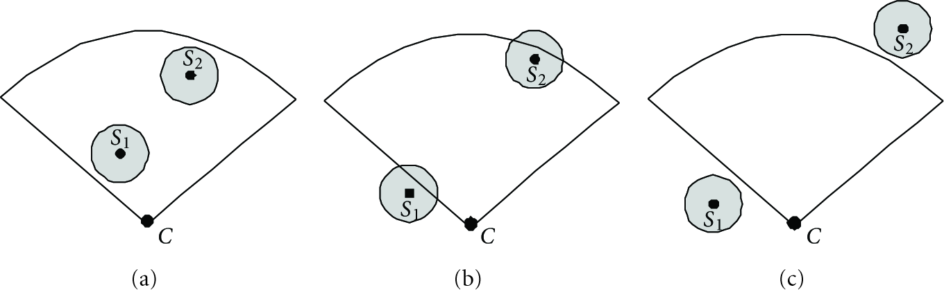
Sensing model relationships.
Definition 2 (sensing region).
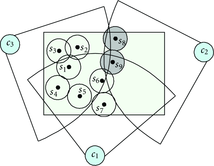
In the sensing field which is totally covered by the camera sensor nodes, the term sensing region refers to a set of points. Any two points belong to the same sensing region if they are covered by the same set of the camera sensor nodes.
For example, as shown in Figure 4, the rectangle sensing field which is totally covered by the camera sensor node

An illustrative example of sensing region.
Definition 3 (target region).
Target region refers to the sensing region in which the scalar sensors detect events. We define the set of target regions in the sensing field at one moment as
According to Definition 3, when a scalar sensor in a sensing region detects events, this sensing region will change to a target region. Then the set of the camera sensors which cover this target region will take part in the distributed coordination stage and some of them will be actuated to meet the requirement of event grade. However, when a scalar sensor in a target region detects events, except that higher event grade is required, the coordination among camera sensors is not needed because some camera sensors which cover this target region have been actuated already.
According to Definition 1, except the fringe, the scalar sensors in each sensing region are the inner nodes of the same set of camera sensors nearby. Therefore, the sensing field can be divided into sensing regions based on the classification of scalar sensors. The division process of the sensing field consists of three phases:
Phase 1: Detection of Neighbor Camera Sensors at Tier 2
Before calculating the sensing model relationships, all the scalar sensors in the network should know the sensing model information of camera sensors nearby. For the coordination among camera sensors, all the camera sensors in the network also should know the sensing model information of neighbor camera sensors. Therefore, each camera sensor in the network need broadcasts a CIM (camera information message) which includes its ID and the sensing model information before it goes to sleep state.
To ensure that all the neighbor camera sensors can receive the CIM while minimize the energy consumption of broadcasting, back-off mechanism is used. Each camera sensor defers for a random time before it broadcasts. The random time for the camera sensor node

where
From (1), we can see that the camera sensors broadcast the CIM in an order: starting with the camera sensor which has the largest sensing range, finishing with the camera sensor which has the smallest sensing range. Then the broadcasting range

By using this broadcasting range, all the neighbor camera sensors of
According to the CIMs received, each camera sensor creates an information list of neighbor camera sensors. Table 1 shows the data structure of one record in NeighborCList. This list will be used in the coordination stage of the camera sensors.
Data structure of one record in NeighborCList.

Phase 2: NewID Creation of the Scalar Sensors at Tier 1
In this phase, each scalar sensor estimates the sensing model relationships and the distances with the camera sensors nearby according to the CIMs received and records the results in MyCamera. In our scheme, we only need to consider two types of scalar sensors: inner nodes and fringe nodes. Here, the inner nodes refer to the scalar sensors which are totally covered by some camera sensors; the fringe nodes refer to the scalar sensors which are not totally covered by any camera sensor but still be partly covered by some camera sensors. The outer nodes which are not covered by any camera sensor will not take part in our scheme. Tables 2 and 3 show the data structures of MyCamera recorded in these two types of scalar sensors.
According to the information collected in MyCamera, each scalar sensor creates a NewID, as shown in Figure 5.
Data structure of MyCamera in inner node.

Data structure of MyCamera in fringe node.


NewID structure of the scalar sensors.
Phase 3: Classification of the Scalar Sensors at Tier 1
In this phase, each inner node at tier 1 broadcasts a NIM (Scalar sensor Information Message) which includes its NewID. Here we also use the back-off mechanism, and the broadcasting range of each node is determined by using the similar method proposed in the first phase. Then, each scalar sensor compares its NewID with the NewIDs in the NIMs received from the neighbor scalar sensors. If the sensor node finds that a neighbor scalar sensor has the same NewID content with it except ID, it will consider this neighbor scalar sensor as the same type, and add the ID of this neighbor scalar sensor in its NeighborSList (Neighbor Sensor node List).
For example, as shown in Figure 6,
Classification of the scalar sensor nodes.
It is easy to find that the scalar sensors which belong to the fringe nodes, such as

Distribution of the same type fringe nodes.
By the classification of the scalar sensors at tier 1 according to the coverage property of the camera sensors, the sensing field is divided into sensing regions before the running of the network. Then, during the running of the network, by forming a cluster of the scalar sensors in each sensing region, the events occurring in each sensing region can be managed by the scalar cluster head. Therefore, by hearing from the scalar cluster heads, each camera sensor can know the exact coverage overlaps without changing information with the neighboring camera sensors. Meanwhile, sensing-region management avoids repeatedly event reporting from scalar sensors.
4.2. A Voting Cluster Routing Algorithm
Clustering method in wireless sensor network has attracted great attention for its high efficiency. The main goal of cluster-based routing protocols is to efficiently maintain the energy consumption of the sensor nodes by involving them in multihop communication within a cluster and by performing data aggregation and fusion in order to decrease the number of transmitted messages to the sink.
Many clustering protocols have been proposed in the last few years [18–20]. In the case of clustering of the scalar sensors in each sensing region, to prolong the network lifetime, we want to select a cluster head based on the residual energy. Therefore, a voting cluster routing algorithm [21] is used. It consists of two phases.
Phase 1: Voting
At the beginning, each scalar sensor broadcasts a VM (Vote Message) which consists of its ID and residual energy. After receiving the VMs from other scalar sensors, each scalar sensor fulfills the process shown in Algorithm 1.
From the vote process shown in Algorithm 1, we can see that only the scalar sensors belonged to the same type can vote to each other. What is more, the distribution of the scalar sensors in the sensing region is also considered. Therefore, the nodes which have much residual energy and many nodes belonged to the same type around it will get many votes. These nodes will compete for being the cluster head in the next phase.
Myvote: number of the vote gotten from other scalar sensor nodes (1) While (receive VM) (2) If (VM-> ID ∈ NeighborSList) and (My ResidualEnergy > VM -> ResidualEnergy) (3) Myvote (4) End If (5) Drop (VM); (6) End While
Phase 2: Clustering
To support the event management by using clustering routing in each sensing region, all the inner nodes keep a MyCH. The data structure of MyCH is shown in Table 4.
In clustering phase, the scalar sensors whose vote is above a defined threshold broadcast a CFM (cluster forming message) to compete for being the cluster head. The data structure of CFM is shown in Figure 8.
The detail process for the cluster head election and routing forming is shown in Algorithm 2. We can see that minimum-hop principle is used to select the path to the cluster head. In this way all the inner nodes in a sensing region set up a cluster.
The operation of this voting cluster routing algorithm is controlled through rounds. To identify the sensing regions in the sensing field, we use the IDs of the cluster heads elected in the first round as the regionIDs. For all the fringe nodes, they treat themselves as sensing regions and regard their own IDs as the regionIDs.
Data structure of MyCH.

(1) If (Myvote >= JoinThreshold) (2) MyCH-> ClusterID = My ID; (3) MyCH-> Vote = Myvote; (4) MyCH-> ResidualEnergy = My ResidualEnergy; (5) MyCH-> HoptoCluster = 0; (6) MyCH-> ParentNodeID = My ID; (7) MyCH-> ParentNodeEnergy = My ResidualEnergy; (8) Write CFM using the information in MyCH; (9) Broadcast (CFM); (10) End If (11) While (receive a CFM from node s) (12) If (CFM->ID∈NeighborSList) / (13) If (MyCH->ClusterID ≠ CFM->ClusterID) / (14) If (MyCH->vote < CFM->Vote) or ((MyCH->vote = CFM->Vote) and (MyCH->ResidualEnergy < CFM->ResidualEnergy)) (15) Write MyCH using the information in CFM; / (16) CFM->HoptoCluster++; (17) CFM->ParentNodeID = My ID; (18) CFM->ParentNodeEnergy = My ResidualEnergy; (19) Broadcast (CFM); (20) Else (21) Drop (CFM); (22) End If (23) Else / (24) If (MyCH->HoptoCluster > CFM->HoptoCluster) or ((MyCH->HoptoCluster = CFM->HoptoCluster) and (MyCH->ParentNodeEnergy < CFM->ParentNodeEnergy)) (25) Write MyCH using the information in CFM; / (26) CFM->HoptoCluster++; (27) CFM->ParentNodeID = My ID; (28) CFM->ParentNodeEnergy = My ResidualEnergy; (29) Broadcast (CFM); (30) Else (31) Drop (CFM); (32) End If (33) End If (34) End If (35) End While

Data structure of CFM.
4.3. Event Management and Reporting
After the cluster forming process, the events occurring in each sensing region are managed by the cluster head in each round. Two messages are used by the scalar sensors during the running of the network.
(1) EM (Event Message)
EM is used by the members in the cluster to report the event information to the cluster head. The data structure of EM is shown in Table 7. EM consists of three parts: ID of the node who sends this message, EventType which shows the state of the event, and EventGrade which means the number of actuated camera sensors required for the event.
(2) WM (Wake Message)
WM is used by the cluster head in the sensing region or the fringe node to report the event information to the nearest camera sensor node. The data structure of WM is shown in Table 8. WM consists of four parts: NewID of the cluster head, RegionID of the sensing region, RegionType which shows the state of the sensing region, and highest EventGrade of the events in the sensing region.
The event management and reporting process shown in Figure 9 follows the steps below.
When a fringe node detects the beginning or ending of an event, it sends a WM to the nearest camera sensor. In this WM, the value of EventGrade is equal to the value of EdgeCameraNum in the fringe node's MyCamera to make sure that enough camera sensors can be actuated to cover the event.
When a member (inner node) in a cluster detects the beginning or ending of an event, it sends an EM to the cluster head. The cluster head in each region manages an EventList which records the reporting ID and EventGrade information of the events undergoing in this region. When receiving an EM, according to the value of EventType, the cluster head adds or deletes a record in the EventList or changes the value of EventGrade in a record. When the EventList is empty, this region is a sensing region, otherwise it is a target region. Thus, a WM will be sent out by the cluster head to the nearest camera sensor only under the following situations:
when a record is added in the empty EventList. It is means that once an event happens in a sensing region, the cluster head will send a WM when it receives the first EM to insure a quick response;
when the EventList becomes empty after deleting a record.
when the highest EventGrade in the EventList changes.

Event management and reporting process.
The EventList will be sent to the new cluster head in the next round. In this way, the events occurring in each sensing region are managed by the cluster head to insure a quick response while avoiding repeatedly event reporting which will result in the same coordination stage.
4.4. Distributed Camera Actuation
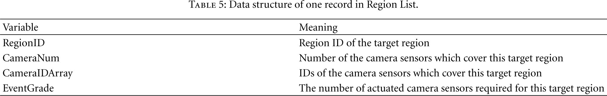
During the running of the network, besides a NeighborCList, all the camera sensors should keep a RegionList according to the WMs received. Table 5 shows the data structure of one record in RegionList.
Data structure of one record in Region List.
By using the information in NeighborCList and RegionList, the camera sensors can fulfill a distributed coordination to actuate the proper camera sensors according to the residual energy and event grade. The coordination among camera sensors after receiving a WM consists of two phases.
Phase 1: Broadcast of the WM among Camera Sensors
The camera sensor which receives the WM from tier 1 is the nearest camera sensor to the cluster head. It may not belong to the set of the camera sensors which cover the target region reported in the WM. Therefore, it broadcasts this WM within the transmission range decided by (2) to make sure that all the camera sensors which cover the target region receive this message.
Phase 2: Distributed Camera Actuation
All the camera sensors which receive the broadcasting WM from a camera sensor will activate their processor and run the distributed camera actuation algorithm shown in Algorithm 3. When a camera sensor goes to sleep state or actuated state, it will broadcast a SCM (state change message) which consists of its ID and state (00—sleep; 01—actuated). Residual energy of the camera sensor nodes is considered in this algorithm.
By using RegionList and NeighborCList, the coordination among camera sensors only needs a broadcast of WM and some short SCM announcements. Thus, the complexity and communication cost are greatly reduced.
ActuatedCameraNum: Number of the camera sensors that should be actuated SleepCameraNum: Number of the camera sensors that should be sleep (1) While (receive a WM) (2) update the content of TRNumArray in NeighborCList according to WM; (3) If (MyID∈WM->CameraIDArray) and (WM->RegionType = 01) and (MyState = 00) (4) ActuatedCameraNum = WM->EventGrade; / (5) For i =1 to WM->CameraNum / (6) If (NeighborCList(WM->CameraIDArray(i))->State = 01) (7) ActuatedCameraNum–; (8) End If (9) End For (10) If (ActuatedCameraNum > 0) / (11) Startup the timer; Initialize / (12) End If (13) While (Timer ≠ 0) (14) If (receive SCM->ID∈WM->CameraIDArray) and (receive SCM->State = 01) / (15) ActuatedCameraNum–; (16) End If (17) End While (18) If (ActuatedCameraNum > 0) / (19) SCM->ID = MyID; (20) SCM->State = 01; (21) Broadcast (SCM); (22) Actuate the camera; (23) End If (24) End If (25) If (TRNumArray of NeighborCList->MyID is empty) and (MyState = 01) / (26) SCM->ID = MyID; (27) SCM->State = 00; (28) Broadcast (SCM); (29) Close the camera; (30) End If (31) If (MyID∈WM->CameraIDArray) and (WM-> RegionType = 03) / (32) If (WM->RegionID->EventGrade in RegionList < WM->EventGrade) and (MyState = 00) / (33) Go to 4; (34) End If (35) If (RegionList(WM->RegionID)->EventGrade > WM->EventGrade) and (MyState = 01) / (36) If (RegionList only has one record of WM->RegionID) / (37) SleepCameraNum = RegionList(RegionID)->EventGrade-WM->EventGrade; (38) Startup the timer; Initialize (39) While (Timer ≠ 0) (40) If (receive SCM->ID∈WM->CameraIDArray) and (receive SCM->State = 00) (41) SleepCameraNum–; (42) End If (43) End While (44) If (SleepCameraNum > 0) (45) Go to 26; (46) End If (47) End If (48) End If (49) End If (50) Update RegionList according to WM; (51) Update NeighborCList->State according to SCM; (52) End While
5. Simulations
5.1. Simulation Setup
In this section, we have conducted ns-2 [22] simulations for the performance evaluation. The default parameters are set in Table 6. 500 experiments under different topologies are repeated and an average of the results is taken.
Simulation parameters.

Data structure of EM.

Data structure of WM.

We considered the following performance metrics.
Energy consumption: the communication energy consumption model presented in [23] and the processor energy consumption models presented in [24] are used.
Response latency: defined as the time from the moment of detecting an event by a scalar sensor to the moment of capturing the first event image by a camera sensor.
Coverage ratio: defined as the portion of the area of an event which is covered by all actuated camera sensors with respect to its total area.
FoV utilization: defined as the ratio of the area of an event covered by all actuated camera sensors to the total area of FoVs of all actuated camera sensors. The higher this ratio is, more redundancy can be eliminated.
5.2. Performance Evaluations
In this section, we assess the performance of DCCA-SM under a variety of conditions. We also compare it with DCA-SC [13]. In the experiments, the transmission range of scalar sensors in DCA-SC is 10 m to make sure that each camera sensor can record the IDs of all scalar sensors within its FoV, and the transmission range of camera sensors in DCA-SC is 20 m to ensure the communication with neighboring camera sensors.
5.2.1. Energy Consumption
The two-tier event-driven camera actuation strategy is proposed to lighten the energy consumption burden on camera sensors so as to prolong the network lifetime. Therefore, we compared the energy consumption per node in DCCA-SM and DCA-SC for initialization, event reporting, and coordination as the metrics to evaluate the performance.
Energy Consumption for Initialization
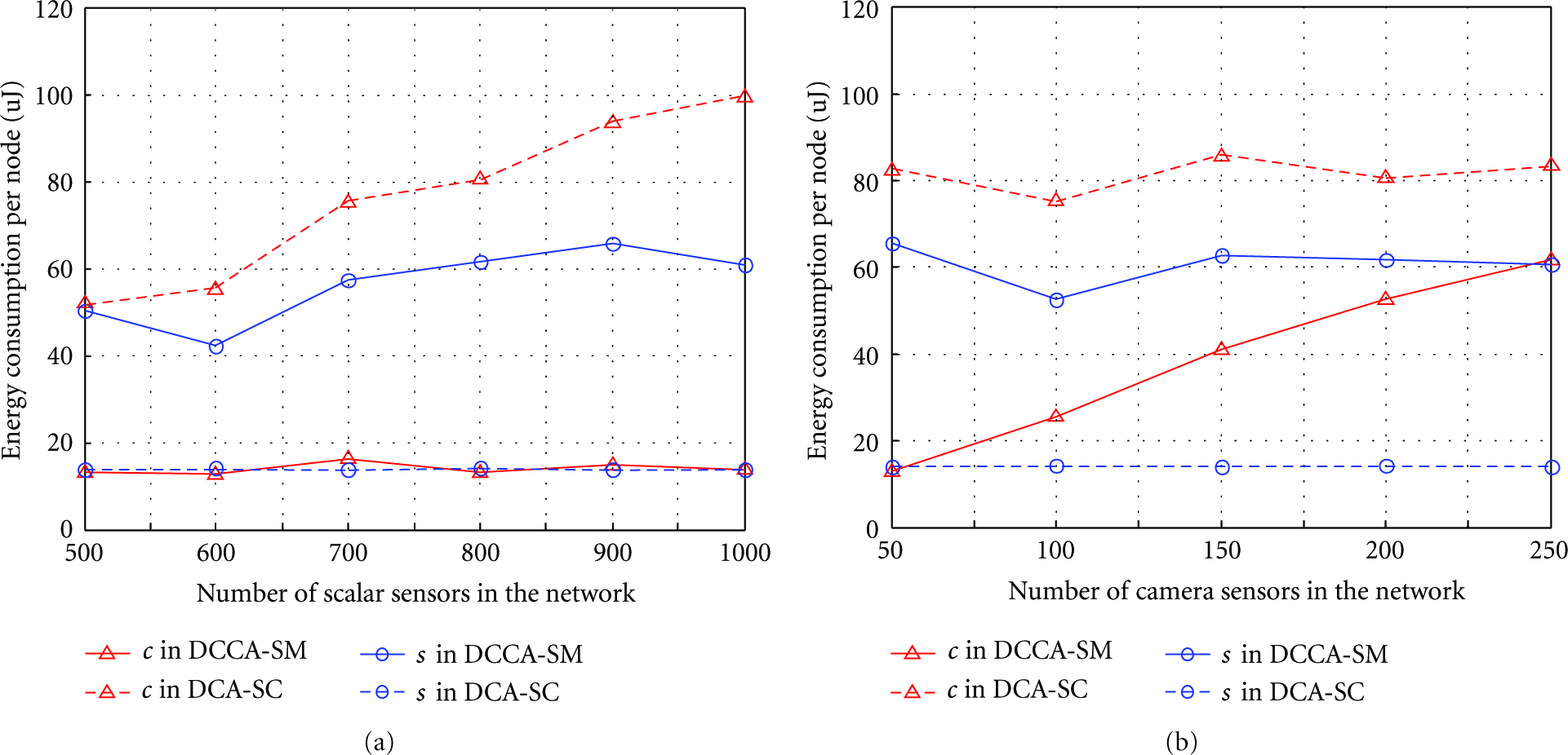
Firstly, we let the number of camera sensors be 150 and conducted experiments with varying number of scalar sensors. The algorithm presented in our previous work [25] to calculate the coverage relationship between camera sensors and scalar sensors is used. Figure 10(a) shows the energy consumption per node for initialization. It is apparent that the energy consumption of each camera sensor in DCA-SC is much higher than that in DCCA-SM and increases greatly as the number of scalar sensors increases. This is because the coverage relationship table is maintained at each camera sensor in DCA-SC. As the number of scalar sensors increases, each camera sensor consumes more energy in receiving the messages from the scalar sensors and calculating the coverage relationships for initialization. However, for DCCA-SM, the coverage relationship table is maintained at each scalar sensor. For each camera sensor in DCCA-SM, it only needs to broadcast its position, view angle and ID. What is more, although each scalar sensor in DCCA-SM also needs to receive the messages from the camera sensors and calculating the coverage relationships for initialization, the energy consumption of each scalar sensor in DCCA-SM is much lower than that of each camera sensor in DCA-SC because the density of camera sensors is much lower than that of scalar sensors in the network.
We further let the number of scalar sensors be 600 and conducted experiments with varying number of camera sensors. Figure 10(b) shows the energy consumption per node for initialization. It can be observed that the energy consumption of each sensor in DCCA-SM increases as the number of camera sensors increases, but it is still much lower than the energy consumption of each camera sensor in DCA-SC.

Energy consumption per node for initialization under varying number of sensors.
Energy Consumption for Event Reporting
In this experiment, we assume that the event area is 25 πm2. Firstly, we let the number of camera sensors be 150 and conducted experiments with varying number of scalar sensors. Figure 11(a) shows that DCCA-SM greatly lightens the energy consumption burden on the camera sensors for event reporting compared with DCA-SC. We further let the number of scalar sensors be 600 and conducted experiments with varying number of camera sensors. Figure 11(b) shows that the energy consumption of each camera sensor in DCCA-SM increases as the number of camera sensors increases, because more camera sensors lead to more overlaps and sensing regions, but it is still much lower than the energy consumption of each camera sensor in DCA-SC.
Energy consumption per node for event reporting under varying number of sensors.
We also compared the energy consumption per node in DCCA-SM and DCA-SC for event reporting under different event areas. In this experiment, we let the number of camera sensors be 150 and the number of scalar sensors be 600. We can see in Figure 12 that the energy consumption of each camera sensor in DCA-SC increases greatly as the radius of event area increases. This is because the number of scalar sensors detected the event increases as the radius of event area increases. Then the camera sensors will receive more messages from tier 1. However, for DCCA-SM, although the number of target regions also increases as the radius of event area increases, the rising rate is much lower. Besides, the camera sensors in DCCA-SM do not need to receive all the messages from the target regions. Therefore, the influence of event area size on the energy consumption of each camera sensor in DCCA-SM is small.

Energy consumption per node for event reporting under different event areas.
Energy Consumption for Coordination
In this experiment, we let the number of scalar sensors be 600 and varied the number of camera sensors. The parameter α in DCA-SC is set to 0. Figure 13 shows the energy consumption per camera sensor in DCCA-SM and DCA-SC for coordination. We can see that the energy consumption per camera sensor in DCA-SC is much higher than that in DCCA-SM and increases rapidly as the number of camera sensors increases. The reason is that the camera sensors in DCA-SC need to exchange the information with the neighbors to determine the possible coverage overlaps, while the camera sensors in DCCA-SM know the coverage overlaps from the scalar sensors.
From the experiments and results above, we can see that DCCA-SM can efficiently lighten the energy consumption burden on camera sensors, compared with DCA-SC.

Energy consumption per node for coordination under varying number of camera sensors.
5.2.2. Response Latency
In this set of experiments, we varied the number of scalar sensors and the size of event area to see their influence on the response latency in DCCA-SM and DCA-SC. Firstly we assume that the event area is 25 πm2 and let the number of camera sensors be 150. Figure 14 shows the result. The response latency in DCA-SC increases as the number of scalar sensors increases. Since there is no need for the camera sensors in DCCA-SM to receive all the messages from the scalar sensor detected the event within the FoV before collaborative actuation, the response latency in DCCA-SM is much lower than that in DCA-SC. Due to the same reason, we also can see this result by changing the size of event area, as shown in Figure 15.
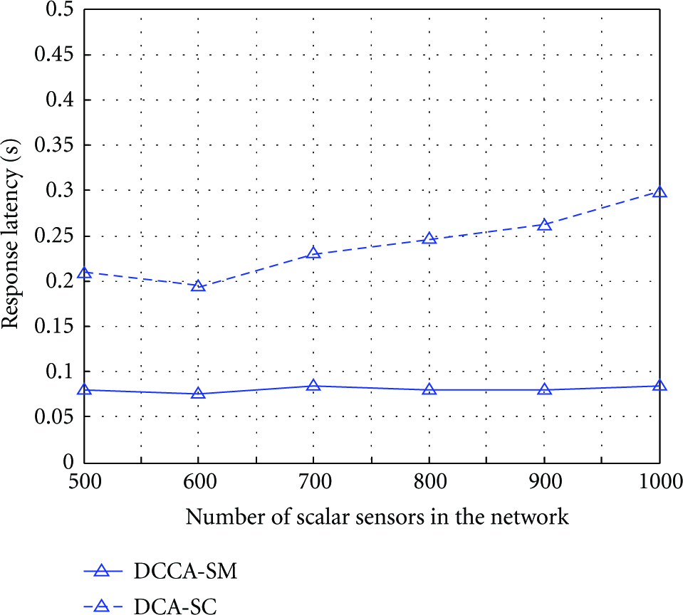
Response latency under varying number of scalar sensors.

Response latency under varying radius of event area.
5.2.3. Coverage Ratio
In DCCA-SM, once an event occurs, all sensing regions which detect the event will turn into target regions and cause the coordination among camera sensors. It means that the coverage ratio is always maximized in DCCA-SM. It is equivalent to the situation when the parameter α is set to 0 in DCA-SC. Therefore, no comparison is provided in this section.
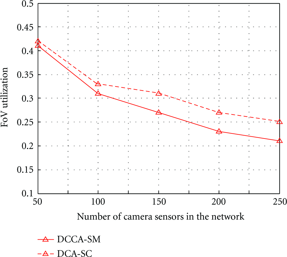
5.2.4. FoV Utilization
We tested the FoV utilization performance of DCA-SC with respect to DCCA-SM under varying number of camera sensors. In this experiment, the parameter α in DCA-SC is set to 0. The results in Figure 16 reveals that DCCA-SM performs slightly worse than DCA-SC due to the priority mechanism based on the residual energy instead of the event coverage, which will result in higher transmission costs.
FoV utilization performance under varying number of camera sensors.
6. Conclusions
Considering the high energy consumption of image acquisition, computation and transmission in wireless multimedia sensor networks (WMSNs), two-tier network structure is usually used to lighten the energy consumption burden on camera sensors. Thus, a camera sensor can only be actuated when an event is detected by scalar sensors within its field-of-view (FoV). In this paper, the event-driven camera actuation problem is brought forward and studied. By treating this problem as the coordination problem in WSANs, we propose a distributed collaborative camera actuation scheme based on sensing-region management (DCCA-SM).
The scheme consists of three stages: initialization, event detecting and reporting, and coordination among camera sensors. In the initialization stage, we let all the scalar sensors at tier 1 calculate the sensing model relationships with the camera sensors nearby. Thus, the camera sensors can be easy to know whether they cover the events or not without any event coverage estimation algorithm during the coordination stage. During the event detecting and reporting stage, the sensing field is divided into sensing regions based on the classification of scalar sensors and the events occurring in each sensing region are managed by the cluster head which is periodically selected according to residual-energy among the scalar sensors. In this way, we can provide a quick response while avoiding repeatedly event reporting. The comparative performance evaluations on energy consumption and response latency demonstrate effectiveness and energy efficiency of the proposed scheme. For DCCA-SM cannot minimize the set of actuated camera sensors which provide maximized coverage for the events, we will further study the minimum set cover problem in WMSNs in our future work.
Footnotes
Acknowledgments
This work was supported by the National Science Foundation of PR China under Grant nos. 60872151, 61003302 and 61171136. We are grateful to all the reviewers for their insightful comments which improved the quality of the paper.