
Abstract
The Ti-6Al-4V octahedral porous material unit is designed to calculate its load. In this paper, ANSYS is adopted for the load simulation of the unit. And a simplified model of dimensional theoretical calculation is established, by which the analytical equation of the fracture load is obtained and the calculation of the load of Ti-6Al-4V is completed. Moreover, selective laser melting is adopted in processing the Ti-6Al-4V porous material unit. The experimental value of fracture load of this material is obtained through compression experiment. The results show that the simulation curves approximate the variation tendency of the elastic deformation of the compression curves; the curves of theoretical calculation approximate the general variation tendency; and the experimental value of fracture load is very close to the theoretical value. Therefore, the theoretical prediction accuracy of fracture load is high, which lays the foundation for the mechanical properties of the octahedral porous material.
1. Introduction
In most cases, the mismatch of mechanical properties between implants and bone caused by the stress shielding is one of the important reasons for the failure of clinical implants [1]. The mechanical properties of bone depend on many factors such as anatomical position, age, and gender [2]. Nowadays, the standard for judging whether the implants match the bone is the Young modulus, which however cannot be obtained without the load and the deformation displacement of the material.
Compared with the implants processed by other materials, the Young modulus of compact Ti-6Al-4V implant is most close to the cortical bone while outclasses the cortical bone. In order to reduce the discrepancy on Young modulus, most researchers process Ti-6Al-4V into porous material.
The conventional porous material processing techniques are mainly as follows: space holder technique [3], freeze casting [4], rapid prototyping [5], or laser processing [6], among which the space holder technique and freeze casting are mainly applied to processing the randomly distributed pores; while the rapid prototyping and laser processing are applied to control the distribution position, morphology, and size of the pores. With the space holder technique, we can get the porous structure with higher porosity; however, there is a big difference between the mechanical properties of the structure and the bone [3]. Meanwhile, the Young modulus of porous structure processed by the freeze casting technique is the closest to bone tissue. Nevertheless, the freeze casting technique can only be used to process the pores smaller than 300 μm and the processing cycle of it is relatively long with usually more than 7 days [4]. Therefore, in view of all the disadvantages mentioned above, the porous material processed by the space holder technique and the freeze casting technique are unable to meet the demands of the implant. And recent researches have shown that the rapid prototyping and the laser processing techniques can be used for processing the porous material with simple shapes and have already been applied in the processing of titanium alloy porous material.
The selective laser melting (SLM) technique adopted by this paper is a kind of laser processing technique, an emerging parts’ manufacturing technique since the 20th century which uses laser to melt the metal powder so as to realize the metallurgic bonding of the metal powder without traditional cutting, and theoretically it can form the metal part into any shape with the density higher than 95%. The parts manufactured through SLM have the characteristics of high density, good mechanical properties, high dimension accuracy (error of part dimension is less than 0.1 mm), direct and practical usability without or with simple postprocessing. Thus SLM is better than the traditional techniques in part design, making time, and so forth and has been widely applied in industries of aerospace, medical treatment, automobiles, dies, and so forth [7–11].
The researches on porous material in the world are mainly concentrated in the following aspects. Oh et al. [12] have found the corresponding relation between the porosity of titanium alloy porous structure and the Young modulus; Heinl et al. [13] have found through researches that holes in the implants promote the growth of osteocyte; researches done by Otsuki et al. [14] show that only when the pores are interlinked they can have a promoting effect on the growth of osteocyte; Xue et al. [15] have found that when the size of the implant pore is smaller than 100 μm, the osteocytes are unable to grow; Chen et al. [16] have experimented the effect of the pore size on the 100 μm–400 μm osteogenesis on structures on the growth of the osteocyte; Hollander et al. [17] have experimented that the porous materials with pore sizes of 500, 700, and 1000 μm and have found that such pore sizes have a preferable promoting effect on the growth of human osteocyte.
The analyses above show that the research works done by most scholars are focused on the effect of the pore size on the growth of the osteocyte in the implants, while the researches on the mechanical properties of the obtained porous materials are relatively less. However, with the increase of the clinical applications with the porous materials, the mechanical property of them has become a nonnegligible aspect for the research. Moreover, the porous material unit is the basis for the research of porous material. This paper has first designed the octahedral porous material unit; then uses ANSYS to simulate the load of the unit; has built the simplified dimensional theoretical model to calculate the theoretical load of the Ti-6Al-4V porous material unit; moreover, the paper has adopted the SLM to process the octahedral porous material unit, then got the experimental load and the deformation displacement through compression experimental, and finally, has got the relationship among the simulation value, the theoretical calculation value, and the experimental value by comparison, which provides the basic data for researches in the future.
2. Experimental Material and Methods
2.1. Experimental Equipments
The experiment uses the DiMetal-280 SLM rapid prototyping equipment developed by the South China University of Technology. The main structure of DiMetal-280 is as Figure 1 shows. And its main parameters are as follows: laser with wavelength is 1075 nm, SPI 200 W cw fiber laser; the maximum dimension manufactured is 280 × 280 × 300 mm (L × W × H); laser scanning mode: X-Y galvanometer scanning and focused by f-θ lens with scanning speed is in a range of 5–5000 mm/s; beam quality factor is
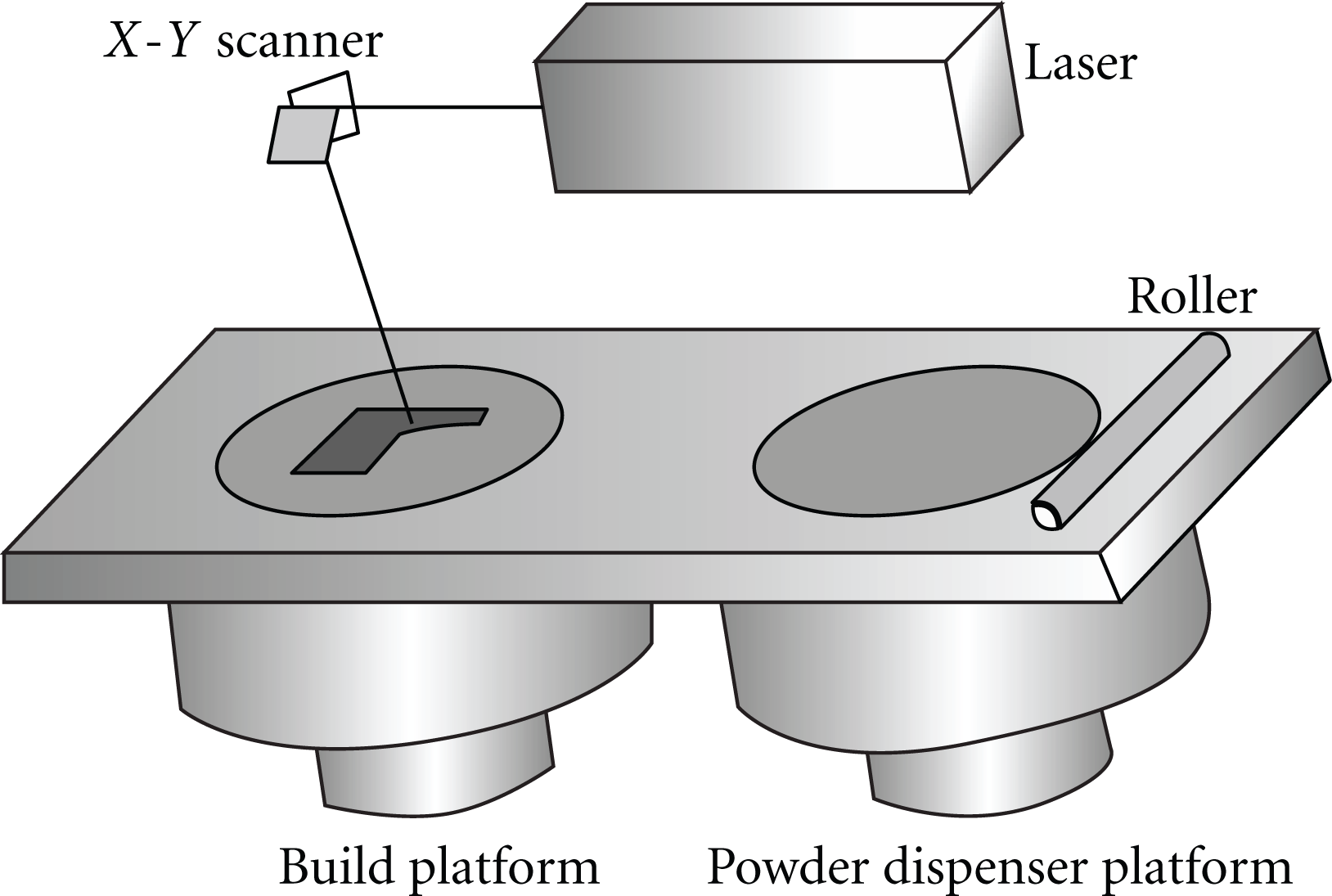
Schematic diagram of SLM.
2.2. The Experimental Material and Methods
The experiment uses gas atomized Ti-6Al-4V powder, and its composition is listed in Table 1 (wt.%). And it is ensured that the diameters of 90% powder grains are less than 20 μm.
Powder composition of Ti-6Al-4V.

The experiment uses the 100 mm × 100 mm × 20 mm Ti-6Al-4V substrate for processing. The parameters after optimizing are as follows: power is 80 W, scanning speed is 200 mm/s, powder thickness is 0.02 mm, scanning strategy is X-Y inter-layer stagger, and the hatch spacing is 0.06 mm. The density reaches 95%. Argon serves as the shielding gas to ensure that the oxygen content is under 0.2%. Successively sanding of the cross-section with 200#, 400#, and 800# sand papers followed by the ultrasonic cleaning of it in acetone solution for 20 minutes, and after its drying is corrosion in nitrate acid and hydrofluoric acid solution for the observation of the cross-section's microstructure. With the hypothesis that in the theoretical calculation the section of the strut is round and has homogeneous distribution of the stress and the composition, then the neutral axis would coincide with the moment of inertia. The maximum stress is generated in the straight line which crosses the circle center horizontally on the section. The density of strut is 95%. If we let the well-distributed pores have effect on the cross-section area of the strut, then we obtain the compressed area of the unit:
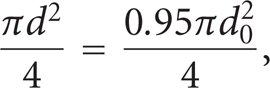
where
3. Experimental Results and Discussion
3.1. ANSYS Simulation Analysis
3.1.1. ANSYS Theoretical Analysis
The displacement method is one of the basic methods for calculating the statically determinate structure and the statically indeterminate structure. For the high-degree indeterminate structure, as there are many redundant unknown forces, the calculation would be complicate in the analysis of its internal force with the force method. However, the displacement method is a calculation method which uses the nodes as unknown quantities and utilizes the correlations of deformation and the internal force; the number of nodes (the number of the unknown quantities) is irrelevant to the degree of the indeterminacy. Along with the widespread use of computers, a new method for structural analysis has been developed—the matrix displacement method. This method, on the basis of the displacement method, has cancelled the hypothesis of ignoring the axial deformation and the shear deformation while calculating the displacement of the strut, and in order to normalize all calculations and to avail the program composition, the method has matrixed all the computational equations, that is, to expound the displacement method with the matrix; thus, it is also known as finite-element method of skeletal structures. The basic thought of solving problems through the matrix displacement method is “break up the whole into parts and combine parts into whole.” First, we disperse the original structure into units of finite number, and then on the consideration of the balance and continuous conditions of the nodes, we combine the dispersed units into their original structure. Through doing this, the complex structural calculation problems would be turned into simple problems about unit analysis and combination. As the matrix displacement method is simple and easy and has a higher calculation accuracy and speed, it can be applied in analyzing the steel frame, truss, continuous beam, continuous arch, and the continuous frame and thus occupies an important position in the calculation of engineering structure. Using the regular method for analyzing the load of the porous structure, the paper simplifies the unit of the octahedral porous material into the space truss structure [18].
(1) The Stiffness Matrix of the Space Structure Unit


From (2), (3), and (4), the equation under the condition of coordinate transformation is derived:

where E is the Young modulus of the strut; G is the shear modulus of the strut; A is the section area; I Y ,I Z are the moments of inertia of the section; J is the polar moment of inertia of the section; l is the length of the strut.
(2) Coordinate Transformation Matrix
The process, in which the unit stiffness matrix under the local coordinate system would be transformed into the whole unit coordinate system, is realized through the transformation of the coordinate. Let the coordinate transforming matrix be T, then

Equation (7) is derived from(2) and (6):

Equation (8) is derived from (7):

Equation (9) is derived from(8):

Since

Let

The matrix T is
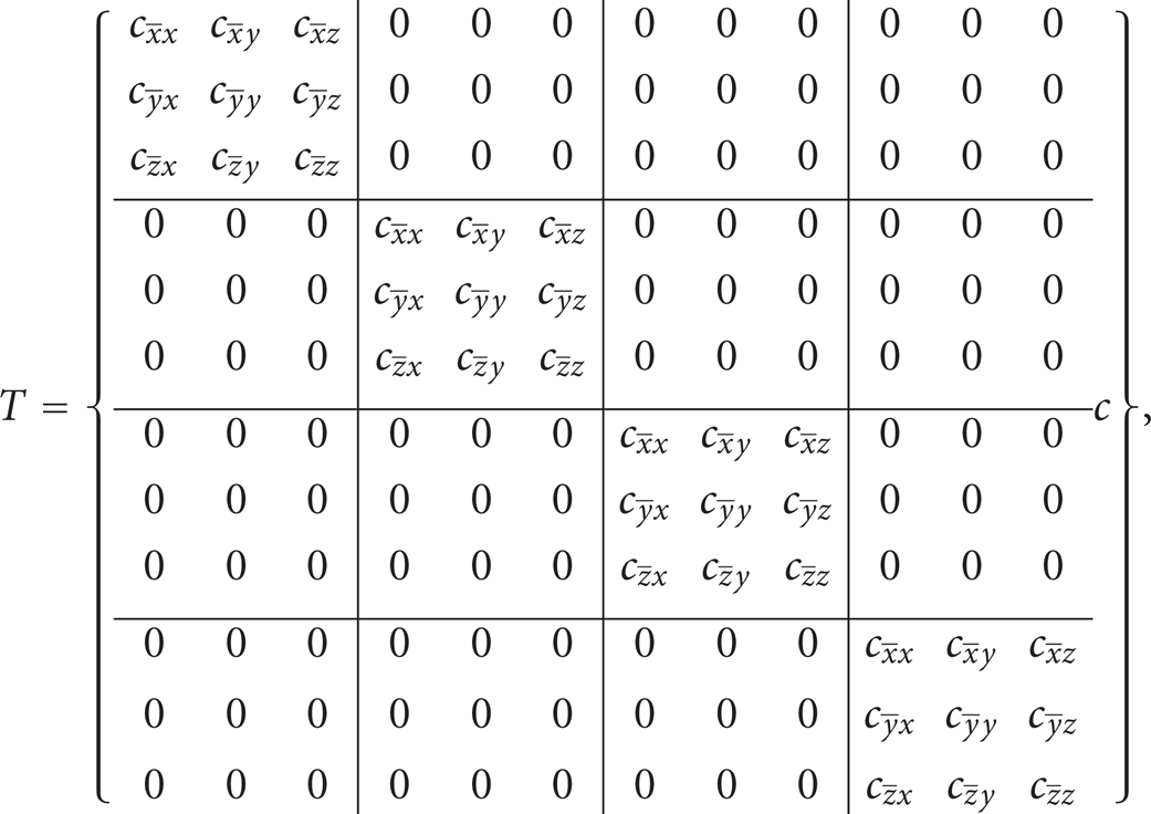
where
3.1.2. The ANSYS Simulation Based on the Displacement Method of the Space Truss Matrix
Figure 2 is the schematic diagram of the octahedral unit. Figure 3 is the finite-element model of the octahedral unit. Modeling of the octahedral unit in ANSYS software, the nodes of it are solid nodes while the space warp and rotation are not taken into consideration. And dichotomy is applied in the cyclic loading of the force. And when allowable stress of the holding strut reaches

Schematic diagram of the octahedral unit (

Finite-element model of the octahedral unit.
3.2. The Establishment of the Theoretical Simplified Model
3.2.1. The Calculation of the Theoretical Load
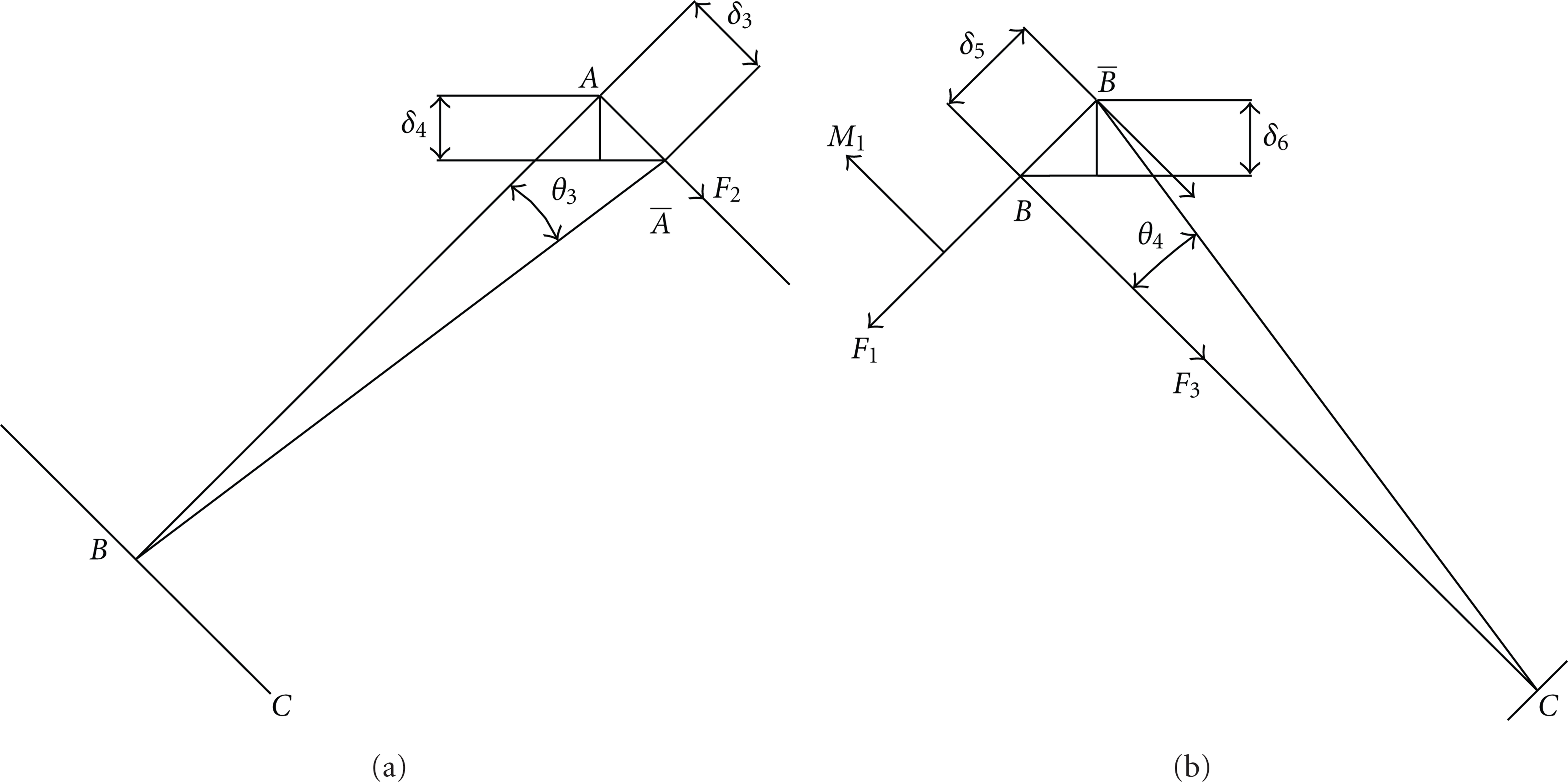
First conduct calculation for struts AB and AD: for strut AB, decompose force F into F
A,B
along strut AB and


Schematic diagram of the force on the unit: (a) schematic diagram of the force on strut AB and (b) schematic diagram of the force on strut BC.
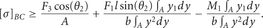
The pressure stress and the bending stress satisfy
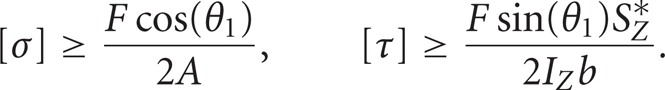
The maximum allowable stress follows from(13) and (14) that
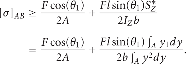
And with the assumed conditions, it is derived that

From (15) and (16), it is obtained that

When
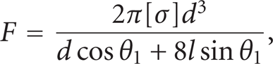
where
3.2.2. Calculation of the Theoretical Displacement
Because of the characteristics of the SLM, it can be considered that the node of the top chord and the bottom chord is multiconstrained for the two struts. Thus, the top chord and the bottom chord can be simplified as one end is fixed while the other end is free.
It follows from Figure 5 and the flexural equation that

where M is moment and I is moment of inertia.
Schematic diagram of flexural deformation: (a) schematic diagram of strut AB and (b) schematic diagram of strut BC.
It follows from (19) that

It follows from Figure 5 that

And from the Hooke's law, the compression deformation produced by force F1 on strut AB is obtained:

So the total deformation of strut AB is obtained:
For strut BC, its force condition shown in Figure 4(b), in which M, the bending moment produced by F1, equals to
Equation (24) deforms to

Equations (15) and (25) indicate that the dangerous point is point B.
And it follows from the flexural equation that

And thus it is obtained that

According to the Hooke's law, the compression deformation produced by force F3 on strut BC is

The total deformation of strut BC follows from (28) and (29):

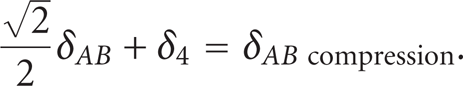
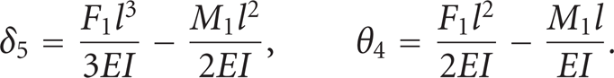
The total deformation displacement of the unit follows from (23) and (30):

Through the calculation above, it is deduced that the load of the octahedral unit and the displacement satisfy the following relationship:

Let

3.3. The Experimental Load
The regular octahedral units in the experiment are designed according to the data in Table 2; the morphology of the units is shown in Figure 6.
Design of octahedral data.


Octahedral unit ((a) is sample 1, (b) is sample 2, (c) is sample 3, and (d) is sample 4).
Figure 6 shows the processed octahedral unit, while Figure 7 shows the octahedral unit of sample 2 after its compression; during the process of the compression the most dangerous point appears on point B, which agrees with the result deduced from the theoretical calculation.

Sample 2 after compression.
Figure 8 shows the compression curves. The data in Table 3, obtained through Figure 8, formulas (18) and (33), demonstrates that the relative error between theoretical and experimental maximum load and the relative error between theoretical and experimental compression displacement are small, which in turn indicates that the predication accuracy of the model is relatively high.
Compression data of the experiment.

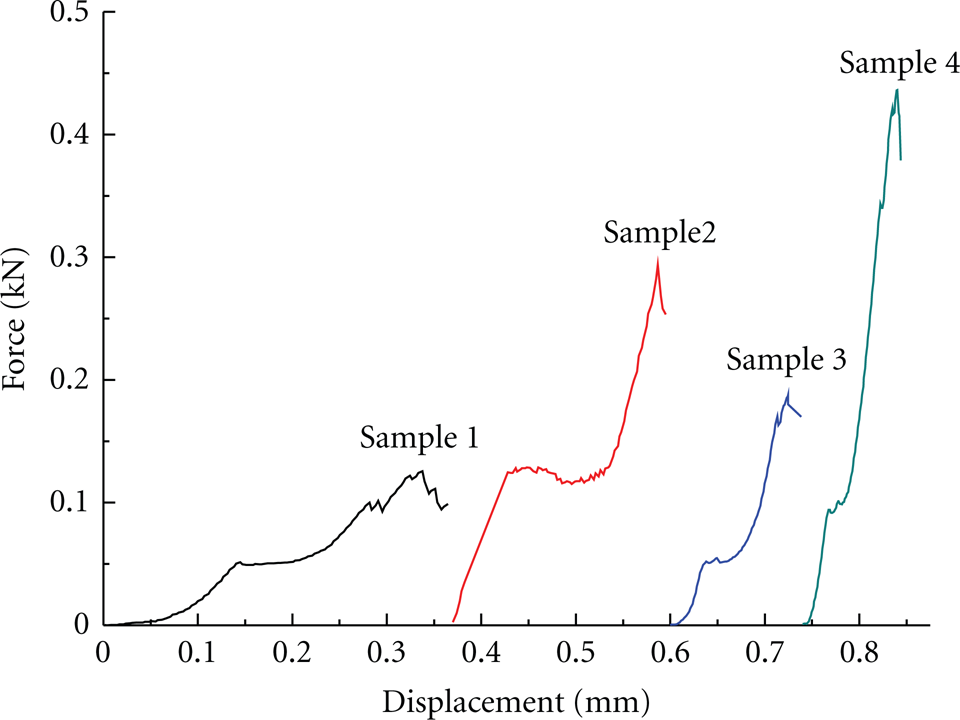
Experimental compression curves of the octahedral units.
3.4. The Simulation Value and the Experimental Value of ANSYS
By the comparison of the ANSYS simulation value and its experimental value, it is discovered that the simulation curve better reflect the elastic deformation trend in the compression curve. However, there is a considerable difference between the maximum deformation displacement and the maximum load in the simulation value and the experimental value. The reason is that after the processing by the selective laser melting, the node is approximate to the welded node; moreover, in the simulation the top chord and the bottom chord, with a fixed end, default to multiconstrained. In addition, neither the bending between the two struts (which means that strut AB rotates with strut BC around point B along direction Y as shown in Figure 4) nor the effect of a strut's bending on the load is considered; nevertheless, in the process of compression the bending between the two struts is the main factor to affect the load. The dangerous point of the unit in the simulation process is point C or any other point on the strut instead of point B. And the main fracture source in the simulation is the axial force of the strut, so as a result the strut in the process can be simplified as in Figure 10: one end is fixed while the other end is free. By this way, the bending of strut can be turned into stability problem of the compression bar. But in processing, this situation would only occur when “the length of the strut/the cross-section area” satisfies a certain relation.
It follows from Euler formula that

where λ p is the compliance and σ P is the proportional limiting stress.
With regard to the materials adopted by the paper, it follows from (34) that

It follows from Euler empirical equation that

where μ is the length factor; i is the radius of inertia
It is obtained from (36) that

Thus
The analysis above shows that the dangerous point in the simulation process could only be point C. This is because strut AB and strut BC are deemed as a whole, and while under stress the most dangerous point would be the contact point below. However, in experiment the dangerous point occurs on point B instead. Just as the morphology of the unit after the compression shows in Figure 7, the top chord is fractured while the bottom chord remains relatively unchanged. And this is all because during the compression, there is a relative rotating between the top chord and the bottom chord, and thus the force at point B—the focal point of stress–is the highest, and the failure appears first at point B too. Figure 9 shows that in the compression process, the variation tendency of the elastic deformation approximates the variation tendency of the simulation curve, which illustrates that the deformation displacement at the initial stage of the compression is mainly produced by the elastic deformation of the top chord and the bottom chord under the axial pressure. For example, as shown in Figure 9 of sample 2, OA stands for the stage of elastic deformation, while other parts are the stage of plastic deformation. In the beginning of the compression, the sample enters the stage of elastic deformation and then enters the stage of plastic deformation arriving at point A. BC is the yield stage and CD is the stress-hardening stage. The reason why the sample did not show the linear relationship in its elastic deformation stage is because the actual sample is a structural part. There is relative rotation in the process of compression and its displacement direction is vertical component of the strut compression direction. Thus, the compression displacement and the load are in accord with the trigonometric function. As a result, the elastic deformation stage is not a straight line.

Simulation curves and experimental compression curves of sample 2.

Schematic diagram of compression of the strut.
3.5. The Theoretical Calculation and the Experimental Value
It can be found via Table 3 that the theoretical load and deformation displacement are smaller than the actual values. And the reasons for that are as follows.
3.5.1. The Section Simplification Error
(1) The Section Simplification Error of the Upper-End Section and the Lower-End Section
In theoretical calculation of the model, the top of it would be simplified to a section area of one strut, while in fact the morphology of the processed model top, as it is shown in Figure 2, is the overlapped section of the strut. The experimental section area is larger than the section area obtained through the theoretical calculation, while under the circumstances that the allowable stress is unchanged; the increasing of the section area contributes to the improvement of the load.
(2) The Simplification Error of the Nodes
In theoretical calculation, the node is defaulted to hinge node without consideration of the junction point’ section area. Strut AB and strut BC rotate around each other without any resistance along direction Y (Figure 4). However, the real parts’ connection is approximate to semirotary and semisolid node. Strut AB can rotate with strut BC around point B along direction Y, which at the same time is not the rotation entirely without any resistance, and when the angle is larger than certain value the struts would fracture. When the compression begins, strut AB and strut BC start elastic deforming first, then strut AB would have microrotation around strut BC. With the increase of the load, the rotation would reach its limit, and at this time the continuous increase of the load would lead to the plastic deformation of the octahedral unit. By comparison with the theoretical calculation, as node B has the section area, the experimental load is somewhat increased.
It is derived from (33) and the compression curves as in Figure 9 that within the range of the allowable stress, the deformation displacement is directly proportional to the load, which means that the increase of the load would result in the increase of the deformation displacement. As a result of this, the experimental load and deformation displacement are greater than the theoretical ones. Substitute the experimental load into (18); let the experimental load is 125.61 N, then the theoretical deformation displacement is 0.2938 mm–0.0200 mm away from the experimental displacement; relative error is 6.8%.
(3) The Data Processing Error
In theoretical calculation, the section of the material is round, but in processing it cannot be completely round as required by theory. This is because in the slicing procedure, the triangle facet is applied in the approximation of the actual size and shape, while the straight line is applied for the approximation when processing an arch. Therefore, the parts’ section after the processing can only be considered as approximate circular rather than a real circular. Meanwhile, some adhesions in the SLM processing also contribute to the increase of the section dimension, which improves the load. Figure 9 indicates that the theoretical curves can better reflect the variation tendency of the experimental compression curves.
3.6. Analysis of the Fracture Morphology
The fracture morphology, as Figure 11 shows, is flat and uniform. The river and shell patterns in the figure have the typical characteristic of physical fracture. In microscopic view, Ti-6Al-4V belongs to brittle fracture. However, in microscopic view, it is able to find the existence of some dimples and tearing ridges, while the dimples, with the irregular shape and small number, have an uneven distribution. Thus as a result, the fracture mode of the Ti-6Al-4V alloy is a mixed fracture mode based mainly on the brittle fracture. In structural transformation, large amounts of Al supersaturated solid solution are produced in Ti-6Al-4V because of the rapid condensation. And when the concentration increases to exceed the concentration of the supersaturated solid solution, the aluminide: Ti3Al. Ti3Al precipitated in the crystal boundary is the typical brittle microstructure, which is prone to crack and then render the cracks to expand rapidly under pressure, and so there are obvious traces of brittle fracture on the fracture morphology.

Morphology of fracture: (a) river and shell patterns; (b) dimple.
Because of the characteristics of the short-time laser heating and fast temperature rising, the parts obtained have relatively small grains. According to the analysis of the fracture morphology, it can be considered that the fracture process is as follows: after cracks are produced on the material, the crystal boundary of the material is aggregated with a lot of dislocations under the influence of the external stress. And the continuous increase of the external stress leads to mass multiplication of the dislocations which results in the increase of the energy of the crystal boundary and then a poor stability of it, and then the stress concentration is gradually produced. Along with the proceeding of the experiment, the cracks expand along the martensite phase grain section until its failure at last.
4. Conclusion
This paper designs a kind of octahedral unit. First, the paper adopts ANSYS to simulate its load; then calculates its theoretical load through building a dimensional simplified model; adopts SLM to process the unit and obtains its experimental load from compression experiment. The conclusions obtained are as follows.
ANSYS simulation curves are in good agreement with the variation tendency of the elastic deformation in the compression curves.
The theoretically calculated load of the octahedral unit satisfies the equation:
The analysis of the fracture morphology indicates that the fracture of the octahedral unit is the brittle fracture which belongs to cleavability fracture.
Footnotes
Acknowledgments
The authors gratefully appreciate the financial support from the Industry, University and Research Institute Combination of Ministry of Education, Ministry of Science and Technology and Guangdong Province, China (Project no. 2010A090200072).