
Abstract
The basic sensing behaviors of Pulse-Prepump Brillouin Optical Time Domain Analysis- (PPP-BOTDA-) based distributed fiber optic sensors (DFOSs) with a spatial resolution on the order of 0.1 m are first experimentally studied. Second, the sensing results for different types of optical fibres are compared. Based on these investigations, the performance of PPP-BOTDA—based DFOSs for crack monitoring is evaluated. The experimental results show that in the interior of an optical fibre, slippage between the bare fiber and the coating materials occurs and that different types of optical fibres have different degrees of slippage. Point fixation bonding methods can produce effective and correct measurement results when the gauge length of the optical fibre is longer than the critical effective sensing length (CESL), whereas the overall bonding method is still not feasible for monitoring localized deformation quantitatively. Finally, the differences between Brillouin Optical Time Domain Reflectometry (BOTDR) and BOTDA are discussed.
1. Introduction
As a novel and advanced sensing technique, fiber optic sensors (FOSs) have been extensively researched for structural health monitoring (SHM) purpose due to their distributed sensing, rapid data transmission, small dimension, ease of installation, and immunity from electromagnetic influence. Among them, the Brillouin-based sensing is a one type of the most useful and important sensing techniques [1–8]. Investigations on the application of optic fiber sensing techniques for SHM have been widely carried out and significant progress has been made in the recent years [3–14]. In addition to the aforementioned advantages, the Brillouin scattering-based distributed fiber optic sensors show some potential merits over general FOSs for SHM as well, which can be characterized by the following advantages. The optical fiber used as strain sensors can be installed in several and even scores of kilometers. Along the optic fiber, the sampling point can be taken every 5 cm, and thus the strain distribution along the entire length of optical fiber can be obtained in a continuous and distributed way. The sufficient measurement can solve the problem of instability including nonuniqueness and discontinuity of solutions that many damage detection algorithms have encountered. Through the point fixation (PF) installation of the optical fiber, there will be formed a uniform strain distribution between two bonding points, the interval between these two bonding points can vary from scores of centimeters to several meters, and the measured strain is the uniform strain between these two bonding points. Thus, the measured stain is less susceptible to local stress/strain concentration and hence more representative of the entire structural member, which is in favor of monitoring the global behavior of structures.
One of the most applicable approaches for the Brillouin scattering-based distributed optical fiber sensing technology method is the Brillouin Optical Time Domain Reflectometry- (BOTDR-) based technique as demonstrated by Horiguchi et al. and Bao et al. [1–5]. Some investigations on the application of BOTDR techniques for SHM have been carried out [1–6] and significant progress has been made. However, the spatial resolution of BOTDR technique is 1 m with a strain measuring accuracy of ±50
The improvement in the spatial resolution significantly increases the sensing performance of DFOSs for structural health monitoring. In this paper, to make a good use of this powerful tool, the basic sensing behaviors of PPP-BOTDA-based DFOSs with a spatial resolution on the order of 0.1 m are experimentally studied, and the sensing results from different types of optical fibers are compared. Based on these investigations, the performance of PPP-BOTDA-based DFOSs for crack monitoring is evaluated. Finally, the differences between BOTDR and BOTDA are discussed.
2. PPP-BOTDA-Based Distributed Sensing Technique
2.1. Measurement Principle of BOTDA [8, 9]
The PPP-BOTDA technique is based on stimulated Brillouin backscattering. Two laser sources are introduced into the optic fiber from different ends of the fiber. One is a pulse laser (pump laser) source, and the other is a continuous laser source. When the frequency difference between the two lasers is equal to the Brillouin frequency shift, the Brillouin backscattering will be stimulated and energy transfer will be generated between the two lasers as well, as shown in Figure 1.

Principle of BOTDA.
The Brillouin frequency shift

2.2. Spatial Resolution
The key to improving the spatial resolution of Brillouin scattering sensing is to shorten the pulse width of the laser pulses. However, for the normal BOTDA sensing technique, when the laser pulse width is shorter than 28 ns, the phonons cannot be fully stimulated, and the stimulated Brillouin gain is also decreased. As a result, the measuring accuracy deteriorates abruptly. To overcome this difficulty, a pre-pump technique has been developed in which two laser sources are introduced into the optical fiber, as shown in Figure 1. The main difference is the pump laser source, which actually includes two types of pulses. One is a prepump laser (PL) that is applied to fully stimulate phonons, and the other is a detection pump (DP) used as a detecting laser. Due to the existence of the PL, the phonons can be fully stimulated before the arrival of the DP. As a result, the pulse width of the DP can be decreased to 1 ns without influencing the stimulation of the Brillouin scattering and the stimulated Brillouin gain. Accordingly, a spatial resolution of approximately 10 cm has recently been realized.
2.3. The Measurement Device
Significant progress has been made in the development of distributed Brillouin scattering-based optic fiber sensors for improving spatial resolution and measurement accuracy and stability. A strain/loss analyser (Neubrexcope-6000, Neubrex Co. Ltd. in Japan.) based on the PPP-BOTDA technique is used for continuous strain distribution measurement with an optic fiber sensor. Table 1 summarizes the specifications of the Neubrexcope-BOTDA system.
Specifications of Neubrexcope systems.

3. Measurement Behavior of Fiber Optic Sensors
The nominal error of the Neubrexcope is ±25
3.1. Experimental Investigation of the Basic Measurement Behaviour of BOTDA-Based DFOSs
The strain measurement behaviour of FOSs had been examined through basic tests. In an experiment conducted by the authors, 13 segments with different sensing lengths (0.1, 0.2, 0.3, 0.4, 0.5, 0.6, 0.7, 0.8, 0.9, 1.0, 1.2 and 1.4 m) of one piece of optical fiber (type layout of 1; its cross-section is shown in Figure 2(a)) were adhered on the surface of a uniform tensile steel specimen by the overall bonding method. In addition, different sensing segments were separated from each other by an interval of 2 m of free fiber, as shown in Figure 2(b). The applied strain level of the steel specimen was controlled by a strain gauge.
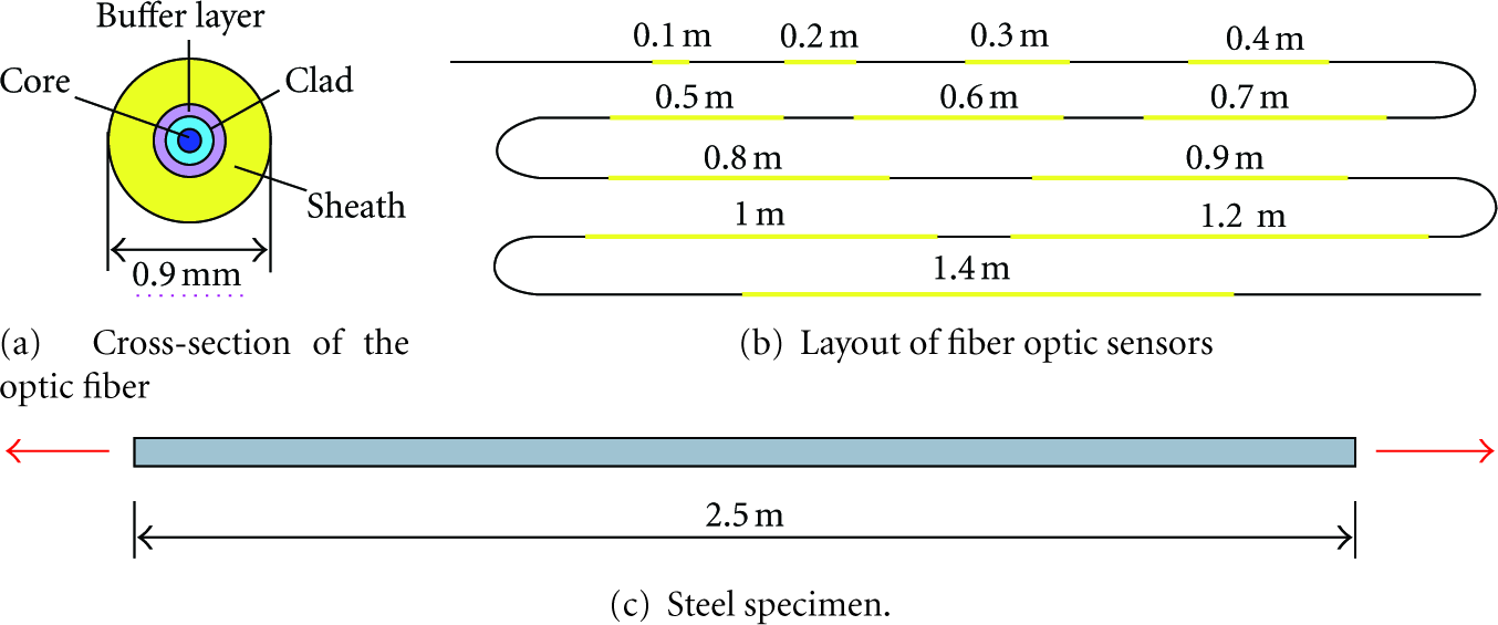
Measurement behavior of fiber optic sensors.
3.2. Measurement Behaviour of a Type 1 Optical Fiber
3.2.1. Strain Profile along a Fiber Optic Sensor
BOTDA monitors the strain profile along the optical fiber with a 5 cm sampling interval. Figure 3 shows the average strain profile of 10 repeated measurements along the whole optical fiber under loading levels of 300, 800, and 1500
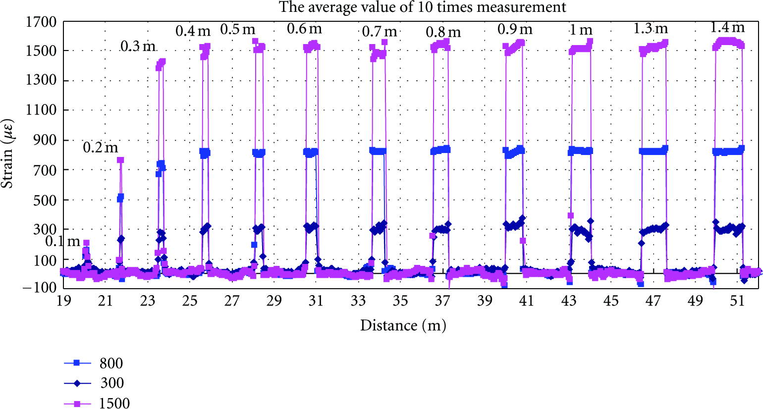
Strain profile along fiber optic sensors.
According to Figure 3, the lengths of the measured strain distributions for different strained FOS segments remain constant at different load levels.
3.2.2. Measurement of the Strain Value of Optical Fibers with Different Sensing Lengths
Under loading levels of 300, 800, and 1500

Measurement values of optical fibers with different sensing lengths.
Despite the nominal accuracy of strain measurement is ±25
Based on Figure 4, one important phenomenon should be noted. Despite the spatial resolution of 10 cm (nominal value), if the length of the strained FOS segment is shorter than 0.4 m, the measured strain value of BOTDA is still less than can be detected with the strain gauge. To explain this phenomenon, the strain ratios between the measured BOTDA value and the strain gauge for different load levels are analyzed, as shown in Figure 5.
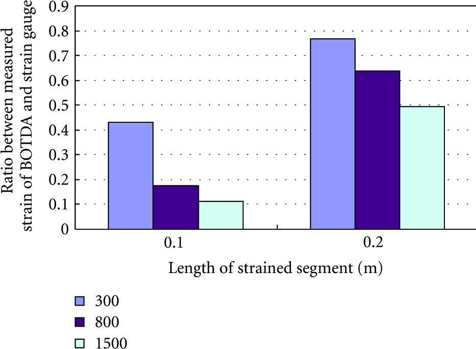
Sensing behaviour of optical fibers.
According to Figure 5, the larger the applied strain, the smaller the strain ratio of the measured value of BOTDA and the strain gauge. Therefore, slippage between the bare fiber and the coating materials may occur. Subsequently, the strain in optical fibers will redistribute, as shown in Figure 6(a), and this strain redistribution lowers the measured strain of BOTDA and results in a measured value of BOTDA below the correct value. At present, the detailed strain distribution of FOS still remains an unresolved problem. Nevertheless, based on the aforementioned analysis, to obtain the correct measured value by using this type of FOS, the length of the strained FOS should be longer than 0.4 m. This length is defined as the critical effective sensing length (CESL).

Strain redistribution in FOS.
If the length of the strained FOS segment is longer than the CESL, after strain redistribution caused by slippage, there still exists upwards of 10 cm (spatial resolution) of uniform strain distribution whose value equals the applied strain value to ensure that the BOTDA system can obtain a correct measurement, as shown in Figure 6(b).
3.3. Measurement Behaviour of a Type 2 Optical Fiber
To check the internal slippage of the FOS, another type of optical fiber (as shown in Figure 7) was adhered to the same tensile steel specimen, and the same experimental procedure was performed. Eight segments with different lengths (0.1 m–0.16 m, 0.18 m, and 0.2 m) are set in series. Under a loading level of 800

Sensing behaviour of the optical fiber (type 2).
According to Figure 7, if the length of the strained segment is longer than 0.16 m, the error associated with the measurement is smaller than 40
3.4. Measurement Behaviour of a Bare Optical Fiber
3.4.1. CESL of a Bare Fiber
For an FOS, if the length of the strained segment of the FOS is shorter than the CESL, the measured strain of BOTDA is less than that of the strain gauge. The actual spatial resolution of BOTDA is greater than 10 cm, which needs to be investigated further. To completely prevent slippage of the FOS, the UV coating of the type 2 FOS is peeled away, and the bare optic fiber is used to directly carry out the same experiment. The experimental results are illustrated in Figure 8.

Sensing behaviour of the optical fiber (bare fiber).
From the experimental results depicted graphically in Figure 8, if the sensing length of the bare FOS is longer than 13 cm, BOTDA can produce the correct measurement. Thus, the CESL of a bare optical fiber can be considered to be 13 cm.
When the length of the strained segment is only 0.1 m, the measurement is exceptionally undervalued, which can be explained. During the measurement, the sampling interval of PPP-BOTDA is 5 cm; generally, the 0.1 m uniform strain distribution is rarely considered exactly within a certain sampling point measurement by the PPP-BOTDA with a 0.1 m spatial resolution. There is a gap between the sampling point of BOTDA and the starting point of the strained segment, as shown in Figure 9. The range of the gap is considered to be from 0 to 2.5 cm. Thus, only the length of the strained bare FOS is longer than 0.125 m, to ensure that at least one sampling point can measure a 10 cm completely uniform strain distribution, and this sampling point can obtain the correct measured value. Therefore, the PPP-BOTDA sensing technique has a spatial resolution on the order of 10 cm.

Gap between the sampling point and the starting point of the strained fiber.
Based on the aforementioned experimental result, different types of FOSs have different CESLs, and the CESL parameter can be used to evaluate the anti-slippage property of FOSs. Obviously, if the FOS has a worse anti-slippage property, the deformation of the strained segment will extend into the range of the adjacent non-strained FOSs. To measure a uniform strain distribution whose value equals the applied strain and is more than 10 cm in length (spatial resolution), the longer strained length is necessary so that the BOTDA system can obtain the correct measurement. Therefore, the longer the CESL is, the worse the anti-slippage property becomes [7].
3.4.2. Measurement Behaviour of BOTDA When the Strained Length of FOS Is Less Than the Spatial Resolution
In our previous investigation on BOTDR [6], when the strained length of FOS is less than the spatial resolution (1 m), the BOTDR device can obtain certain strain values. This characteristic can improve the ability of BOTDR to monitor localized deformation. In this section, an experiment similar to that described in Section 3.1 is used to investigate the measurement behaviour of BOTDA in the case in which the strained length of the FOS is less than the spatial resolution. A bare optical fiber is used in this experiment. The measured results are illustrated in Figure 10.

Strain redistribution in the FOS.
Based on the experimental results, at different load levels when the strained length of the FOS is less than the spatial resolution, the measured results of BOTDA are close to 0 and there is a large variance among the 10 repeated measurements. Consequently, if no internal slippage occurs, the BOTDA system is not able to directly monitor localized deformation whose strained range is less than the spatial resolution.
4. Performance Evaluation of PPP-BOTDA for Crack Monitoring
4.1. Test Method
4.1.1. Specimen
In this study, standard experiments are proposed to calibrate the crack measurement performance of the BOTDA-based distributed optical fiber sensors and to evaluate the accuracy of the measurement. The schematic illustration of the applied standard specimen is shown in Figure 12(a). Two rectangular concrete blocks are connected with two strips of FRP sheets, and the small gap between the two blocks is utilized to simulate an ideal concrete crack. The specimen is axially loaded under a load control mode. Upon loading, the gap becomes wider, and its width is measured by BOTDA-based DFOSs. Simultaneously, the width of the gap is measured by means of displacement transducers (DTs) for comparison.
4.1.2. Bonding Method of the FOS
For different measurement purposes, two installation methods for attaching the optic fiber sensor to the surface of the specimen are proposed and studied. One is termed the overall bonding (OB) method. In the OB method, the necessary measured length of the fiber optic is bonded completely to the surface of the specimen with resin. The OB method is suitable for monitoring strain distribution over a large area. The second installation method is termed the point fixation (PF) bonding method. In the PF bonding method, the two ends of the fiber optic sensor are bonded to the specimen to form a uniform strain distribution within the two bonding points. The measured value of this uniform strain distribution area can be regarded as an average strain value of the gauge length. Consequently, if the gauge length is longer than the spatial resolution, the PF-installed FOS can be effectively used to monitor and measure the crack width of civil engineering structures. Figure 11 schematically demonstrates the OB and PF installation.

OB and PF installation of the FOS.

Experiment specimens.
4.1.3. Placement of the FOS
In the experiment carried out by the author, the two types of optical fiber described previously were used. For the type 1 optical fiber, the gauge lengths of the PF bonding method are 0.2 m, 0.3 m, and 0.4 m, respectively, and for the type 2 optical fiber, the gauge lengths for the point fixation bonding method are 0.1 m, 0.15 m, 0.2 m, and 0.3 m, respectively (Figure 12).
4.2. Performance Assessment
To assess the performance of BOTDA for crack monitoring, the measured DT data are used as a baseline to check the accuracy of BOTDA. The measured DT results for different gauge lengths and different load levels are shown in Figure 13.

DT measurement results.
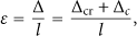
According to Figure 13, two DTs whose gauge lengths are equal to 10 cm give almost the same measured value, and the measured values of the DTs whose gauge lengths equal 20 cm are bigger than the DTs whose gauge lengths equal 10 cm. Thus, this type of deformation can be used to simulate an ideal concrete crack while taking the elastic deformation of concrete block into consideration. The strain on the surface of a concrete structure can be expressed by the following equation:
According to Figure 12, the total deformation over the gauge length of 0.1 m, 0.15 m, 0.2 m, 0.3 m, and 0.4 m can be calculated. Moreover, these deformations over different gauge lengths can be converted to the corresponding strain values and then used to check the test accuracy of BOTDA.
4.2.1. Assessment of the PF Bonding Method
The measured results of type 1 FOS are shown in Figure 14.

Measurement results for the optical fiber (type 1).
With reference to Figure 14, for type 1 optical fiber with a gauge length less than 0.4 m, the measured strain value of BOTDA is smaller than the converted strain of DT; the smaller the gauge length is, the smaller the ratio of the measured strain of BOTDA to the converted strain of the DT becomes. The conclusion for Section 3.2.2 is also applicable here. However, the PF bonding method can only provide the total deformation over the gauge length; the exact position of cracks and the number of cracks cannot be adequately identified.
The measured results for type 2 optical fiber are shown in Figure 15.

Measurement result for the optical fiber (type 2).
Based on Figure 15, if the sensing length of the type 2 optical fiber is longer than 0.2 cm and the measurement of BOTDA agrees with the DT very well, the CESL of the type 2 optical fiber should be longer than 10 cm and less than 20 cm. This conclusion is practically the same as that of Section 3.3.
4.2.2. Assessment of the OB Method
The measured results of the two types of FOSs applied with the OB bonding method are illustrated in Figure 16.

Measurement result for an optical fiber installed by the overall bonding method.
According to Figure 16, for a preset crack width of 0.6 cm (a value much less than the 10 cm spatial resolution), the overall bonding method can reflect the propagation of the crack. Because the sensing region of the optical fiber sensor is bonded completely to the surface of the specimen with epoxy resin, the strain distribution generated in the concrete is thus directly given by the bonded optical fiber. For any occurrence of and propagation of cracks in concrete structures, there must be a debonding between the epoxy resin and the cracked concrete surface, with localized strain occurring on the fiber close to both sides of the crack, as shown in Figure 17(a). In the case of perfect bonding, the fiber would never survive such a large localized strain. Except for the slippage between the optic fiber and the epoxy resin, the optical fiber located at the cracked position is strained and elongated. Moreover, this localized strain peak also causes internal slippage of the optical fiber, and the localized strain peak is distributed near the optical fiber segment. Consequently, the strain distribution of the sensing fiber should be similar to Figure 17(b). However, performing detailed strain measurements close to cracks is still an unresolved problem, and no stable relationship is found between the measured strain from the overall bonding and the converted strain of the DT. Thus, the overall bonding method is still not feasible for monitoring the crack width quantitatively.

Strain redistribution in optical fibers.
According to Figure 17, for a type 2 FOS, because of the good antislippage property, the measured result for the optic fiber installed with the overall bonding method is much smaller than that for type 1 FOS. Thus, for the overall bonding method, the slippage of the FOS is favorable to monitor cracking of the concrete structure. If slippage of the FOS can be completely prevented, the overall bonding method may lead to the rupture of optic fibers and hence lose its ability to reflect the existence of cracks.
5. Comparisons with BOTDR
In our previous investigation [6], the measurement behaviour of BOTDR was discussed and the performance of BOTDR for crack monitoring was evaluated with the same experiment. The PPP-BOTDA sensing technique has a significantly improved spatial resolution; therefore, it is necessary to compare these two distributed fiber optic sensing techniques.
5.1. Monitoring Localized Deformation
The nominal spatial resolutions of BOTDR and PPP-BOTDA are 1 m and 0.1 m, respectively. The improvement in the spatial resolution is good for detecting the localized deformation. For the BOTDA technique, an optical fiber installed with the PF method can be used to monitor cracking or localized deformation. For the BOTDR technique, the optic fiber should be installed with the loop installation method.
5.2. Relation of Truly Measured Strain Distributed Range and Actual Strain Distributed Range (Sensing Length)
For the BOTDR technique, the length of the actual strain distribution can be calculated from the length of the measured strain distribution by using the following equation [6]:

The correctness of (3) was verified by our experiments which are similar as the experiments carried out in Section 3.1. The actual length of the fiber optic sensor installed in the point fixation method is 1.4 m. According to (3), the truly measured length of the optic fiber can be calculated:

Distributed strain data along an optic fiber measured by BOTDR (sensing length = 1.4 m).
For the BOTDA technique, based on the experimental result of Section 3.2, the length of the actual strain distribution also can be calculated from the length of the truly measured strain distribution by using (3); consequently, the truly measured length of optic fiber can be calculated:

Distributed strain data along an optic fiber measured by BOTDA (sensing length = 1.4 m).
6. Conclusions
Based on the experimental results for the bare fiber, the PPP-BOTDA sensing technique has a 10 cm spatial resolution. Despite the 10 cm spatial resolution, if the sensing length of the FOS is less than the CESL because of slippage between the bare fiber and the coating materials of the optic fiber, the BOTDA measurement result will not be correct. Different types of FOSs have different CESLs, and the longer the CESL is, the worse the antislippage property becomes. Point fixation installation methods can give effective and correct measurement results for monitoring localized deformation when the gauge length of the optical fiber is longer than the CESL. The overall bonding method can reflect the existence of cracking or localized deformation, but it is still unfit for monitoring crack width quantitatively. A higher number of repeated measurement counts and smaller scanning steps can improve the measurement accuracy, but these settings can increase the measurement time significantly. An effective way to reduce the error level of BOTDA is to adopt the average values of several time measurements.
Footnotes
Acknowledgment
The authors would like to thank there viewers for their detailed comments that have helped to improve the quality of the paper. This work is supported by the Major Programs of the Chinese Academy of Sciences during the 12th Five-Year Plan Period (no. 2011BAK02B03); the National Natural Science Foundation of China (no. 51208113); Natural Science Foundation of Hebei Province of China (no. E2013210); The Foundation for Development of Science and Technology of Fuzhou University (no. 2012-XQ-33).