
Abstract
In wireless sensor networks, sensor coverage and network connectivity problems are caused by the restricted sensing and communication range of the nodes. To solve these problems, many studies have been undertaken but most of this work is too limited to be applied to real environments because they do not consider various environmental factors that affect wireless sensor network deployment. In this paper, we propose a node deployment strategy that considers environmental factors and the number of nodes for surveillance and reconnaissance sensor networks (SRSNs). Our strategy consists of four steps for the installation of a surveillance and reconnaissance sensor network: the analysis of environmental factors, sensor node deployment, selection of monitoring sites and relay node deployment. It deploys the sensor nodes, and relay nodes while considering features of the surveillance and reconnaissance sensor networks as well as environmental factors. Simulation results show that our strategy improves sensor coverage and network connectivity.
1. Introduction
Wireless sensor networks (WSNs) have been used in various applications, such as forest monitoring, disaster management, space exploration, factory automation, secure installation, border protection and battlefield surveillance [1]. Sensor nodes collect environmental information such as temperature, humidity, seismicity, and acoustics. Relay nodes transfer sensor data to the base station or other nodes.
Most sensor nodes and relay nodes have certain constraints such as restricted sensing and communication range as well as limited battery life. These limitations cause some technical issues in terms of coverage, network connectivity, network lifetime, scheduling, and data aggregation [2]. The problems associated with coverage and connectivity are caused by the limited detection range and communication range between nodes. The coverage problem is essentially how to ensure that the sensor node can cover the entire area it should monitor. One solution to maximize coverage is to deploy sensor nodes not too near to other nodes in order to make the best use of the detection capability of the sensor network and at the same time to deploy the sensor nodes not too far from other nodes so as to avoid the coverage holes [2]. Sensor nodes and relay nodes need to be placed close enough so that they are within each other's communication range to ensure connectivity [2].
Optimal node placement problems are very hard and have been proven to be NP-hard for most formulations of sensor deployment [1]. A lot of research follows a heuristic approach to get near optimal results. The node deployment strategy can usually be divided into static positioning or dynamic positioning depending on whether the optimization is done during node deployment or during network operation. Many researches have been done to propose different approaches for optimal node deployment [1]. However most of the research does not consider various environmental factors affecting the deployment of the sensor network. Therefore, they are too limited when applied to real environments. In this paper, we propose a node deployment strategy that considers environmental factors and the number of nodes for surveillance and reconnaissance sensor networks (SRSNs).
The rest of this paper is organized as follows. In Section 2, we describe surveillance and reconnaissance sensor networks and several existing node deployment schemes. Section 3 describes our node deployment strategy that considers environmental factors and the number of nodes. In Section 4, we evaluate the performance of the proposed node deployment strategy through simulation. Finally, we conclude this paper in Section 5.
2. Related Works
2.1. Surveillance and Reconnaissance Sensor Networks
Surveillance and reconnaissance sensor networks (SRSNs) are one of the most well-known applications of WSN. The SRSNs sense and process nearby information in real time through an autonomous wireless network of tiny sensor nodes which have multisensing capability.
SRSNs consist of sensor nodes, relay nodes, and a C2 (command and control) terminal, as shown in Figure 1 [3]. The sensor nodes have sensors capable of detecting magnetism, seismicity, acoustics, light intensity, and heat. These networks have a self-organization capability that is used to build a network in unfriendly areas, including enemy territory. They also have a self-healing capability to deal with sensor fault or damage. The relay node communicates with the sensor nodes and other relay nodes. The relay node has extended transmission capability as it has more energy resources than the sensor node. The C2 terminal is deployed at the monitoring site in order to control the sensor network in general and has a user-friendly interface for a human operator. Detected data is synthesized, analyzed, and displayed on the C2 terminal.

Configuration diagram of SRSN.
One of the most important characteristics of SRSNs is that it is installed by a human and once installed, a node cannot move itself. Also the number of nodes in SRSNs installation is restricted, and the nodes are often affected by outdoor environmental conditions, such as terrain, climate, and threat [4].
2.2. Node Deployment Strategy
The node deployment strategy decides what type of node is needed and where it should be deployed in order to achieve performance that meets the user's requirements. The goal of node deployment is different in accordance with the role of the node. The goal of sensor node deployment is to maximize the sensing coverage. Coverage can be classified into three types: area coverage, point coverage, and barrier coverage. Most previous works deals with area coverage [1].
Biagioni and Sasaki [5] review regular deployment topology such as hexagonal, rings, and stars. They study coverage and connection properties under normal and partial failure conditions. They argue that regular node placement simplifies the analysis due to its symmetry even if it often leads to suboptimal configurations. Howard et al. [6] propose an incremental deployment algorithm that deploys nodes one-at-a-time into an unknown environment, with each node making use of information gathered by previously deployed nodes to determine its target location. The virtual force algorithm (VFA) uses the concept of attraction and repulsion to maximize the sensor field coverage for a given number of sensors [7]. Butler and Rus [8] developed distributed algorithms for mobile-sensor networks to physically react to changes or events in their environment or in the network itself. This method has the advantage of maximizing the detection rate by relocating sensors in an area near the route of an object. This has the disadvantage of increasing energy consumption by moving whenever an event occurs. Wang et al. [9] proposed a framework for relocating mobile sensors in a timely, efficient, and balanced manner while at the same time maintaining the original sensing topology as much as possible.
There is a study on deploying sensor nodes based not only on the equality of density and distribution but also various other environmental factors such as climate and terrain [10]. However, the proposed method does not properly quantify the effect of environmental factors, and as such, these factors only have a limited effect on node deployment.
The goal of relay node deployment is to maximize network connectivity and operation time. Hou et al. [11] proposed a 2-tier sensor network architecture consisting of sensor nodes and aggregation-and-forwarding nodes (AFN). Sensor nodes transmit data to AFNs and AFNs relay this data. Tang et al. [12] studied the deployment problems of relay nodes connected to all nodes. Lloyed and Xue [13] dealt with model generalization in which relay nodes have longer transmission distances than sensor nodes.
Previous studies for node deployment have made many contributions theoretically, but most of them are difficult to apply in real situations because they do not deal with factors affecting sensor network deployment.
3. Deployment Method for SRSNs
This paper proposes a node deployment method that considers outdoor environmental factors such as terrain, vegetation, and climate, with a limited number of nodes for SRSNs. To consider the characteristics and factors that affect SRSNs, the proposed method has four steps in its installation procedure, these are shown in Figure 2. The installation procedure for SRSNs consists of an analysis of factors affecting node deployment, sensor deployment based on sensing range, selection of the monitoring site, and relay node deployment based on RF communication range. In this section, we describe the proposed deployment method, which is focused on sensor nodes and relay nodes.

Installation procedure for SRSNs.
3.1. Analysis of Factors Affecting Node Deployment
Node deployment is simply a matter of choosing the best locations for the optimal number of sensors to cover the mission area. The node deployment planner should consider various factors that affect node deployment in order to be useful to the user who performs the node placement. The factors affecting node deployment to be considered are mission type, mission area, target type, mission task, sensor type, terrain, vegetation, climate, available number of nodes, communication and intrusion probability among others [14]. In addition, to calculate the node placement, composite factors, which are some combinations of environmental factors, should be considered such as the relationship between sensing range, RF communication range and node deployment type [4]. In Figure 3 the relation of environmental factors and composite factors are shown. Sensor type is selected by considering mission area, target type, mission task, terrain, vegetation, and climate. Sensing range is affected by sensor type, climate, vegetation, and climate. RF communication is affected by terrain, and vegetation.

Relational diagram for environmental and composite factors.
As shown in Figure 3, the node deployment type is related to factors such as mission type, target type, mission work, sensor type, terrain, vegetation, available assets, communication and intrusion probability. The composite factors are all related to each other. Sensing range is the most important factor among composite factors. Most of the other factors affect sensing range directly or indirectly.
Table 1 shows the relations between environmental factors and sensor type. Sensors that are used on the SRSNs can be divided into two types: nondirectional sensors, such as seismic, magnetic and acoustic sensors; and directional sensors, such as PIR, image, and electromagnetic sensors. In Table 1, we use the “S (strong)” relation when sensor is used only in the specific item. The “-(none)” relation means that sensor is used commonly in various items. As shown in Table 1, environmental factors have different influences on different sensor types. In fact, directional sensors are more sensitive to environmental factors than nondirectional sensors. These relations must be considered during node placement [15].
Relations between environmental factors and sensor types.
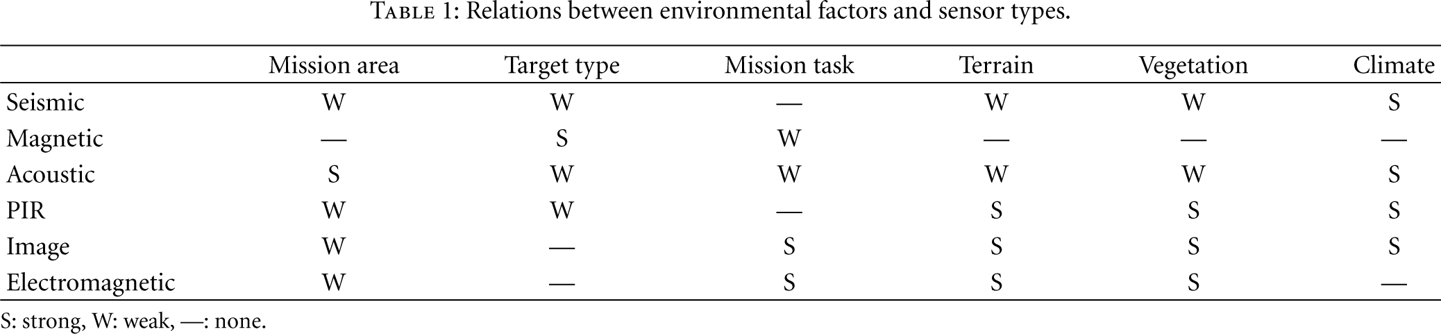
S: strong, W: weak, —: none.
The first step in SRSNs deployment is to analyze environmental factors through intelligence preparation of the battlefield (IPB) data. The IPB process provides the key elements to support SRSNs planning, including identification of entry points, lines of communications, threat avenues of approach, designation of NAIs (named areas of interest) and evaluation of line-of-sight communication conditions in the area of operations. When this process is completed, the planning cell will have a detailed understanding of the influence of terrain, weather, and enemy forces on sensor employment. It will have also identified potential locations for sensor nodes, relay nodes, and monitoring sites.
Terrain data for IPB analysis are satellite images, military maps, DTED (digital terrain elevation data), VITD (vector interim terrain data), and so forth. As the sensing range of the sensor nodes used in SRSNs is in the dozens of meters, the scale of terrain data should be at least 1 : 1000.
3.2. Deployment of Sensor Node Based on Sensing Range
The strategy we employ for sensor node deployment is to find an optimum deployment that minimizes the cost function by considering the impact of environmental factors on sensor node performance. The approaches to find an optimum deployment utilizes the global search method such as genetics algorithms and simulated annealing, a destructive method to remove excessive sensors until a local minimum point is found, and a constructive method, in which sensors are individually placed until the cost function has reached a minimum [14].
This paper aims to develop a method to determine the location of sensor nodes to maximize sensor coverage while satisfying a given constraint condition. The constraint assumed in this paper is the fact that the number of sensor nodes is limited. Our approach is to build an optimal model based on integer programming [16]. Assuming that one cell is covered by one sensor node and the size of the cell is limited by the RF communication range of that sensor node. Every sensor node is assumed to have the same performance, but its coverage is different due to different environmental factors.
Figure 4 shows the flow chart for the sensor node deployment algorithm based on sensing range. After the system gets input factors such as number of sensor nodes, terrain, vegetation, climate of the mission area, it calculates the weights that affect sensor node deployment. We can use the following formula to compute the sensing range

where

where

Flowchart of sensor node deployment algorithm.
We compare
Figure 5 shows the adjustment of cell size through merging a certain amount of basic cells. The number of merged cells,

where the variable n is the number of cells to be merged, in width or in length.

The adjustment of cell size.
As shown in Figure 5, A is composed of one cell. B is composed of 4 cells. C is composed of 9 cells. D is composed of 16 cells. The size of the cell can be adjusted to fit number of sensor nodes.
When the cell size is adjusted, the RF communication range of the sensor nodes should be considered.

Another method to adjust cell size is to use the intrusion probability of targets. In this we use a sparse deployment in areas of low intrusion probability by enlarging cell size, and dense deployment in areas of high intrusion probability by reducing cell size. The cell area,

where
Each sensor node in a grid-based deployment sets the positioning area of the sensor node inside the cell. The positioning area is set as a square which has a side length of
If
If the location of the sensor node is changed, coverage redundancy problem occurs. In order to minimize this redundancy, the algorithm should be modified. As shown in Figure 6, by segmenting the positioning area of a sensor node, assigning different weights (

The method of minimizing the coverage redundancy.
3.3. Selection of Monitoring Site
The position of a monitoring site is decided on the basis of various considerations. The most important consideration is to ensure line-of-sight communication. Second, the monitoring site should be far from the sensor field in order to secure response time in the event of an enemy intrusion. Third, the monitoring site should have the ability to provide sensor data to the supported unit immediately. Other important considerations in site selection are security, accessibility, and supportability.
3.4. Deployment of Relay Node Based on RF Communication Range
The strategy for relay node deployment is established by defining three principles in terms of operational efficiency and energy consumption. First, after the relay node is connected to the C2 terminal, it is then connected to the sensor nodes. Second, a direct connection between the relay node and the C2 terminal is the top priority. When a direct connection is not possible, a multihop connection with neighboring relay nodes is established. Third, a direct connection between the relay node and sensor node should be also guaranteed. When a direct connection is not possible, a multihop connection with neighboring sensor nodes is established. One relay node is allocated per basic unit of the sensor nodes. The initial location of the relay node is at the centroid of the sensor node cluster. Figure 7 shows the flowchart of the relay node deployment algorithm based on RF communication range. First, the algorithm identifies the possibility of a direct connection between the relay node and the C2 terminal using the communication radius

where

Flowchart of the relay node deployment algorithm.
As shown in Figure 8, the positioning area of the relay node is determined by the rectangle of the basic unit of the sensor nodes. If the location of the relay node is adjusted within the whole positioning area but it is not connected to the C2 terminal directly, it should be connected to the C2 terminal via a neighboring relay nodes or additional relay nodes. In the case of a connection to the C2 terminal via neighboring relay nodes, if a direct connection between the relay node and a neighboring relay node is possible, the optimal position of the relay node is decided by considering the number of one-hop connections between the relay node and sensor nodes. In the case of a connection to the C2 terminal by additional deployment of relay nodes, if a direct connection between the relay node and additional relay nodes is possible, the optimal position of the relay node is decided by considering the number of one-hop connections between the relay node and sensor nodes.

Positioning area of relay node.
If a direct connection between the relay node and the C2 terminal is available, the algorithm checks the connection between the relay node and the sensor node. At first, it calculates
If the relay node is moved in the whole positioning area and
After the relay node is connected to the C2 terminal, it should be connected to the sensor nodes. Figure 9 shows the flowchart for the connection between relay nodes and sensor nodes. If the connection between the relay node and sensor nodes is possible with one-hop, they are connected directly. If this is not possible, the connection possibility is decided with the neighboring sensor nodes. If a multihop connection with neighboring sensor nodes is possible, it is connected within the given hop range. If it is not possible to connect the relay node with neighboring sensor nodes, an additional sensor node should be deployed to make the connection possible, or the node that failed to connect should be excluded.

Flowchart for the connection between relay nodes and sensor nodes.
4. Performance Evaluation
To evaluate the performance of the proposed method, simulations were performed by using Global Mapper Version 9.03 and real geographical data. The sensing and communication range were computed while considering terrain, vegetation and climate with Global Mapper. In this paper, we use sensor node coverage and network connectivity as performance metrics, and compare the deployment results. First, sensor nodes are placed at square grid points which consist of basic cells, the sensor node is located at the center of each cell. Then, the proposed sensor node deployment algorithm in Figure 4 is executed in order to place sensor nodes at optimal positions.
DTED (digital terrain elevation data) is used in the experiment area. The area is
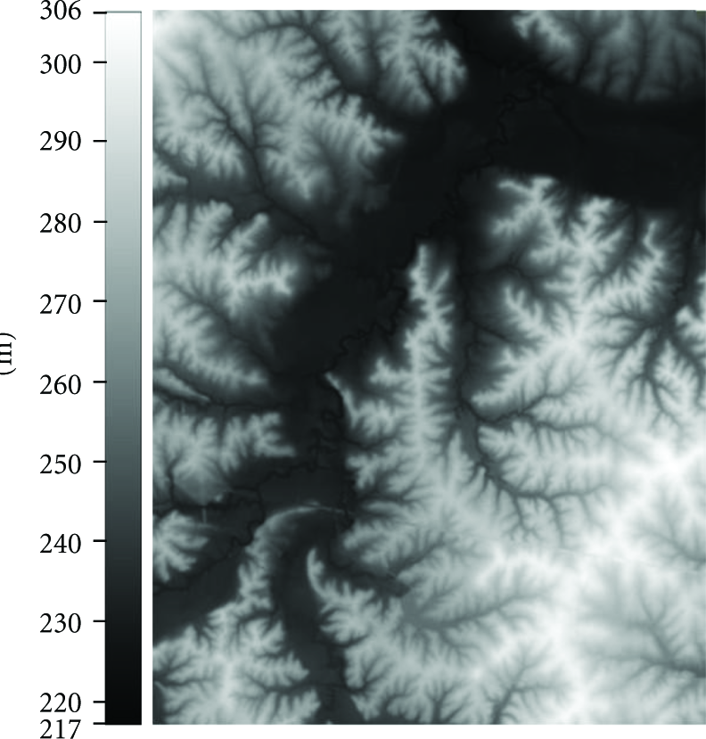
DTED in experimented area.
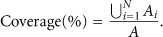
To evaluate the performance of the proposed deployment algorithm for sensor nodes, the coverage at the initial and final locations of the sensor nodes are compared. A 360 degree detectable PIR (passive infrared) instrument is used to evaluate the coverage in terms of the line of sight. Coverage is computed by (7) [17].
The geographical data in the experiment area is represented in a 7 × 8 grid on the basis of the detection range computed by the analysis of environmental factors. Figure 11(a) shows the coverage for the initial location of the sensor nodes. Figure 11(b) shows the coverage for the final location of the sensor nodes. As shown in Figure 11, the areas with high-elevation changes have much lower coverage than the plains. The average coverage for two locations is summarized in Table 2. The coverage for the initial layout is 42.8%. The coverage of the final layout is 63.7%. Coverage is improved by 20.9%.
Sensor node coverage.


Coverage before and after the adjustment of sensor node location.
Another simulation was performed for when the number of sensor nodes is less than that of basic cells, and as such cell merging is required. After 4, 9, or 16 basic cells are merged, the coverage is compared before and after the location adjustment of the sensor node. After merging the cells, the average coverage of the initial deployment and final deployment is computed and the result is shown in Figure 12. It can be seen that the coverage decreases exponentially as the cell size gets bigger. The location adjustment of sensor nodes improves the coverage.
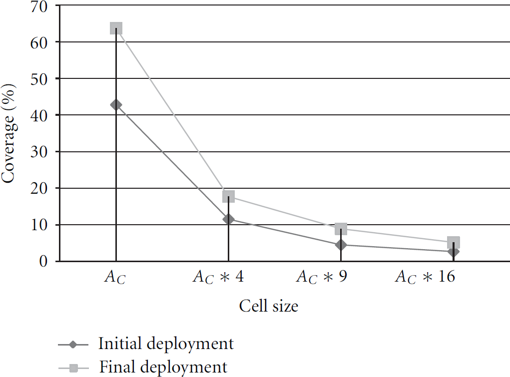
Average coverage for each cell size.
After finalizing the location of the sensor nodes, the experiment for connectivity between the sensor node and relay node was performed. Clusters are composed of 9 sensor nodes in one unit. For each cluster, one relay node is allocated. There are 36 sensor nodes and 4 relay nodes. The radio frequency was set to 400 MHz. The curvature of the earth was not considered. Figure 13 shows the communication range of the relay node on top of the coverage of the sensor node depicted in Figure 11(b). The relay node is placed initially at the center of the cluster. Figure 13(b) shows the relay node in an optimal position. For each cluster, the communication range after the location adjustment is wider than before. The results are shown in Table 3. In the initial location, the number of one-hop connected sensor nodes to the relay node was 4. After adjusting the location, the average became 5.8, an improvement of 45%.
Average number of one-hop connected sensor nodes to relay node.

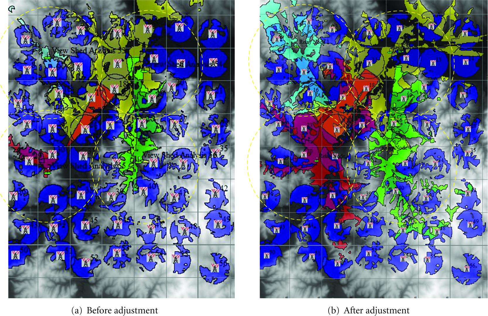
Communication range before and after the adjustment of the relay node.
5. Conclusion
In this paper, we proposed a node deployment strategy that considers environmental factors and a limited number of nodes for surveillance and reconnaissance sensor networks (SRSNs). Our strategy consists of four steps: the analysis of environmental factors, sensor node deployment, selection of monitoring site, and relay node deployment. It deploys the sensor nodes and relay nodes while considering the features of SRSNs and certain environmental factors. Simulation results show that the coverage and network connectivity are improved by 20.9% and 21%, respectively.
In future, we will experiment with more sophisticated conditions for the proposed deployment method, and further develop the algorithm to consider target detection rate. We will also apply the algorithm in the mission plan of the C2 terminal and ensure that node deployment is automated.
Footnotes
Acknowledgments
This work was supported by the Dual Use Technology Program (UM09021RD1). It was also supported by the Research Grant of Kwangwoon University in 2012.