
Abstract
IEEE 802.16j is an amendment to the IEEE 802.16 broadband wireless access standard to enable the operation of multihop relay stations (RSs). It aims to enhance the coverage, per user throughput of IEEE 802.16e. Comparing with a base station (BS), RS does not need a wireline backhaul and has much lower hardware complexity. Moreover, using RSs can significantly reduce the deployment cost of the system. Unfortunately, there are some tradeoffs in the case of multi-hop RSs. Subscriber stations (SSs), located in a long distance, are suffered from the bottleneck of multi-hop, throughput degradation, and increasing of end-to-end delay. This paper proposes a network coding-based relay scheme for multi-hop relay networks, called NC-BR. It allows RSs to combine two wireless backhaul transmissions into one using the network coding technique. This paper also proposes an improved OFDMA frame structure design for the multi-hop relay network. This technique provides higher utilization for the relay zone by reorganizing the RSs transmission sequence. The analysis and simulation results confirm that the proposed scheme can enhance the throughput gain up to 140% and reduce the end-to-end delay by up to 83%. The simulation results also show that the proposed scheme can reduce the jitter by up to 58%.
1. Introduction
The WiMAX technology is becoming more popular as the sharply increasing numbers of service providers those who deploying WiMAX for their new wireless broadband services. The newly IEEE 802.16j standard is to focus on mobile multihop relay networks that enable multihop communication in IEEE 802.16e networks [1]. In multihop relay network, one or more mobile stations (MSs), or subscriber stations (SSs) may communicate with relay stations (RSs) instead of communicating directly with multihop relay support base stations (MR-BS). IEEE 802.16j is an amendment to the IEEE 802.16 broadband wireless access standard to enable the operation of multihop relay stations. It aims to enhance the coverage, per user throughput and system capacity of IEEE 802.16e [2]. Comparing with a base station (BS), the RS does not need a wire-line backhaul; additionally, it has much lower hardware complexity. Thus, using RSs can significantly reduce the deployment cost of the system.
In the IEEE 802.16j multihop relay network, MSs, those connect to the RS located two or more hops away from the MR-BS are suffered from throughput degradation and end-to-end delay increase [3–8]. As the number of RS hops increase, the degradation and the delay grow. Therefore, these problems are two major problems in the IEEE 802.16j multihop relay network.
There are two main reasons that are the cause of highly degradation of both throughput and delay in the IEEE 802.16j network. First is the multihop characteristic that causes an increasing delay and degrading the throughput when the number of RS hops increases. And second, the signal interfere limitation for each RS hop causes a lower utilization in the relay zone when the number of RS hops increases.
The frame structure of the IEEE 802.16j standard document [1, 4, 5] supports two approaches. The first approach allows one or more RS or MR-BS frames to be grouped into a multiframe with a repeating pattern of allocated relay zones. This approach causes limitation to the relay zone utilization, especially on over the 3 hops scenarios. The second approach enables a single-frame structure consisting of more than one relay zones. This approach is appropriated to accommodate the network coding. However, the more the RS hops increase, the more the relay zones of RSs and MR-BS need to stay in the idle mode. This will lead to lower the frame structure utilization and cause throughput degradation.
It is the truth that the SSs who connect to the RS with two or more hops located in a long distance measured from the MR-BS, are suffered from the bottle-neck of multihop, throughput degradation, and increasing of end-to-end delay. These interesting problems may cause some serious situation for particular applications over the wireless multihop network.
Therefore, numerous solutions have been proposed where [4, 6, 7] are trying to modify the frame structure design. The [8] have only done some useful performance comparison of difference frame structure design but have not proposed practical solution. Solution in [9] is trying to modify frame structure only, but, unfortunately, the throughput and the delay improvement are only based on unrealistic internet network traffic. Until now, the problems are partially solved, and the problems remain challenge.
In this paper, the preliminary results have been introduced [10, 11]; a network coding-based relay scheme, called NC-BR, and the new frame structure design are proposed. The proposed NC-BR scheme allows RS to combine two sets of data in the wireless backhaul using the XOR operation and transmit it in a single transmission instead of two. Consequently, the throughput, the delay, and jitter are significantly improved. In addition, the proposed new frame structure design reduces both of the number of transmissions from RSs and the number of idle periods caused by the limitation of signal interference which is considered as a waste. So, the throughput, the delay, and jitter of the network can be significantly improved using the proposed method.
The term jitter, sometimes referred to as a packet delay variation (PDV), is often used as a measure of the variability over time of the packet latency across a network. Jitter is the difference in end-to-end delay between selected packets in a flow with any lost packets being ignored. This is an important quality of service factor in assessment of network performance. Since the proposed NC-BR scheme in this paper improves the delay of the network, it also improves the jitter because variation of packet delay is reduced.
The rest of this paper is organized as follows. In Section 2, the reviews about the background of both IEEE 802.16j multihop relay network and the network coding with the related works are described. Then, Section 3 reviews the two major performance problems in the IEEE 802.16j multihop relay network while Section 4 proposed the new network coding scheme and the design of the supporting frame structure. The analysis of the throughput and the delay of the proposed scheme, including the comparisons among the proposed solution and the existing methods, are performed in Section 5. The experimental results obtaining by simulation and the conclusion are drawn in Sections 6 and 7, respectively.
2. Background and Related Work
2.1. IEEE 802.16j Multihop Relay Network
2.1.1. IEEE 802.16j Standard
IEEE 802.16j is an amendment to the IEEE 802.16 standard that enables the functionalities of interoperable RSs and BSs. In this section, the key system features of the IEEE 802.16j MR network are summarized.
The basic system architecture considered by IEEE 802.16j is shown in Figure 1, where two types of radio links are identified: an access link and a relay link. BS that is capable of supporting the multihop relay is called the MR-BS. The access link is the radio link that originates or terminates at an MS, which is either a downlink (DL) or an uplink (UL), defined in IEEE 802.16-2004. The relay link is the radio link between an MR-BS and an RS or between a pair of RSs; this link can be either UL or DL.

IEEE 802.16j multihop relay network.
Each DL subframe and UL subframe is divided into an access zone and a relay zone. The DL/UL access zone is a portion of the DL/UL subframe used for access-link transmission, and the DL/UL relay zone is a portion of the DL/UL sub-frame used for relay-link transmission. Note that each DL/UL sub-frame may have more than one relay zone.
In order to enable RS operations with no change on the legacy MS specification, two types of RSs have been defined: nontransparent RS and transparent RS. The nontransparent RS acts as a BS sector; therefore, the MR-BS has to assign a preamble index to each RS, and the RS transmits its own preamble, FCH (Frame Control Header) and MAP over the access zone.
When an MS communicates with a nontransparent RS, it will receive a preamble, FCH, MAP, and a data burst from the RS. On the other hand, if an MS communicates with a transparent RS, it will receive the data burst from the RS but will receive the preamble, FCH, and MAP from the MR-BS. Therefore, the transparent RS has to be centralized controlled by the MR-BS to transmit/receive the data burst over the designated subchannels and symbol times. Note that the MR-BS and multiple RSs can serve a particular MS simultaneously so as to increase the received signal quality and to obtain cooperative diversity gain.
Consider the nontransparent RS, it can generate its own FCH and MAP without the instruction from the MR-BS. So the de-centralized control can be performed to reduce the messaging delay and the messaging overhead over relay links. Meanwhile, a group of RSs may transmit the same preamble, FCH, MAP, and the data burst; these RSs will act as a single virtual station from MS's point of view. In this situation, the MS will not initiate the handover procedure when moving between the grouped RSs. Moreover, the cooperative diversity gain will be obtained.
2.1.2. Benefit of Relay Station
RS aims to enhance the coverage, per user throughput of IEEE 802.16e. Compared with a base station (BS), RS needs not to have a wireline backhaul. Additionally, it has much lower hardware complexity. Thus, using RSs can notably reduce the deployment cost of the system. Unfortunately, there are some tradeoff in the case of the multihop relay network since subscriber stations (SSs), who connect to the RS that 2 or more hops away from the MR-BS, are suffered from the bottle-neck of the multihop, end-to-end throughput degradation and increasing of end-to-end delay. By applying proposed NC-BR, the network coding helps RSs transmit more data in the relay link, results are to relief both optimal offered load point and bottle-neck point. More details are described in the following section.
2.2. XOR Network Coding
The network coding is first introduced in [12]. It extends the traditional routing paradigm by allowing interior network nodes to perform coding operations rather than just routing. It has been shown in [12, 13] that network coding can help a communication system achieve multicast capacity in lossless networks. Network coding has recently been applied to wireless networks [14, 15].
The application of network coding in wireless networks is facilitated by the broadcast nature of wireless medium. The best studied case is a three-node topology where two terminals wish to exchange mutual information through an intermediate relay. By applying network coding and utilizing broadcast capability at the relay, [10] demonstrated that the time it takes to exchange a message can be reduced from four-time slots of native transmission to three [16], extend, this idea to multiple terminals, and implemented a practical protocol which uses overhearing and opportunistic packet combining. Their work also showed remarkable throughput increase brought by network coding and physical-layer broadcast.
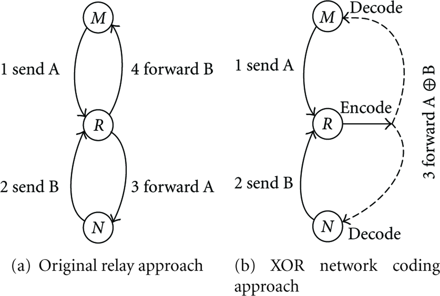
Figure 2 shows a simple example of the XOR network coding. Where in Figure 2(a) it represents the current relay approach, node M and N want to exchange a pair of packets via a router R. Node M sends their packet to the router R, which forwards it to node N, and node N sends their packet to the router R, which forwards it to node M. This process requires four transmissions. Now consider a network coding relay approach. M and N send their respective packets to the router R, which XOR-s the two packets and broadcasts the XOR-ed version. M and N can obtain each other's packet by XOR-ing again with their own packet. This process takes three transmissions instead of four. Saved transmissions can be used to send new data, increasing the wireless throughput, and also decrease the end-to-end delay.
Example of XOR network coding.
3. Problem Statement
The IEEE 802.16j multihop relay network is based on the scheduling scheme. In centralized scheduling mode, all SSs and RS are determined by DL/UL map from the scheduler at a MR-BS, when they transmit, receive, or stay idle. However, there is a slightly difference in the distributed scheduling mode; RSs can create their own DL/UL map and distribute to their connected SSs. The two important problems in the IEEE 802.16j multihop relay network is that every SS which connects to the RS with 2 or more hops away from the MR-BS will be suffered from the bottleneck of multihop. As a consequence, end-to-end throughput degradation and increasing of end-to-end delay occur. For the throughput degradation problem, it is effect from the saturated network situation in the relay zone. The relay zone is a channel that allows the communication between the MS-BS and the RS or the RS to the subordinate RS.
The same problem with other wireless multihop networks also occurred in the 802.16j multihop relay network, due to the multihop network aligns like the line topology. Since each relay has obligation to forward traffic to both UL and DL, this situation creates a bottle-neck in the relay link on the multihop network. In a high traffic loads, the relay link is the cause of saturation of all multihop networks. So, the throughput will largely degrade [17] and even more on the farer hops relay.
Considering all SSs that connected to the RS that two or more hops away from the MR-BS, these SSs will be suffered from the bottle-neck of multihop end-to-end throughput degradation. These highly degradations of both throughput and delay in IEEE 802.16j network are the effects of two factors. The first factor is the multihop characteristic because it causes an increasing delay and degrading the throughput when each number of RS hops was increased. The second factor is the limitation of signal interference of each RS hop. This limitation leads to a lower utilization in the relay zone when the number of RS hops increased.
The rest of this section is organized to 2 parts. The first part illustrates factors that have impacts on the throughput degradation. Then, the second part explains the composite delay that increases the end-to-end delay. Then, the performance analysis of each throughput problems and the delay is provided in Section 5.
3.1. Throughput Degradation Factors
The number of bits passing through a communication channel in a certain period of time, called as throughput, is very important because some services require a high throughput rate in order to prevent a critical loss. Therefore, the factors that affect to the number of throughput rate must be seriously considered. In IEEE 802.i6j multihop relay network, there are two important factors that lead to the degradation of throughput as described below.
3.1.1. Multihop Characteristic
The saturated network in other wireless multihop network had been studies in the past [16, 18]. When the offered load increase through the multihop wireless network, the end-to-end throughput will, respectively increase until the peak throughput point is reached. The peak throughput point is named as the optimal offered load, and the offered load beyond this point is unsustainable; moreover, the throughput will start dropping. In the IEEE 802.16j multihop relay network, this optimal offered load also exists. In the general case, this optimal offered load point is also controlled by the bottle-neck situation of the relay zone too.
Start with bottle-neck situation that will occur to the relay zone between a RS and a MR-BS/superordinate RS, when the traffic load of all SSs that connected to the considered RS and their subordinate RSs exceed the maximum traffic loads over the relay zone. In a general case in the line chain of RSs, the bottle-neck situation is usually occurring at the relay link between a MR-BS and a RS1. This bottle-neck at the relay zone becomes another limitation to the offered load. The end-to-end throughput in the IEEE 802.16j multihop relay network depends on the minimum load between the optimal offered load point and bottle-neck point. Thus, by applying the proposed NC-BR, the network coding can support RSs in transmitting higher data rate over the relay link. Consequently, both optimal offered load point and the bottle-neck point are relieved. More details are described in the next section.
3.1.2. Signal Interference Limitation
Referring to Figure 1, all RSs connected in a chain topology alike in which all RSs use wireless connection as a backhaul. In a simple configuration, each RS transmitting range is just about to cover its superordinate, subordinate RS and MSs. In order to transmit, each RS needs to be in the transmitting mode. Consequently, their superordinate and subordinate RSs have to be in the receiving mode to avoid the signal interference. Therefore, the MR-BS scheduler has an obligation to determine transmission turns for each RS. Accordingly, when the number of hops increases, the transmission time interval for each RS will be arisen, and finally the network utilization will be dropped. In order to solve this problem, a study of reusing frequency channels had been proposed [19]. Unluckily, the result indicates a small improvement of utilization. Figure 3 shows simple nontransparent frame structure transmission turns for the IEEE 802.16j multihop network under 5 hops, according to the latest draft document from the 802.16j task group [2].

Transmission sequence in nontransparent frame structure of 5 hops IEEE 802.16j multihop network.
3.2. Composite-Delay Factors
Beside the throughput degradation problem, there is another issue that must be focused, the end-to-end delay. In the 802.16j multihop network, similar to various wireless multihop networks, each hop of the relay is the cause of an additional time for the end-to-end delay with a traffic flow thru. Besides, the minimum of the additional delay is the size of frame duration of a RS. So, the connected SSs are also suffered from this additional delay, according to the fact that many hops go away from the BS, many delays are added.
Thus, to make a clear understanding of the end-to-end delay over the IEEE 802.16j multihop network, two main delay values must be counted: a multihop delay, and a traffic flow delay.
3.2.1. Multihop Delay
A multihop delay, the traffic flow transmitted thru the number of the MR-BS and RSs until reaches the MS, is related to the wireless multihop characteristic. At each RS, the time that the RS needs to process a set of data and forward to the destination is called an operational delay, while the time for a signal transferring between RSs and from MR-BS/RSs to their connected MS is called a propagation delay on a relay link and a propagation delay on an access link, respectively.
3.2.2. Traffic Flow Delay
When a network is saturated, RSs are unable to clear all data in their forward queues. In this case, the data becomes a backlog in the RS forward queue, and the end-to-end delay is certainly increased. This type of delay stated as a traffic flow delay. This traffic flow delay occurs in a relay link and associated to the bottle-neck position. In the relay link, multiple traffic flows of all sub-ordinate RSs are sharing the same relay link bandwidth which is so inadequate. The traffic flow delay can be defined by the time needed to be cleared out from the backlog data thru a specific relay link at each RS.
This paper proposed a network coding-based relay, called the NC-BR mechanism. Moreover, the frame structure of this mechanism is proposed. The performance analysis had been performed, and the simulation results show that the proposed strategies help reducing both throughput degradation and additional end-to-end delay problems. Moreover, the jitter value in the IEEE 802.16j multihop relay network is also small, which is beneficial to real-time services over the multihop network.
4. NC-BR Mechanism
4.1. Overview
In this paper, the NC-BR mechanism and the structure of its frame support a XOR network coding approach. This will allow an RS to combine 2 sets of data using XOR operators, then transmit all together as a single transmission. The set of data that the RS can combine is obtained from the data that the RS has to transmit to its super-ordinate RS/MR-BS and to its sub-ordinate RS. This approach can reduce number of transmission between hops; thus, the number of idle periods effected from the limitation of signal interference is reduced. Therefore, the throughput and delays of the network can be greatly improved.
In order to describe the NC-BR mechanism, the definition of RS that is capable to be a NC-BR node in IEEE 802.16j multihop relay network is drawn below.
Definition 1.
Let three nodes of RSs (or 1 MR-BS with 2 RSs) be the super-ordinate node ( The superordinate node, MR-BS or RS node is the super-ordinate node if and only if it communicates with the center node,
The center node, RS node is the center node if and only if it communicates with the super-ordinate node,
and its communication with the sub-ordinate node,
The sub-ordinate node, RS node is the sub-ordinate node if and only if it communicates with the center node,
4.2. NC-BR Operations
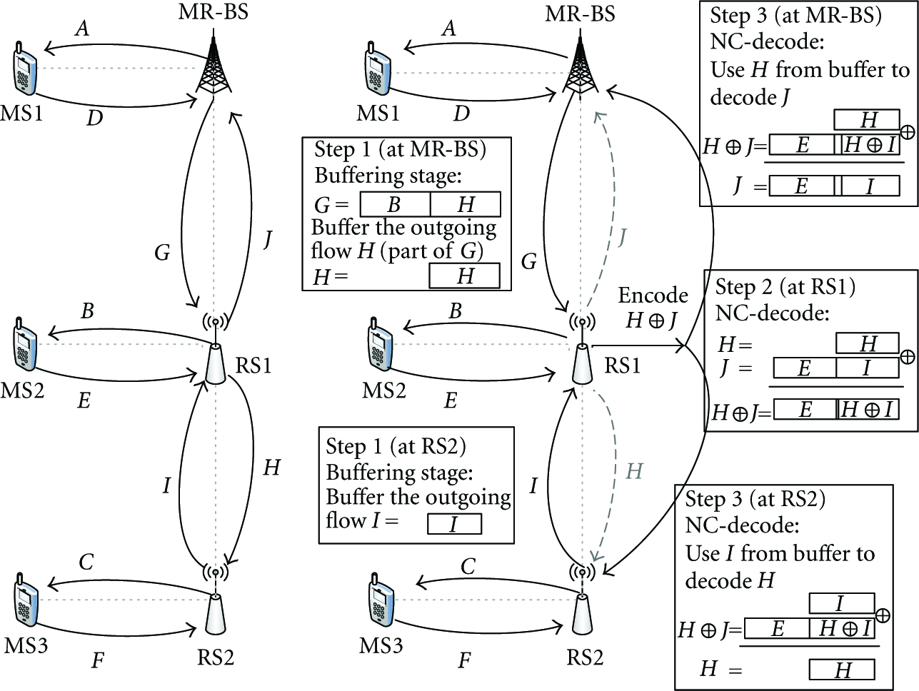
Referring to Figure 4, simple transmission procedures are drawn. Figure 4(a) shows the original RS traffic flows, and Figure 4(b) shows the traffic flows of the proposed NC-BR. According to Figure 4(a), the operations of RS1 are (1) to receive the traffic flows G and I and (2) to transmit the traffic flows J and H. While the operations of RS1 in Figure 4(b) were modified to receive the traffic flows G and I, then they transmit only one encoded traffic flow which is
The NC-BR overview.
The contribution of this approach is that the XOR network coding technique is applied; so there is no extra hardware required because of its simplicity. Additionally, the XOR network coding technique has been proven that the network coding definitely has practical benefits and can substantially improve wireless throughput of store-and-forward behavior.
This operation is responsible for encoding two traffic flows that are transmitting to both super-ordinate and sub-ordinate RS, using the XOR operation at the MAC frame level. In order to integrate and encode data of 2 traffic flows, the NC encoder uses only the data stored in the relay zone, the FCH, and R-map are let unencoded.
Generally, the traffic flow to a super-ordinate and a sub-ordinate RS might have different amount of data in each MAC frame; the NC-encoder will add the padding character to the shorter traffic flow, in order to equalize their MAC frames. The two sets of data that are encoded at the RS1 came from the opposite directions; additionally, each node keeps the last transmitted data frame for the further decoding process.
Considering the NC-BR process, it spans over three MAC frames at time t (i.e., frame t,
Step 1 (Buffering Stage).
The buffering stage is occurring at the super-ordinate node and the sub-ordinate node. It aims to buffer the outgoing data flows (or a part of data flows) of the super-ordinate node and the sub-ordinate node after its transmitting to the center node. These buffered data flows are applied in the decoding process of the super-ordinate node and the sub-ordinate node for the XOR encoded data from the center node in Step 3. Let Let F be a set of all data flows to the center node, i. Let Definition 2.
To be able to decode in Step 3 at time
Let
For example that in the frame t of Figure 4, the MR-BS transmits the flow G to the RS1, and the RS2 transmits the flow I to the RS1. The MR-BS and the RS2 need to buffer the outgoing data of the flow H (a part of G) and the flow I, respectively. This allows both the MR-BS and the RS2 to decode the traffic from the RS1 in Step 3.
Step 2 (NC Encode).
The NC-encode stage of the center node aims to combine a set of data flows to the super-ordinate node and subordinate nodes as a single outgoing flow. Since the wireless network transmission is broadcast, both super-ordinate and the sub-ordinate node can overhear the center node transmission. This stage let the center node combine the data flows by the XOR operation and transmit in a single transmission. Let i be the center node, let j be the super-ordinate node, and let k be the sub-ordinate node. Let Let Let Let Let Definition 3.
Definition 4.
Step 3 (NC Decode).
The NC-decode stage is occurring at the super-ordinate node and the sub-ordinate node. It aims to decode the incoming XOR encoded data flows, or part of data flows, from the center node. The decoding operation in this stage is performed by XORing the incoming data flows with the appropriate buffer data from Step 1. Since Let In the frame At the MR-BS, the encoded flow Similarly, the RS2 received the same Figure 7 shows the detail of NC-BR operations including the operations made by each RS hop. This is to prove that, after two first frames, the NC-BR operations can consistently and endlessly operate over the time.Definition 5.

4.3. NC-BR Frame Structure
The frame structure design is an essential part of the IEEE 802.16j multihop relay network. Most problems mentioned in the multihop data transfer problem are related to the frame structure design. This research proposes a new improved frame structure that supports the NC-BR mechanism. Thus, the NC-BR mechanism has greatly improved the network throughput and reduced both delay as well as jitter values.
Referring to the original transmission process in the multihop relay network, only one station will receive data at a time. In contrast, applying the NC-BR on all RSs, every super-ordinate and sub-ordinate of RSs will be able to receive data from a single transmission. Consequently, the transmission pattern has been changed and much efficient, in addition to gaining benefits according to the higher utilization in the relay zones.
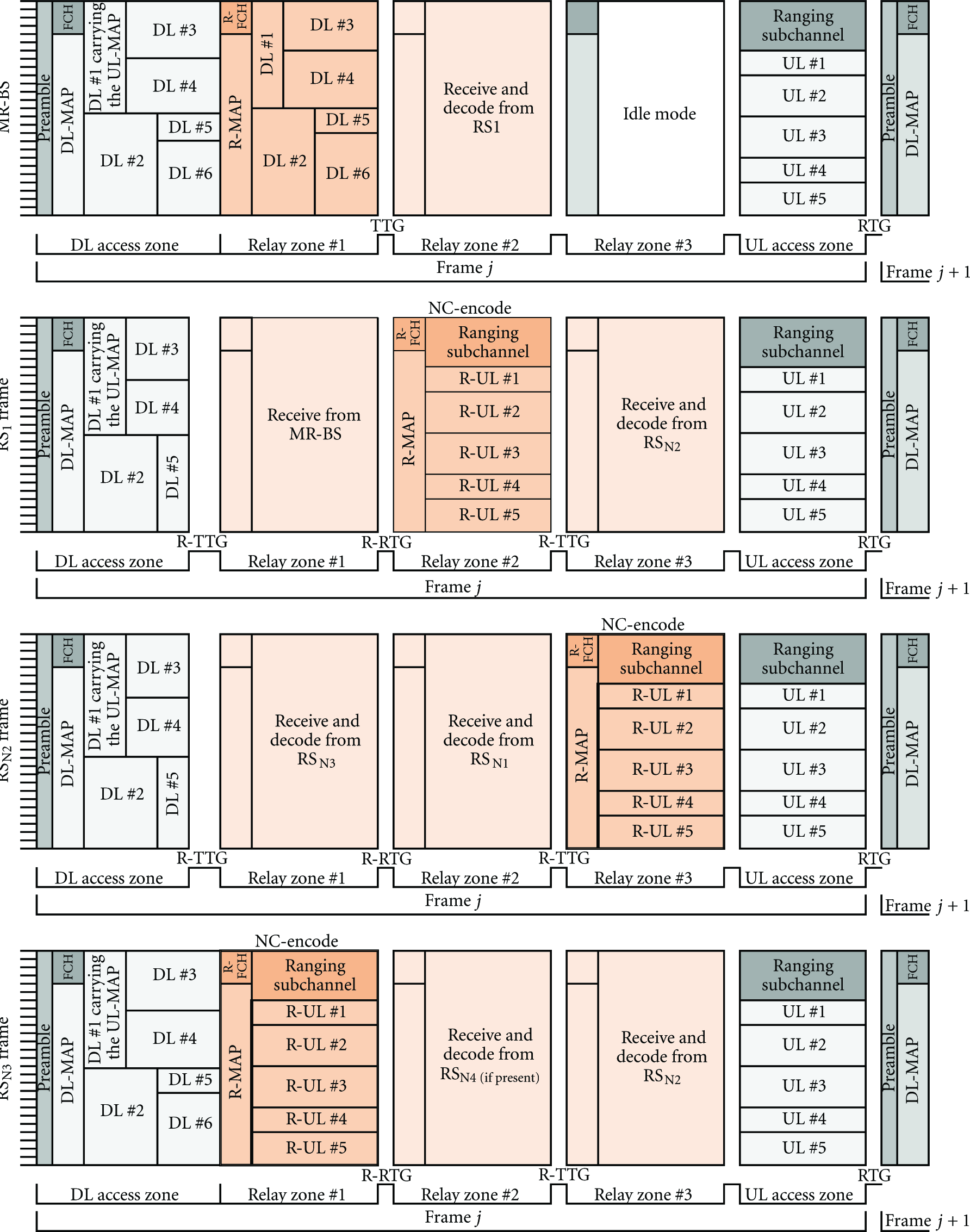
The IEEE 802.16j standard document describes two approaches of the multihop relay frame structure [2]: the repeating patterns of the multiframe and the more than one relay zone in the single frame structure. The proposed frame structure, NC-BR frame, is laid on the second one. Figure 5 shows the proposed NC-BR frame. The frame format at the MR-BS and the RS is divided into 3 different zones: the DL access zone, the UL access zone, and three relay zones. Both DL and UL access zones are used for communicating with the direct connected MSs of each MR-BS/RS, while three relay zones are used in the communication among the MR-BS, super-ordinate, and sub-ordinate RSs. Figure 6 shows the NC-BR transmission sequence in the frame structure.
NC-based relay frame structure design.

NC-BR transmission sequence in frame structure.

Detail of NC-BR operation.
One significant difference of this proposed frame structure and the original frame structure is that the number of zones in the MAC frame is independent on number of RSs hops. Therefore, the number of the relay zones of the NC-BR is strictly 3 in every situation. As a result, the throughput degradation and delay increase will be independent from the number of RSs hops.
Following is the example of the NC-BR frame structure and the relay zones capable to be the NC-based zones.
According to three relay zones of MR-BS from Figures 5 and 6, relay zone #1 is assigned to transmit data to RS1, relay zone #2 is assigned to receive and decode data from RS1 which is NC-BR enable, relay zone #3 is stay in idle mode. At RS1, relay zone #1 is assigned to receive data from MR-BS, the NC-BR enabled relay zone #2 assigned to encode and transmit data to MR-BS and RS2 in the same transmission, relay zone #3 is to receive and decode data from RS2 which is NC-BR enable. From RS2 and beyond, the NC-BR enable zone is placed at relay zone #3 then #1 then #2 and repeating; other two relay zones are assigned to receive and decode data from super-ordinate or sub-ordinate RSs. If it is no more sub-ordinate RS, the last RS in the chain will have idle mode assigned to one relay zone. Noticeably, no more than two transmission opportunities in relay zones of the overall NC-BR system are left to waste in idle mode. This is another reason, beside the throughput improvement from network coding, that our approach can provide substantial improvement from high utilization of our new frame structure design. Hence, by applying proposed NC-BR, network coding will also help RSs transmit more data in relay link results are to relief both optimal offered load point and bottle-neck point.
Figure 6 also presents the transmission sequence within relay zone. Each zone in the transmission sequence can be in either transmission, receive, or idle mode. The transmission sequence of MR-BS is assigned to transmission mode in relay zone #1, the receive mode in the relay zone #2, and idle mode in relay zone #3. The transmission sequence of RS1 is assigned to receiving data from the MR-BS on the relay zone #1. The NC-based zone can be applied to the relay zone #2, which encodes and transmits data to both directions (MR-BS and RS2) in a single transmission. The relay zone #3 is to receive and decode an encoded data from RS2. The relay zone of center node RS that is in the transmission mode is defined as the NC-based zones. The NC-based zone in each RS transmission sequence is denoted by

It is worth noticing that the number of relay zones in the NC-BR frame is independent on the number of RS hops. However, in the original relay scheme, the idle mode has to be assigned to more zones in the transmission sequence to avoid the transmission interference when the number of RS hops is increased. The idle mode is considered as waste.
4.4. Scope Discussion
In this part, we would like to discuss on scope and limitation of NC-BR. Figure 8(a) shows Variables present and Figure 8(b) shows Traffics present of multihop relay wireless network in scope of this paper. The present design is focus to implement on the relay station of IEEE 802.16j multihop networks. More generally, NC-BR can be used in any multihop relay wireless networks that satisfy the following.

(a) Variables present. (b) Traffics present.
(1) Available coding opportunities for relay station, which need 3 or more hops in chain topology for coding opportunities of a relay in the middle.
(2) Buffer: NC-BR requires small buffer space to keeps the recently transmit data for further decode of new coming receive.
(3) Omnidirectional antenna: the wireless backhaul of relay station that transmit to super-ordinate RS/BS and sub-ordinate RS has to transmit to both direction at the same time. More generally, the wireless backhaul should use the omnidirectional antenna or other kinds that transmit to both direction.
(4) Higher gain in balance uplink-downlink traffic ratio: there have been studies about XOR network coding in wireless network [12]; the balance ratio of uplink to downlink traffic is the highest throughput gain scenario. In our studies following the same trend, the balance ratio of uplink to downlink traffic is the best scenario. As we have more opportunities to apply XOR network coding to uplink with downlink data in each frame, then transmitting together in single transmission, consequently highest throughput gains can be obtained. On the other hand, when the uplink and downlink traffic is not equal, the opportunities to apply XOR network coding will be decreased, and also the throughput gain.
5. Performance Analysis
In this section, an analytical model to study the throughput degradation and delay increase in IEEE 802.16j multihop relay network is described.
Assumptions.
All MR-BS and RS are operated in the same frequency channel, the same transmission power, the same range. Moreover, all wireless relay links use highest modulation. Thus, models to study the throughput degradation and delay increasing in the IEEE 802.16j multihop relay network are studied in this paper.
For simplicity, all MR-BS and RSs are assumed to operate in the same transmission power and ranges. Highest modulation is used on all wireless backhaul links. The coverage and interference ranges of each RS can cover super-ordinate RS/MR-BS, sub-ordinate RSs and MSs of the RS. Table 1 shows notations used for performance analysis.
Notations used.

The rest of this section is organized as follows. In Section 5.1, the analytical model of relay link efficiency limit is described that has effect to the performance of both original relay and NC-BR. In Section 5.2, the throughput analysis model and providing the comparison between both approaches are described. In Section 5.3, the end-to-end delay analysis model and comparison of both approaches are described.
5.1. Relay Zone Efficiency
Due to the NC-BR having higher utilization in the relay zone, it results in higher RE than the original relay. Figure 9 shows an RE of 5-hop scenarios of the original relay and the NC-BR scheme that are 1/8 and 1/3, respectively. The RE of the original relay scheme can be expressed by


Traffic handled by the relay zone efficiency (RE).
The REs of 3-hop and 4-hop scenarios of the original relay scheme are 1/4 and 1/6, correspondingly. On one hand, when more RS hops are added to the scenario, the RE will decrease in the case of the original relay scheme. On the other hand, the RE for NC-BR is always 1/3 and independent from the number of RS hops.
5.2. Throughput Analysis
The fair comparison between the NC-BR and the original relay scheme started by making the equal size for the following parameters: 
According to (4), the term
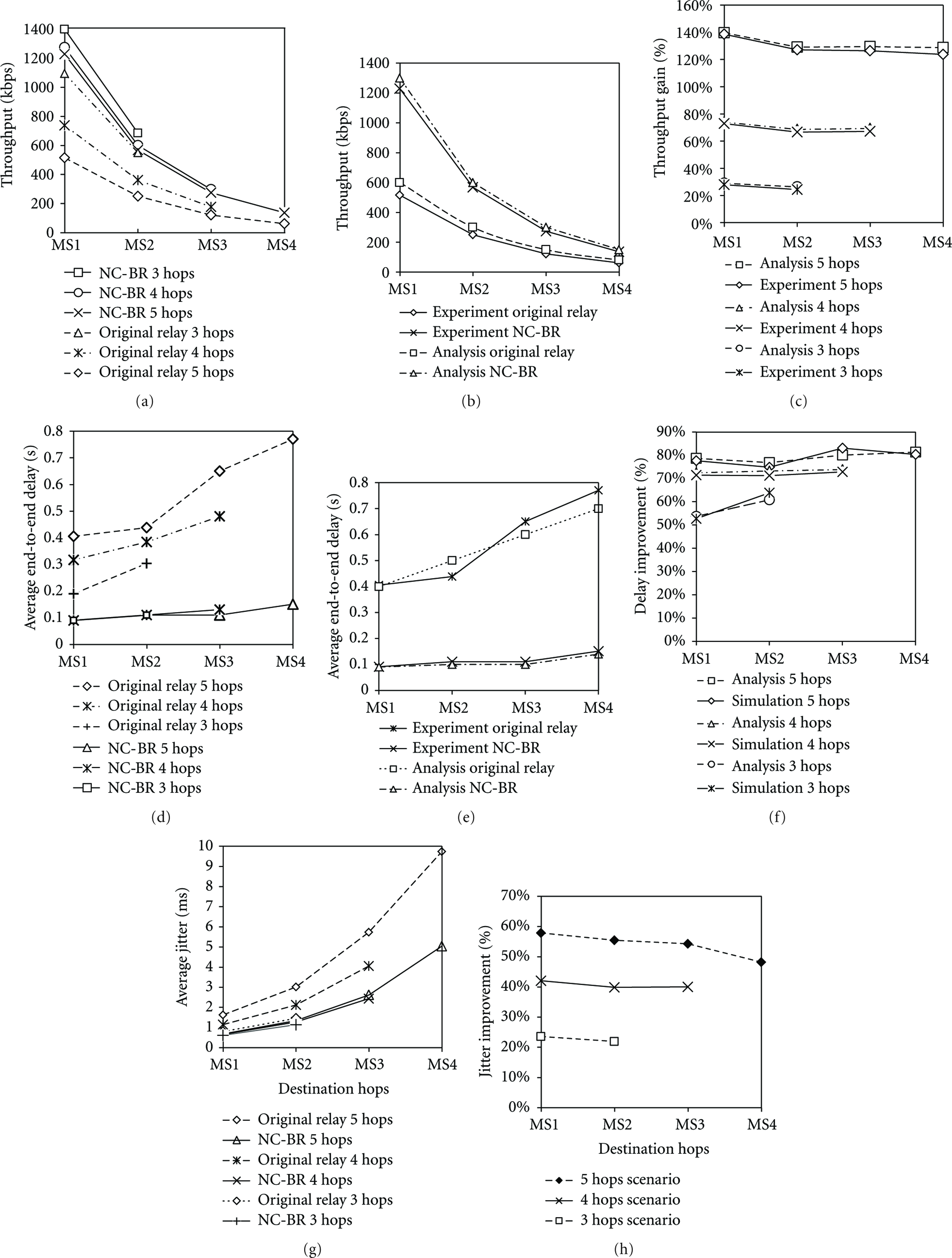
(a) Throughput of original and NC-BR, 3–5 hops scenario. (b) Throughput of original and NC-BR compare to analysis result, 5 hops scenario. (c) Throughput gain %, 3–5 hops scenario. (d) Average end-to-end delay of original and NC-relay, 3–5 hops scenario. (e) Average end-to-end delay of original and NC-BR compare to analysis result, 5 hops scenario. (f) Delay improvement %, 3–5 hops scenario. (g) Average jitter of original and NC-BR, 3–5 hops scenario. (h) Jitter improvement %, 3–5 hops scenario.
5.3. End-to-End Delay Analysis
The proposed NC-BR and the frame structure can reduce the end-to-end delay. By reordering the transmission sequence of RSs, they allow traffic flow to travel up to 3 RS hops in the single MAC frame. The result shows that they reduce the delay in case of the multihop flow by up to 3 MAC frames duration. Hence, the value of 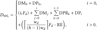
Referring to (5), the delay from the multihop frame structure is given by
6. Experimental Result
In order to prove the efficiency of the proposed NC-BR mechanism and the frame structure, QualNet 4.5 was extended to support the multihop relay function. The simulation results to demonstrate the performance of the proposed scheme are elaborated as follows.
6.1. Simulation Model
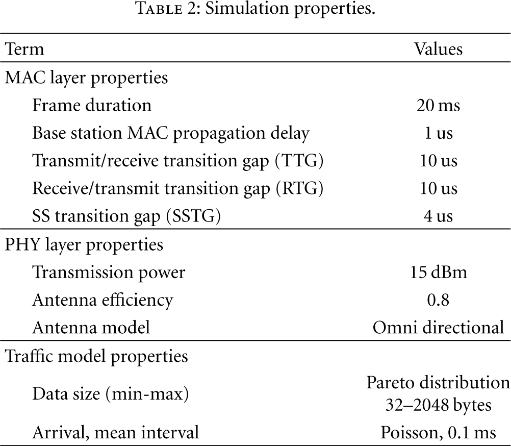
In order to represent a realistic IEEE 802.16j multihop relay network, the simulation model has six scenarios which are 3-hop, 4-hop, and 5-hop scenarios, with and without the NC-BR scheme. Each MR-BS/RS covers 20 MSs. Each MS communicates to the MR-BS with the similar traffic. Figure 9 shows an example of 5-hop scenario configuration. The following parameters are used in the simulation: 300 s of traffic flows generated, 64QAM modulation, 20 ms for frame duration, 10 μs for TTG/RTG, 4 μs for SSTG, 32–2048 bytes for data size with Pareto distribution, and the arrival time interval with 0.1 ms mean in the Poisson distribution. The simulation properties are shown in Table 2.
Simulation properties.
6.2. Simulation Results
According to the experimental results in Figure 10, the throughput was measured in Figures 10(a), 10(b), and 10(c). Figure 10(a) shows comparisons between throughputs of 3–5 hops scenarios of the original relay against the NC-BR. The results show a significantly higher throughput of the NC-BR comparing with the original relay scheme. Figure 10(b) shows the comparison between the theoretical values from (4) against the simulation results of 5 hops scenario, based on the original relay and the NC-BR. The results show that the analysis results and the simulation results are closed to each other; thus, the accuracy of the theoretical model (4) is confirmed.
Additionally, Figure 10(c) shows the percentage of the throughput gained from the NC-BR, comparing with the original relay approach from the results shown in Figure 10(a). Referring to Figure 10(c), the throughput gain is 24–28% on 3 hops scenarios, 67–73% on 4 hops scenarios, and 124–140% on 5 hops scenarios.
Delay was measured and shown in Figure 10(d) to Figure 10(f). According to Figure 10(d), the comparison is between the average end-to-end delays of total six scenarios, 3–5 hops scenarios of the original relay comparing against the NC-BR. The results show that, in the case that the number of hops is equal, the NC-BR scenarios provide significantly lower end-to-end delay than the original relay scheme.
Figure 10(e) shows the comparison between the theoretical values calculated from the theoretical model (5) against the simulation results of 5 hops scenario, with the original relay and the NC-BR. The result shows that, on the NC-BR, there is a small difference between the analysis and the simulation results; this confirms the accuracy of the proposed theoretical model (5). Based on Figure 10(e), the difference between the simulation and theoretical values of the original relays is very clear because there is an unpredictable delay variation from the queue length and packet dropped at each hop during the simulation period.
As a consequent of the experiment, the jitter values are obtained. Figure 10(g) shows comparisons between 3–5 hops scenarios of the original relay against the NC-BR. Results show that, in the case that number of hops is equal, NC-BR scenarios provide much lower jitter than the original relay approach.
In order to obtain a clear picture of the performance improvement after applying the NC-BR, improvement metrics, the percentage of delay improvement, and percentage of jitter improvement, are used as the indicators as shown in Figures 10(f) and 10(h). According to Figure 10(f), the delay improvement is 53–64% on 3 hops scenarios, 71–73% on 4 hops scenarios, and 75–83% on 5 hops scenarios. Moreover, Figure 10(h) shows that the jitter improvement is 22–24% on 3 hops scenarios, 40–43% on 4 hops scenarios and 49–58% on 5 hops scenarios.
7. Discussion
As a consequence of WiMAX technology development, many service providers have deployed it as their new wireless broadband services. Moreover, the multihop relay network, IEEE 802.16j, enables multihop communication in IEEE 802.16e networks by enhancing the coverage, per user throughput and system capacity of IEEE 802.16e. Thus, using RSs can significantly reduce the deployment cost of the system.
Considering the frame structure of the IEEE 802.16j standard document [1], it supports two approaches, and both approaches cause limitation to the relay zone utilization, especially on over the 3 hops scenarios. Therefore, [4, 6, 7] proposed the frequency reuse mechanism on the existing frame structure as mentioned in [1] to relieve the problem of relay zone utilization limit. Unfortunately, as to the signal interferences limitation and the opportunity to apply the frequency reuse mechanism are very limited, obtained result of [4, 6, 7] is only slightly improved RE from 1/8 to 1/6, which is no more than 4%, for at least five or more hops scenario. Different from the previous mechanism, NC-BR allows RSs to combine multiple wireless transmissions into single transmission using network-coding technique. The result has shown that the relay zone utilization is significantly improved.
Based on the mechanism of [1], a frame structure has been designed to serve this mechanism. However, this structure causes serious problems of the wireless multihop networks as mentioned previously because of the signal interference avoidance constraint. Thus, whenever the number of RS hops increases, the number of the relay zones is automatically increased. For this reason, the utilization of the relay zone is critically degraded. This affects to the throughput and delay of the entire network.
According of the different mechanism of the proposed mechanism, NC-BR, its frame structure is modified to have just 3 relay zones which are independent from the number of RS hops. As a result, the relay zone utilization is maintained. So, the performance metrics of the entire network are improved from the original mechanism at least 24–140% for throughput gain and 53–83% for delay improvement.
8. Conclusion
Wireless technology is an important development in the communication area. People need to exchange their data from every corner of the world. However, implementing a basic communication system needs to implement several base stations (BSs) in order to cover a large communication area. In doing so, a high investment cost and the network complexity arises. As a consequence, the development of the IEEE 802.16j multihop relay network brings a significant change in the world because the number of BSs is replaced by RSs. Thus, the complexity of the entire network and the investment cost are reduced. In addition, the RSs enhance coverage and capacity to the MS. However, implementing multihop relay network in a large-scale WiMAX network has problems of the throughput degradation and the incremental of end-to-end delay when the number of hops is increased.
Therefore, in this paper, the foremost study in applying the network coding technique to WiMAX has been performed and evaluated. Thus, a network coding-based relay scheme, called NC-BR, and the corresponding frame structure are proposed. The proposed solution allows an RS to combine two sets of data in the wireless backhaul using the XOR operation and transmit it in a single transmission instead of two. Consequently, the throughput and the delay are improved. Additionally, the jitter is smaller. Thus, the transmission situation is obviously improved and suitable to serve several types of transmitted data.
Footnotes
Acknowledgment
This work was supported by the 90th Anniversary of Chulalongkorn University Fund (Ratchadaphiseksomphot Endowment Fund).