
Abstract
The effect of heat treatment and shot peening on the fatigue life of an aluminum aircraft wheel was studied. The effect of residual stress and heat treatment on the fatigue of specimens was studied by means of fatigue testing, residual stress measurement, and fractography. Finite element simulation was used for life assessment and evaluation of the effect of surface treatments on the life extension of the aircraft wheel. The results obtained show that the operational life of the aircraft wheel extended by imposed compressive residual stress and aging treatment.
1. Introduction
Safety and integrity are the primary demands in aircraft industry. However, life extension of critical parts is also considered mainly due to the increasing cost of aircraft parts. It is widely accepted that most of service failures in aircraft components are due to fatigue, and it rates to about 60% of the total failures [1]. Aircraft wheel is a critical part that is imposed by high stresses due to landing and takeoff. Two series of Al-Zn-Mg(-Cu) aluminum alloy, namely, AA2000 and AA7000, are mostly used in aircraft wheel industry.
Heat-treatable Al-Zn-Mg(-Cu) alloys are the strongest aluminum alloys that are commercially available [2]. It is interesting to note that in aluminum alloys grain boundary strengthening is not a significant mechanism to strengthen the material. This is mainly due to that the value of Hall-Petch constant for these alloys is almost ten times smaller than steels and titanium alloys [3]. Precipitation hardening is the major strengthening mechanism in Al-Zn-Mg(-Cu) alloys and is consisted of the formation of a series of fine precipitates from a supersaturated solid solution that act as obstacles to moving dislocations [4, 5]. It is worth noting that the mechanical properties of aluminum wheels are degraded due to the coarsening of these precipitates. Reheat treatment of the used aircraft wheel is a solution to life extension of these parts [6].
Residual tensile stresses affect the fatigue life of components under cyclic loading. Thus, the presence of compressive residual stress near the surface is believed to enhance the fatigue life. A hard and compressively stressed surface layer which inhibits crack propagation can be achieved with shot-peening [7, 8]. The dislocation density and surface hardness are also increased by shot peening [9].
Failure of aircraft wheels is studied by a number of investigations. The influence of various factors on the fatigue of aircraft wheels was considered by Agamirov et al. [10]. Bhaumik et al. [1] studied the premature failure of the wheel hubs. They found that fatigue crack originated at the stress concentration site results from corrosion. Kosec et al. [11] observed numerous pits on the rim surface where the crack propagated over them. They concluded that pits served as stress concentrators on the rim surface and initiated the fatigue crack.
The objective of the present study is to increase the life of an AA7050 aluminum aircraft wheel by a suitable combination of heat treatment and shot-peening. The fatigue life of the wheel was predicted based on the experimental data and finite element simulation.
2. Experimental Procedures
The 35 kg aircraft wheel was made of AA7050, the chemical composition of which is listed in Table 1. A cylindrical sample that is 40 mm long and 15 mm in diameter was machined out of the wheel in radial direction and subjected to different heat and surface treatments as is shown in Table 2. The heat treatment procedures consisted of a conventional 120°C aging treatment (conditions B, C, and F) and a double-aging treatment (condition E) to increase the strength of the alloy. The shot peening was performed by 0.84 mm steel shots at an ALMEN intensity of 0.015 mm.
Chemical composition of AA7050 in wt%.

Different heat treatments and shot-peening performed on test specimens.

The specimens used in the rotating bending fatigue tests had a diameter of 9 mm and a length of 35 mm. The machined surfaces of the gage section of the test specimens were ground through 800-grit silicon carbide paper and then mechanically polished to remove any and all circumferential scratches and surface machine marks. Fatigue testing was performed in a rotating bending fatigue machine, HSM-14.
The samples for microstructural examinations were mechanically polished according to the standard procedure and then etched with a solution of 10 mL Hf, 5 mL HNO3, and 85 mL H2O. Field emission scanning electron microscopy was carried out on a HitachiS-4160 with an accelerating voltage of 35 kV.
3. Results and Discussion
3.1. Fatigue Behavior
The S-N diagrams for different samples are shown in Figure 1. It is clear that the fatigue life of samples increased by the applied heat treatment, excluding sample F. However, the fatigue life of sample C is longer than sample B. Considering that the heat treatment for both samples is similar, the enhanced fatigue life can be as a result of the shot peening process. Furthermore, the effect of peening on the fatigue life in the high cycle fatigue region (i.e., low cyclic stress) is greater than the low cycle fatigue region (i.e., high cyclic stress). This is due to that high local monotonic or cyclic strain regardless of its sign tends to reduce, or even annihilate, the residual stresses [12–14].

S-N diagrams for different samples.
The heat treatment of sample F is the same as sample C, but its fatigue life is degraded. This is due to the residual compressive stresses released following the heat treatment as it is shown in Figure 2. In contrast to sample F, high compressive residual stress of about 300–400 MPa is obtained in all regions 0–200 μm from the surface of samples C and E.

Variation of compressive residual stress with distance from surface for different samples.
3.2. Fatigue Fracture Surface
Figure 3 shows the micrograph of the specimens fatigued till final fracture. Fractographic observations show that specimens failed by a ductile fracture with a high density of microdimples in the aluminum matrix phase. The fracture morphology remained similar for all the samples except for the density of microdimples, which was found to be higher at higher strain amplitudes.
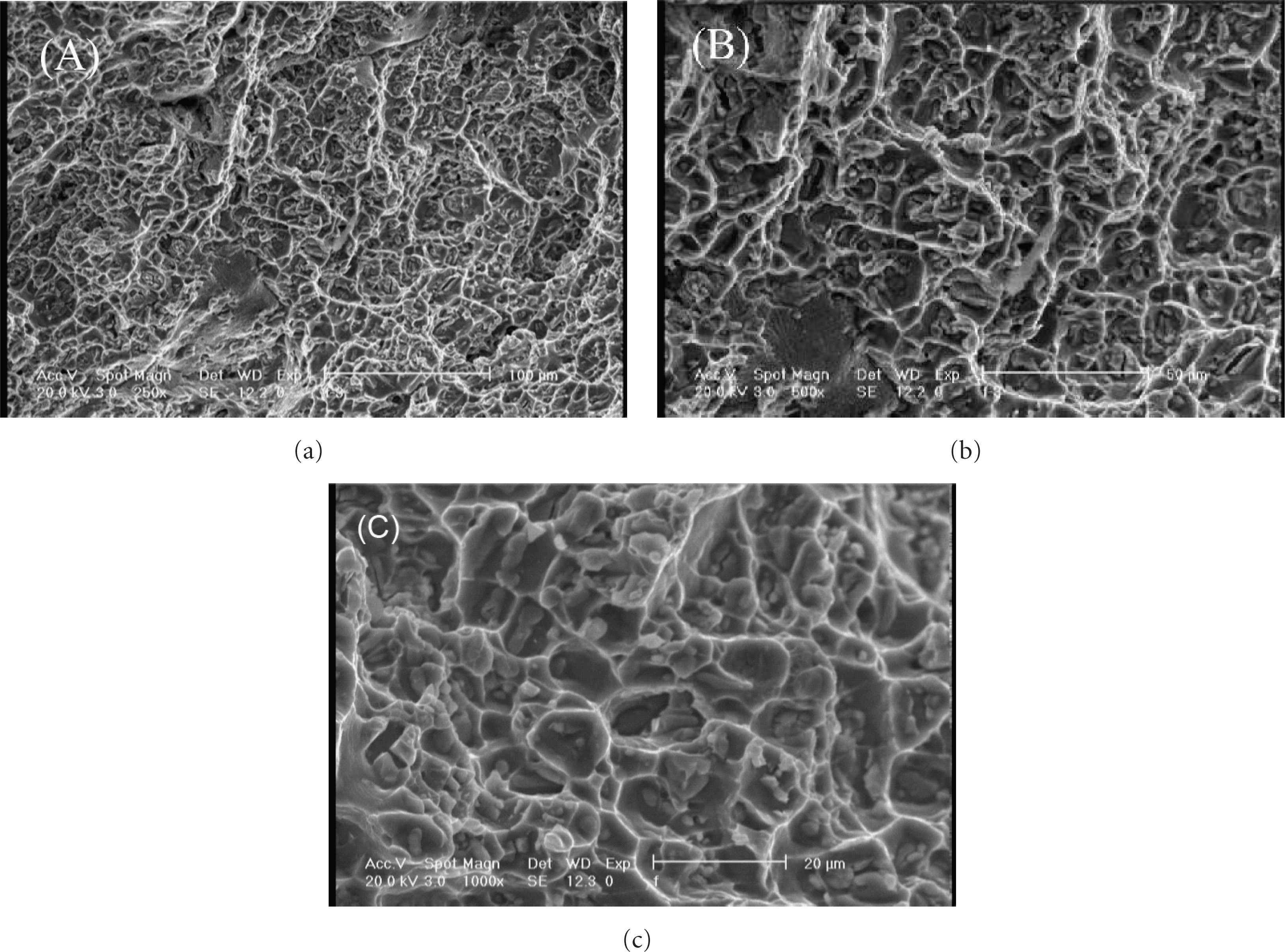
Fracture surface of different samples (a, b and c) following fatigue fracture.
Important microstructural features that significantly affect the fatigue properties of heat-treatable aluminum alloys are as follows: (i) large precipitates and dispersoids, (ii) fine and strengthening precipitates, and (iii) dislocation networks and dislocation interactions [15]. Considering Figure 3, there are secondary phase particles distributing at the bottom of the dimples.
Their importance in nucleating fatigue cracks relates to the following three factors: (i) a hard dispersoid can act as a stress concentrator, thereby localizing deformation in much the same way as a notch, (ii) debonding may occur along the dispersoid/matrix interface, and (iii) the relative brittleness of intermetallic compounds allows the possibility of precracking [16]. The observations reported here are also consistent with other researches which report that the presence of dispersoids plays a dominant role in fatigue crack nucleation in aluminum alloys [16–18].
3.3. Finite Element Simulation
The FEM software MSC Fatigue was used to simulate the fatigue behavior of the aircraft wheel. The aircraft wheel was modeled in 3D with 99400 nodes and 80960 elements. The fulcrum is the inner part of the wheel, shown in Figure 4. The takeoff and landing loads and velocities were estimated on the basis of the official documents as listed in Table 3.
Aircraft wheel loading conditions and velocities.


Fulcrum position in aircraft wheel model.
Figure 5 shows the distribution of von-Mises stress in the aircraft wheel during takeoff. The boundary conditions assumed are as following. The center of the wheel where the load is applied is assumed to be stationary. The loading was based on the aircraft wheel loading conditions and velocities (Table 3) and fulcrum position (Figure 4). Taking into account that the landing and takeoff loading are similar, the von-Mises stress during landing can be calculated on the basis of the following relation:

Considering the stress distribution and the S-N diagrams (Figure 1) the fatigue damage in the aircraft wheel during each working cycle (one full rotation) was calculated and is shown in Figure 6. The calculated fatigue damage can be converted to fatigue life as follows:

where N is fatigue life, and D is fatigue damage during each cycle. On the other hand, N is the number of cycles to failure and D is a fraction. The specimen will be failed when D is equal to one. Considering both the takeoff and landing cycles, the life of the aircraft wheel can be estimated on the basis of Miner's rule

where x is the number of takeoff or landing. The NTakeoff or NLanding can be calculated based on (2) and the calculated fatigue damage during each cycle (Figure 6). It is worth noting that the total number of full rotations can be estimated by considering the flight band length and the wheel perimeter.

Distribution of von-Mises stress in the aircraft wheel during takeoff.

Calculated fatigue damage in the aircraft wheel following one full rotation.
Assessment of the allowable flight number for the aircraft wheel is an essential demand. However, the flight numbers for different wheel conditions cannot be directly derived from fatigue test results. Consequently, numerical simulation was conducted to calculate the allowable flight number. Figure 7 shows the calculated allowable flight number for different wheel conditions. It is clear that the wheel life is extremely increased following the heat treatment and peening imposed in C and E conditions. However, the life of aircraft wheel increased by a factor of 1.3 following simple heat treatment (sample B) while it is increased by a factor of 15 following heat treatment plus shot peening (sample C). Consequently, shot peening is much more effective than simple heat treatment. It is worth noting that sample F has the shortest lifetime. This is mainly due to the imposed residual compressive stresses released following the heat treatment (Figure 2), and consequently the fatigue life of the sample was drastically reduced. Furthermore, the imposed surface treatment increased the surface inhomogeneity that reduced the fatigue life of the sample.
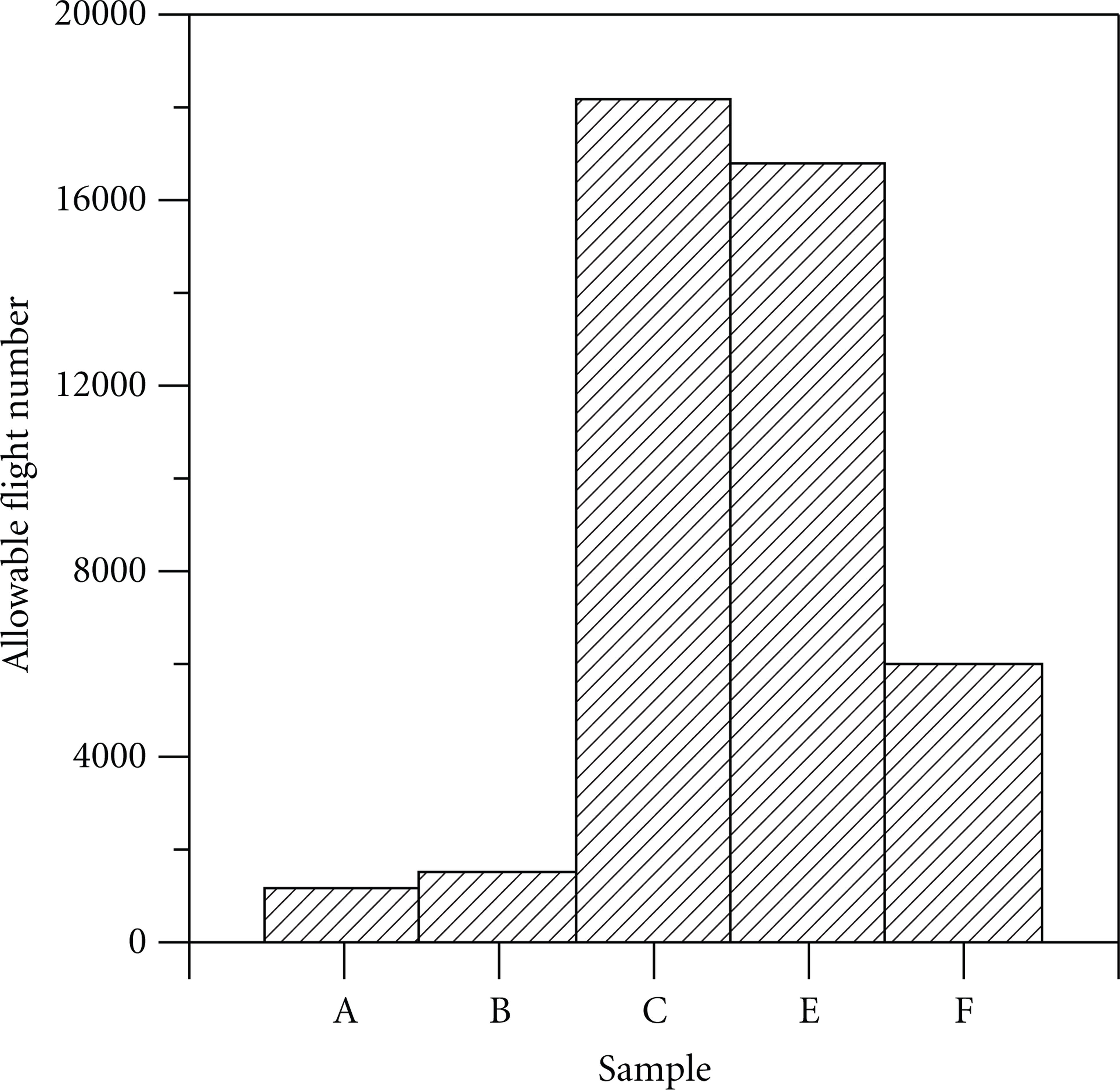
Calculated allowable flight number for different wheel conditions.
4. Conclusions
Considering finite element simulation and results of fatigue testing, the effects of shot peening and different heat treatments on the life extension of an AA7050 aircraft wheel were investigated. The following conclusions can be drawn from the analysis.
A simple methodology was introduced for life assessment of aircraft wheels based on flight data and finite element simulation.
Both the heat treatment and shot peening increases the operational life of the aircraft wheel. However, the peening process was more effective. The sequence of heat treatment and peening is very essential to life extension. The best results are obtained when heat treatment is preceded to peening process.
The imposed compressive residual stress of about 300–400 MPa in all regions 0–200 μm from the surface of samples results in 14 times life extension of the aircraft wheel.