
Abstract
The focus of this paper is to give a better understanding of beat phenomenon in the free vibration test of a concrete beam with piezoelectric ceramic sensors from the view of mathematics. The cause of beat phenomenon from piezoelectric ceramic sensors embedded in the concrete beam is illustrated and the influence factors of beat phenomenon are discussed. The results show that the beat phenomenon from piezoelectric ceramic sensors in the concrete beam is caused by the coupled responses with similar model frequencies in different directions. The influence factors of beat phenomenon due to damping effect, impact direction, sensor position and sectional dimension are discussed. As the damping ratios increased, the amplitude of beat signal will die out in an exponential decay. Meanwhile, the damping has a tiny influence on the beat frequency of system response, the amplitudes of beat signal both in the time and frequency domain are changed with the variation of impact direction. In addition, the amplitude of beat signal will be also changed with the position of sensors altered. The beat frequency will get more with the greater difference of sectional dimension.
1. Introduction
Piezoelectric materials have a broadly applicative prospect in structure health monitoring due to their characters of electromechanical coupling, simple structure, low cost, good reliability, and wide frequency response range. The piezoelectric transducers based on positive and negative piezoelectric effect have been applied as actuator and dynamic measurement in damage identification [1–3], impact force location [4, 5], and fatigue crack detection [6, 7] in composite structures. Besides, the piezoelectric transducers have been successfully utilized in civil engineering structures. Song et al. [8] have developed an overheight collision detection and evaluation system for concrete bridge girders using piezoelectric transducers. Li et al. [9] applied a new type of cement-based piezoelectric sensor to monitor the traffic flows and concluded that there is a good potential for the cement-based piezoelectric sensor in the engineering application for monitoring traffic flows in the field of transportation. Gu et al. [10] provided a method of piezoelectric-based strength monitoring, in which an innovative experimental approach is proposed to conduct the concrete strength monitoring at early ages. Song et al. [11] exploited smart aggregate (SA), an innovative multifunctional transducer, fabricated by embedding a wired, waterproof piezoelectric ceramic patch into a small concrete block. The proposed SA has been successfully utilized in the structural health monitoring of a full-size bridge girder [12], reinforced concrete shear walls [13], a two-story reinforced concrete frame subjected to progressive collapse [14], circular RC columns under cyclic combined loading [15], and circular reinforced concrete columns after seismic excitations [16].
The free vibration of undercritically damped system would be decayed exponentially, as shown in Figure 1 [17]. However, when conducting the free vibration test with piezoelectric ceramic sensors, instead of an exponential decay, the vibration tends to decrease or increase periodically as shown in Figure 2, which is characterized as the classical beat phenomenon. It will be difficult to evaluate the frequency or damage of structures from the beat signals. However, there is no definite conclusion about the cause and influence factors of beat phenomenon in piezoelectric transducers currently. In this paper, the cause of beat phenomenon in piezoelectric ceramic sensors of a simply supported beam is illustrated from the view of mathematics. In addition, the influence factors of beat phenomenon due to damping effect, impact direction, sensor position, and sectional dimension are discussed.
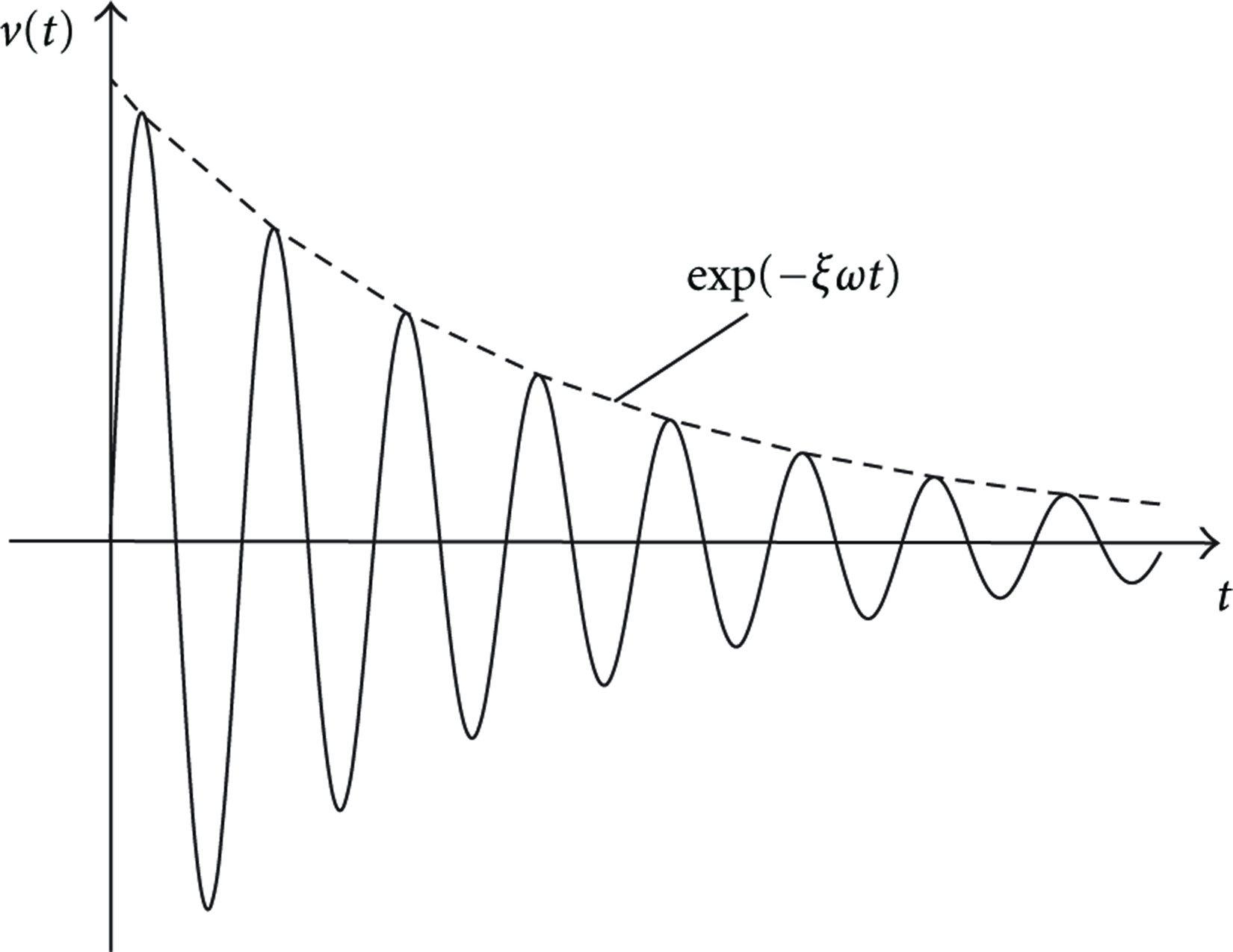
Free-vibration response of undercritically damped system.

The classical beat phenomenon from piezoelectric ceramic sensors.
2. The Analysis of Beat Phenomenon from Piezoelectric Ceramic Sensor Embedded in the Simply Supported Beam
A simply supported beam embedded with piezoelectric ceramic sensors is taken as an example to analyze the cause of beat phenomenon. The hypothesis is put up that the calculative model is the ideal simply supported beam, and the material of structure is in elastic phase. The size of the beam is

The calculative model of the simply supported beam.
2.1. The Stress Condition on the Surface of Sensor Dipole
The electrode surface of piezoelectric ceramic sensor has only axial stress when subjected to the curvature movement. The initial velocity can be resolved into orthometric components


Substituting (8) into (7), then the value a is acquired by the vibration


The initial condition 1st mode is calculated as (11) based on the mode shape orthogonality:


2.2. The Output Voltage of Piezoelectric Ceramic Sensor
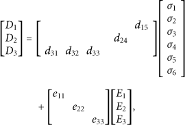
By means of the piezoelectric sensors and signal acquisition system, the changes of stress are transformed into voltage signal. Following assumptions are made to the computational model of piezoelectric ceramic sensors to facilitate the analysis according to the actual background and the need of the analysis. First, the piezoelectric ceramic can be considered as the ideal elastic material without free charge. In addition, the electrode is isopotential, which means that the electric field between both electrodes is uniform, and there is no electric field in any other directions. The piezoelectric equation can be formulated as (15) [18]:


The positive direction of computation model.
When the poling of sensor is in 3-direction, the eternal electric field is zero, and (16) is expressed by

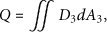
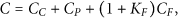
Piezoelectric ceramic has very high impedance, in which the output current is weak. The output signal needs to be collected through charge amplifier which can provide low impedance to signal. Figure 5 is the operating principle of charge amplifier, where

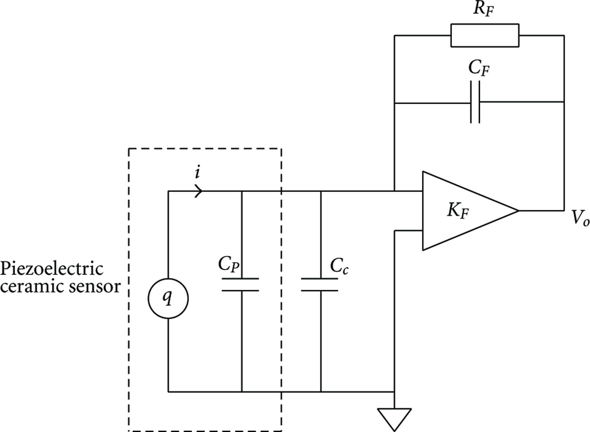
The operating principle of charge amplifier.
For typical piezoelectric sheet, the axial thickness is so thin that the shear stress in 1 and 2 directions can be neglected. Substituting (18) and (19) into (21) leads to

The sensitivity of piezoelectric ceramic sensor can be defined as (23), which represents the relation between output voltage and stress on the surface of electrode, and V can be depicted as (24):


Illustration of the beat phenomenon with equal
To give a general understanding of beat phenomenon, one can consider the solution of system response by the way of rotate vector method. As shown in Figure 7,


Illustration of V by rotation vector method.

Anatomy of the beat phenomenon with unequal
From previous discussion, the beat frequency
3. The Influence Factor of Beat Phenomenon
In this section, the influences of beat phenomenon including damping effect, impact direction, the position of sensor and anisotropic properties are discussed. Unless mentioned otherwise, the damping ratio of calculative model is 0.01 in both orthometric directions, and other parameters are listed in Table 1.
The parameters of the simply supported beam.

3.1. Damping Effect
Figure 9 shows the upper envelope of output signal with equal
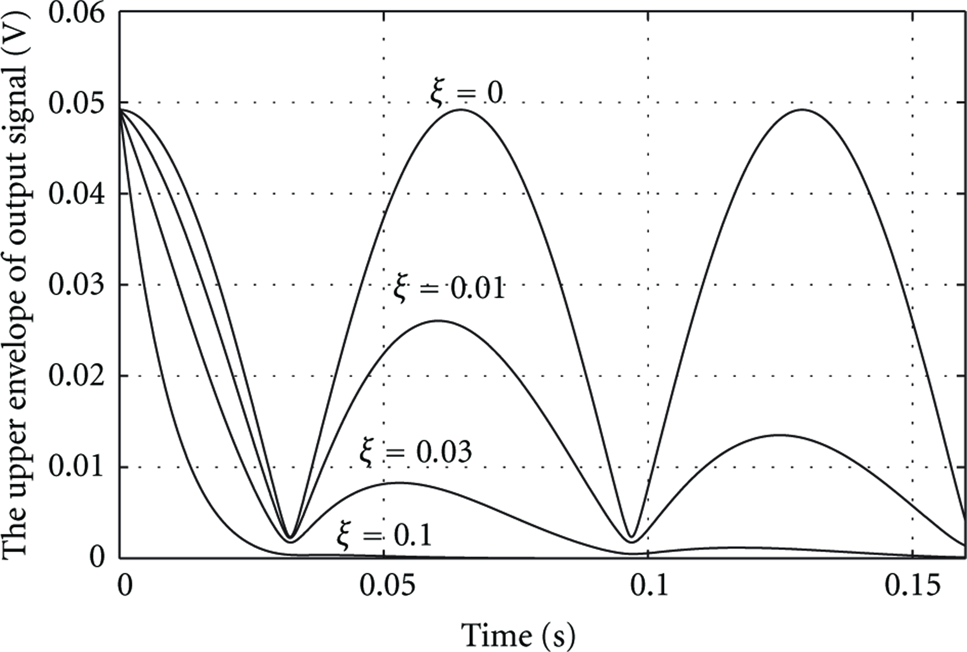
The upper envelope of output signal with equal

The upper envelope of output signal with unequal
The damping not only leads to the attenuation of amplitude but also reacts on the beat frequency. Figure 11 depicts the change of beat frequency in which

The change of beat frequency with different
3.2. Impact Direction
With the variation of impact direction, the initial conditions in orthorhombic modes would be different, and the amplitude of coupled response of sensor and the magnitudes in each modal frequency are also changed. Figure 12 is the time history and frequency domain chart of output signals with the impact direction of 0°, 45°, 60°, and 90°. From the figures of time history, the beat phenomenon is observed obviously with the eccentric impact force. If the impact direction is parallel to the symmetric axis of the section, beat phenomenon would not happen. Also, from the figures of frequency domain, it is difficult to evaluate the structural frequency if beat phenomenon happened.

The time history and frequency domain chart of output signals.
Inversely, the maximum and minimum of the upper envelope expressed as 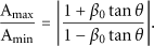
3.3. The Sensor Position
The stress on the surface of sensor dipole rather than the system frequency will be changed with the alteration of sensor position. Therefore, the position of piezoelectric ceramic sensor has no influence on beat frequency but has influence on the amplitude of sensor response. Figure 13 represents the upper envelope of beat signal with various

The upper envelope of beat signal with different

The
Figure 15 is the upper envelope of beat signal with different

The upper envelope of beat signal with different

The
3.4. Sectional Dimension
Sectional dimension can be regarded as a significant factor accounting for the beat phenomenon, for the natural frequencies in orthogonal directions of the beam are related to material properties. Figure 17 is the beat frequency in which the

The beat frequency with different

The upper envelope of output signal with different sectional dimension.
4. Conclusion
The beat phenomenon in the free vibration test of a simply supported beam is analyzed from the view of mathematics. The results show that the beat phenomenon of piezoelectric ceramic sensors is caused by coupled response with similar frequency in different directions. As the damping ratios increase, the amplitude of beat phenomenon will die out in an exponential decay. However, the damping effect has a tiny influence on beat frequency. With the variation of impact direction, the proportion of response in each single mode will be changed. Hence, the amplitude of coupled response of sensor and the magnitude in frequency domain are changed. The amplitude of system response can also be changed with the variation of sensor position in axial direction, which has no influence on the proportion of response in single mode. The location shift of sensors in the same section will change not only the coupled response but also the proportion of amplitude in both single modes. The sectional dimension is a vital factor for the beat frequency, which will get more with the greater difference of sectional dimension.
Footnotes
Acknowledgments
The authors are grateful for the support from Science Fund for Creative Research Groups of the National Natural Science Foundation of China (Grant no. 51121005).