
Abstract
Heat and mass transfer, which occur in the evaporation of a falling film of water, are studied experimentally. This evaporation allows the dissipation of the heat flux produced by twelve resistors, which simulate electrical components on the back side of an aluminium plate. On the front side of the plate, a falling film of water flows by the action of gravity. An inverse heat conduction model, associated with a spatial regularisation, was developed and produces the local heat fluxes on the plate using the measured temperatures. The efficiency of this evaporative process has been studied with respect to several parameters: imposed heat flux, inlet mass flow rate, and geometry. A comparison of the latent and sensible fluxes used to dissipate the imposed heat flux was studied in the case of a plexiglass sheet in front of the falling film at different distances from the aluminium plate.
1. Introduction
Currently, in rail applications secondary electronic components that are used in air conditioners or electric lighting are cooled using forced convection on the tops of the rail cars. Fans used for cooling these electronic components are very large, noisy, and require significant amounts of energy. To decrease the congestion, the noise, and the energy required for the fans, thereby making them cleaner and more efficient, one can consider installing the electrical components on a vertical plate inside the train (Figure 1(a)) that is cooled by natural convection or with a falling water film on the other side of the plate. The main purpose of this study is to examine the performance of the falling water film over the aluminium plate for different levels of heat flux and varying aluminium plate-to-Plexiglas wall distances.
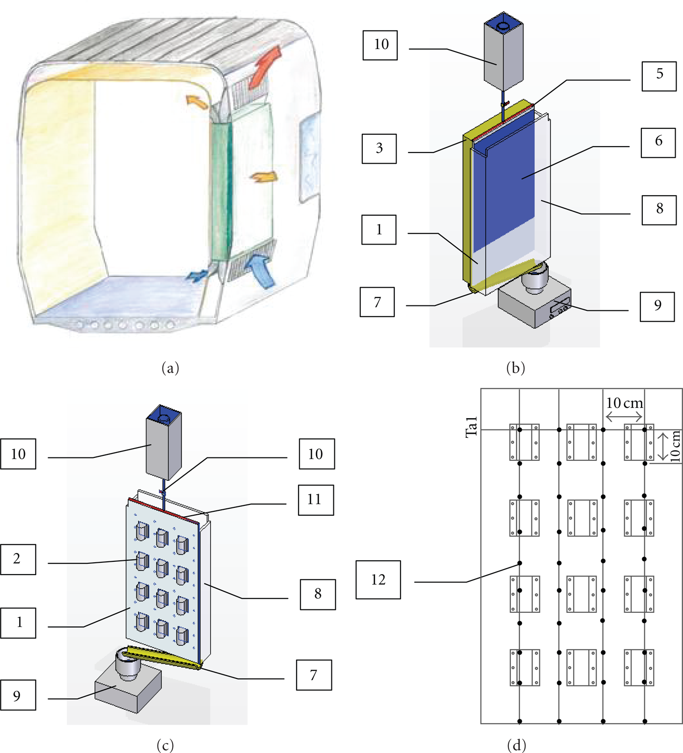
Experimental setup: (a) position of the vertical plate on the railway car, (b) front side of the model, (c) back side of the model without insulating layer, and (d) thermocouple locations on the plate. (1) Aluminium plate, (2) heating unit, (3) insulating layer, (4) liquid reservoir, (5) liquid distributor, (6) liquid film, (7) liquid collector, (8) plexiglass wall, (9) electronic balance, (10) valves, (11) fabric, and (12) thermocouple position.
Falling liquid film evaporators have always been used for heat transfer enhancement through latent energy transport. The main applications of liquid film vaporisation are desalination, refrigeration, and air conditioning. Evaporative cooling is also often encountered in the cooling of microelectronic equipment and the protection of system components from high temperatures in supersonic flying vehicles, in combustion chambers, in cooling towers, and in many other applications.
The advantages of falling film evaporators drive the research into the design and the operating strategy for falling film evaporators. However, the falling film evaporation process involves two-phase flow and heat transfer, and both evaporation and boiling can occur in the liquid film. As a result, the falling film evaporation process is complicated. Presently, the falling film evaporator industry still faces the challenges of optimising the design methods and the operating strategies.
The purpose of this study is to investigate the cooling of electrical converters used in the railway industry. For the cooling of electrical components, convective heat transfer or phase change are often used and are implemented through the use of devices such as heat pipes or flat heat pipe cooling [1, 2]. In this work, we investigate the cooling of electrical components by falling film evaporation and by natural convection.
Chun and Seban [3] and Seban and Faghri [4] experimentally and theoretically investigated the evaporation of a liquid water film into a pure water vapour. In their theoretical studies, they focused on the transport processes in the liquid film. In view of the complexity of the coupling between the momentum, the heat and mass transfer in the gas flow, and the liquid film through their common interface, other early studies primarily focused their attention on the heat and mass transfer in the air stream assuming the liquid film to be extremely thin. Under this assumption, transport in the film can be replaced by the appropriate boundary conditions for the gas flow. Cherif et al. [5] and Fahem et al. [6] investigated experimentally the effect of film evaporation on mixed convective heat and mass transfer in a vertical, rectangular channel. Two parallel channel walls were wetted by a water film and heated by a constant heat flux, while the other walls were dry and thermally insulated. The liquid film temperature, the evaporated flow rate, the upward airflow temperature, and the humidity were measured. Wide ranges of inlet airflow velocity, heat flux, and liquid film flow rate were considered. The experimental results showed that evaporation takes place on the majority of the surface of the two walls, and in some cases, evaporative cooling occurred, especially for small heating fluxes and large air velocities.
The study of Orfi et al. [7] concerned the experimental analysis of heat and mass transfer in a distillation cell. This cell is a parallelepiped of large form factor whose active walls are vertical. The cell is fed with salt water, and pure water is evaporated from a thin film that falls down a heated wall, while the opposite wall is maintained at a lower temperature and is used as a condensing surface. The experimental results showed that the heat transfer in the distillation cell is dominated by the latent heat transfer associated with evaporation. In addition, a parametric study of the behaviour of the distillation cell was performed. The authors suggested a convenient choice of the operating parameters to optimise the distillation yield.
An analysis of the buoyancy-induced heat and mass transfer over flat plates with different inclinations and inside a circular pipe was carried out by Gill et al. [8], Chen and Yuh [9], and Chang et al. [10]. Chandra and William Savery [11, 12] studied an upward forced airflow over a free-falling isopropyl alcohol film by the integral method. In their theoretical work, the measured temperature and concentration distributions over the gas/liquid interface were used to specify the nonhomogeneous boundary conditions required for solving the energy and species diffusion equations for the air-vapour flow. Laminar and turbulent forced-convection boundary layer flows of a gas over an evaporating liquid film on a flat plate were numerically investigated by Schroeppel and Thiele [13] with the same assumption. Similar studies were conducted by Chow and Chung [14, 15] for laminar and turbulent flows of air of various humidities and superheated stream over a liquid water film. The evaporation rates of water were measured by Haji and Chow [16], and the measured data agreed with the predicted values [15] if the heat loss from the water pan was accounted for. Analyses including transport processes in the gas flow and the liquid film were conducted for turbulent gas flows over a concurrent liquid flow by Shembharkar and Pai [17] and Baumann and Thiele [18]. However, in these studies the temperature distributions across the film were assumed to be linear.
This study focused on the experimental analysis of the evaporation of a water film subjected to a uniform heat flux and natural convection. The evaporative process is studied with respect to several parameters—imposed heat flux, inlet mass flow, and geometry—using a plexiglass wall in front of the falling film at different distances from the aluminium plate to compare the performance of the latent and the sensible fluxes used to dissipate the imposed heat flux.
2. Experimental Setup
An experimental facility has been constructed for performing free-falling film evaporation tests, with the main emphasis on heat and mass transfer phenomena. The facility's characteristics were suitable for studies of the surface behaviour of falling films with a countercurrent air flow. Figure 1 shows an outline of the experimental arrangement. The apparatus consists mainly of the following components.
2.1. Aluminium Plate
The aluminium plate was 500 mm wide, 1000 mm long, and 12 mm thick, with a thermal conductivity of 237 W·m−1·K−1. The coefficient of thermal expansion was not taken into account. To improve the wettability, the surface the aluminium plate was sandblasted prior to the experiments.
2.2. Power Supply and Heat System
The power supply provided a variable DC output. The model selected was the Sorensen/Ametek XFR 150-18, which has a voltage range of 0–150 V and a current range of 0–18 A. The power supply provided energy to twelve resistors that were placed uniformly in three columns and four rows. The resistors are used to simulate the heat flux produced by the electrical converters inside the train. The imposed heat flux was varied between 1600 and 3200 W·m−2. Each resistor had a resistance of approximately 0.8 Ohm and supported a maximum current of 15.8 A. As consequence, each resistor could support a maximum of 200 W with an uncertainty of ±10 W·m−2.
2.3. Water Supply and Pipework
The water pressure and flow were generated by hydrostatic pressure. The water was stored at a high level so that the water pushed down. The inlet mass flux was provided by a reservoir. At the reservoir, water became stagnant and guaranteed a constant mass flux. From the reservoir, the water was conducted by plastic pipes to a pipe at the top of the plate. Water was distributed to the plate through 55 holes that were each 1 mm in diameter and uniformly distributed. To make the water film more uniform, a piece of fabric was placed at the top of the plate. Two valves were used to provide an inlet and regulate the mass flow rate.
2.4. Insulation
To guarantee that the totality of the imposed heat flux was used to heat the aluminium plate, fibreglass was placed around the resistors. The thermal conductivity of the fibreglass was 0.04 W·m−1·K−1, so it acted to insulate the resistors. Negligible losses were assumed.
2.5. Thermocouples
To measure the temperature of the plate, forty K-thermocouples were used, each with an uncertainty ΔT = ±0.05°C.
2.6. Acquisition Data System
To measure temperatures, an acquisition data system was used. The system was the Keithley 3700, which can measure up to 80 different channels. This machine allows the user to vary the number of measurements and the time interval between measurements. The Keithley 3700 was connected to a computer to record all temperatures.
2.7. Precision Balance
A Sartorius balance and a stopwatch were used to measure the mass flow rate. The resolution of the balance was 0.01 g.
2.8. Thermoanemometer
A Kimo VT100 thermoanemometer was used to measure the velocity of the air and its temperature. The velocity range was from 0.15 m/s to 10 m/s, and the temperature range was from −20°C to 80°C. The maximum uncertainty was 0.2 m/s in the velocity and 0.25°C in the temperature.
The experimental procedure was as follows.
Water is initially supplied to ensure the total wetting of the inner face of the heated plate. The constant-volume tank placed at a high position ensures the flow stability. In the absence of evaporation, the feed rate equals the exit flow rate; that is,
A heat density flux is imposed by fixing the voltage and the current delivered by the generator.
At steady state, measurements of the outlet mass flow rate are taken to obtain the total evaporated mass flow rate:
The aluminium plate temperatures, the ambient temperature, and the inlet and outlet water temperatures are recorded.
The air speed at the top of the plate is recorded.
3. Local Mass Flow Rate Identification Method
Unlike the water film temperature and the radiant heat flux, the latent and the sensible heat fluxes on the plate cannot be determined directly from measurements because these phenomena depend on unknown flow and evaporation characteristics. This type of problem is an inverse heat conduction problem, which has been described by Beck et al. [19] and Tikhonov and Arsenin [20]. In such problems, temperature measurements can be exploited to identify surface conditions such as convective and evaporative heat fluxes using the direct and inverse methods described below.
3.1. The Direct Method
The direct model involves solving partial differential equations related to the cooling of the plate. This model allows the local plate's temperature T cal (x, y) to be computed. The 2D equation in the direct model is

where

with

Equation (2), written using a matrix A of dimensions

3.2. The Inverse Method
The inverse method allows the distribution

During the iterative process, the local wall flux

The regularisation parameter α is used to minimise the effect of the measurement noise on the identified local wall heat flux. The optimal values of α correspond to the optimum of the matrix

The iterative process is stopped when two successive matrices of the calculated temperatures do not differ significantly.
3.3. Local Evaporated Mass Flow Rate
At the steady state, the heat balance at the interface of the heated plates and the water film is (Figure 2)

with

Combining (10) and (12) gives the equation for calculating the liquid mass flow rate:

To start the mass flow rate calculation, we use the experimental data:

For the liquid temperature profiles, we use and compare both linear and exponential profiles:


Heat and mass balance in the falling film.
4. Results and Discussion
The experiments were performed for heat fluxes varying between 1600 and 3200W·m−2 and for ambient temperatures between 290 K and 298 K. The feed flow rate varied between 27.7 × 10⁻⁴ kg·m−1·s−1 and 44.4 × 10⁻⁴ kg·m−1·s−1; the inlet temperature of the feed flow rate was between 288 K and 310 K. The heat fluxes and the feed flow rate range selections were based on the industrial data of the application.
4.1. Wall Temperature
Figures 3(a) and 3(b) depict the variation in the vertical direction (the origin of the y-axis is at the top of the plate) of the wall temperature Ta i (the average value of the temperature of each of the four K-thermocouples in the same horizontal direction (Figure 1(d)). They illustrate the coupled effects of the inlet liquid mass flow rate and the heat flux on the characteristics of the wall temperature. In the presence of the inlet liquid mass flow, we distinguish two ranges of zones. From the inlet of the plate corresponding to the heating zone, the temperature of the film first increases linearly until it reaches its maximum value, where evaporation starts. Then, the temperature ceases to increase and the received heat flux is transformed into latent heat. This result is in agreement with [5], which studied the evaporation of a liquid film falling on a vertical plate. This behaviour is mainly explained by the intense film evaporation that occurs at the bottom of the plate. Furthermore, as the figures indicate, for the same heat flux, decreasing water flows produce a decrease in temperature at each point of the plate.

Wall temperature profiles: (a)
Figure 4 describes the two different temperature profiles between the natural convection corresponding to

Wall temperature profiles without plastic wall for 1600 W·m−2 in natural convection and with
Figures 5(a)–5(d) show the temperature profiles for different powers and mass flow rates. For each power and mass flow rate, three different geometries were tested. A vertical plexiglass wall was placed in front of the aluminium plate to simulate the railway car structure (Figure 1(a)). The distance between aluminium plate and the plexiglass wall was varied between 50 mm and 100 mm. This distance was based on the industrial constraints: 50 mm is the security distance and 100 mm is the maximal distance available.

Aluminium plate temperature profiles.
When the plexiglass wall is in place, a channel is created. Heated humid air inside the channel is lighter than the ambient fresh air. This produces an acceleration of the air inside the channel to the top, decreasing the pressure inside of the channel. The difference of pressures produces a chimney effect and an acceleration of fresh air from the bottom into the channel.
The aluminium plate temperature profiles increase and become practically constant. There are two points where the temperature decreases. When the plexiglass wall is placed in front of the aluminium plate, at the point y = 0.5, the temperature decreases, caused by the transition from laminar flow (at the bottom of the plate) to turbulent flow (at the top) and the increased intensity from the chimney effect. This transition produces increases of the heat flux transfers to the air. When the plexiglass is not in place, the transition is not influenced by the chimney effect and the temperature at y = 0.5 does not increase. The decrease of the temperature at the point at the bottom of the plate can be explained by the aspiration of the fresh air near the entrance of the channel.
4.2. Water Film Temperature and Air Velocity
Table 1 presents the water film temperature profiles measured for each test, both at the inlet and the outlet of the aluminium plate for a water inlet mass flow rate of 4.44 g·m−1·s−1.
Water film temperature.

As explained in Section 4.1, the temperature of the water film increases along the plate. An increase of the imposed heat flux affects the outlet temperature. The feed tube at the top of the plate is in contact with the plate, so it is also heated, and as a consequence, the inlet temperature is not the same for all cases.
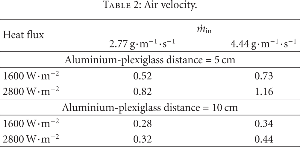
According to the test, when the plexiglass wall is placed in front of the plate, the water film temperature at the bottom of the aluminium plate is lower than that in the case where the plexiglass wall is not in place. When the distance between the aluminium plate and the plexiglass wall is decreased, the transverse area of the chimney decreases. The temperature of the water film, which is more important, induces an acceleration of the air particles in the vicinity of the film. The velocity increases to evacuate the air (Table 2). The intensity of the chimney effect is less important when less heat flux is imposed. The greater the imposed heat flux, the more the steam produced and the greater the chimney effect.
Air velocity.
4.3. Evaporated Mass Flow Rate
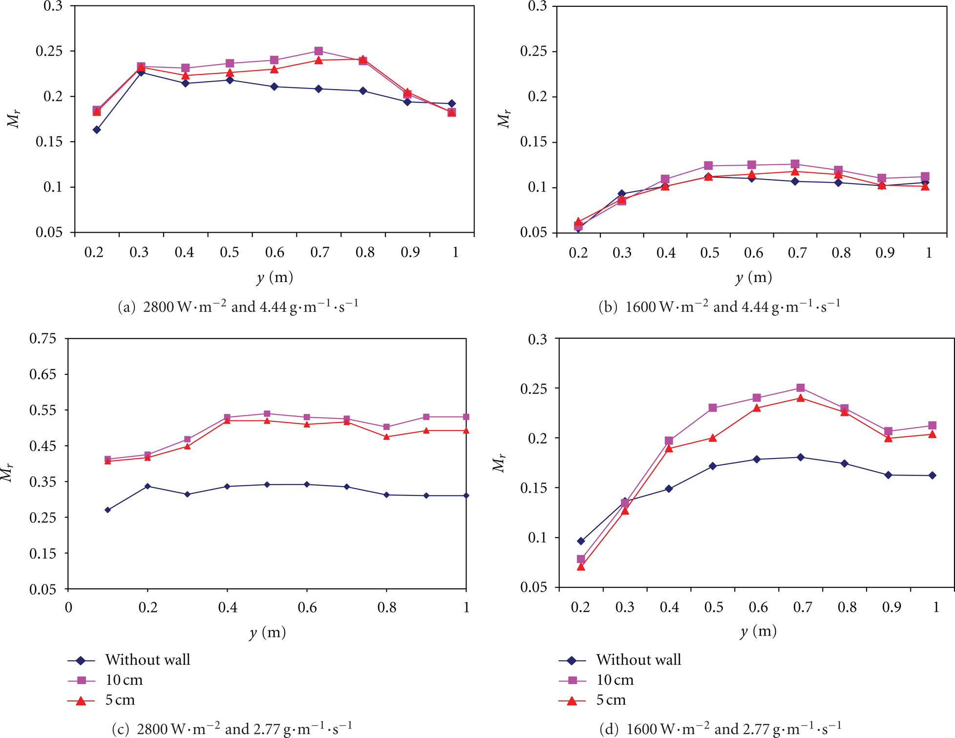
The influence of the mass flow rate of the feed water
Evaporated mass.
The water film temperature, the air speed inside the channel, and the steam concentration at the air-water film interface must be taken into account to explain Figures 6(a)–6(d). When the plexiglass wall is placed in front of the plate, the chimney effect appears and produces the exit of steam at the top of the channel, caused by the acceleration of the wet air inside the chimney at different densities. The pressure inside the chimney decreases and produces the suction of fresh air at the bottom of the plate into the channel. Laminar and turbulent flows are found in the chimney. The thickness of the water film is very small, not exceeding 0.5 mm, and the temperatures along the plate and of the liquid film are practically identical. We use the temperature along the plate to calculate the local Rayleigh number (Figure 7). From

Local Rayleigh number: (a)
4.4. Local Sensible and Latent Nusselt Number
The results are presented in this section in terms of dimensionless numbers. The symbols

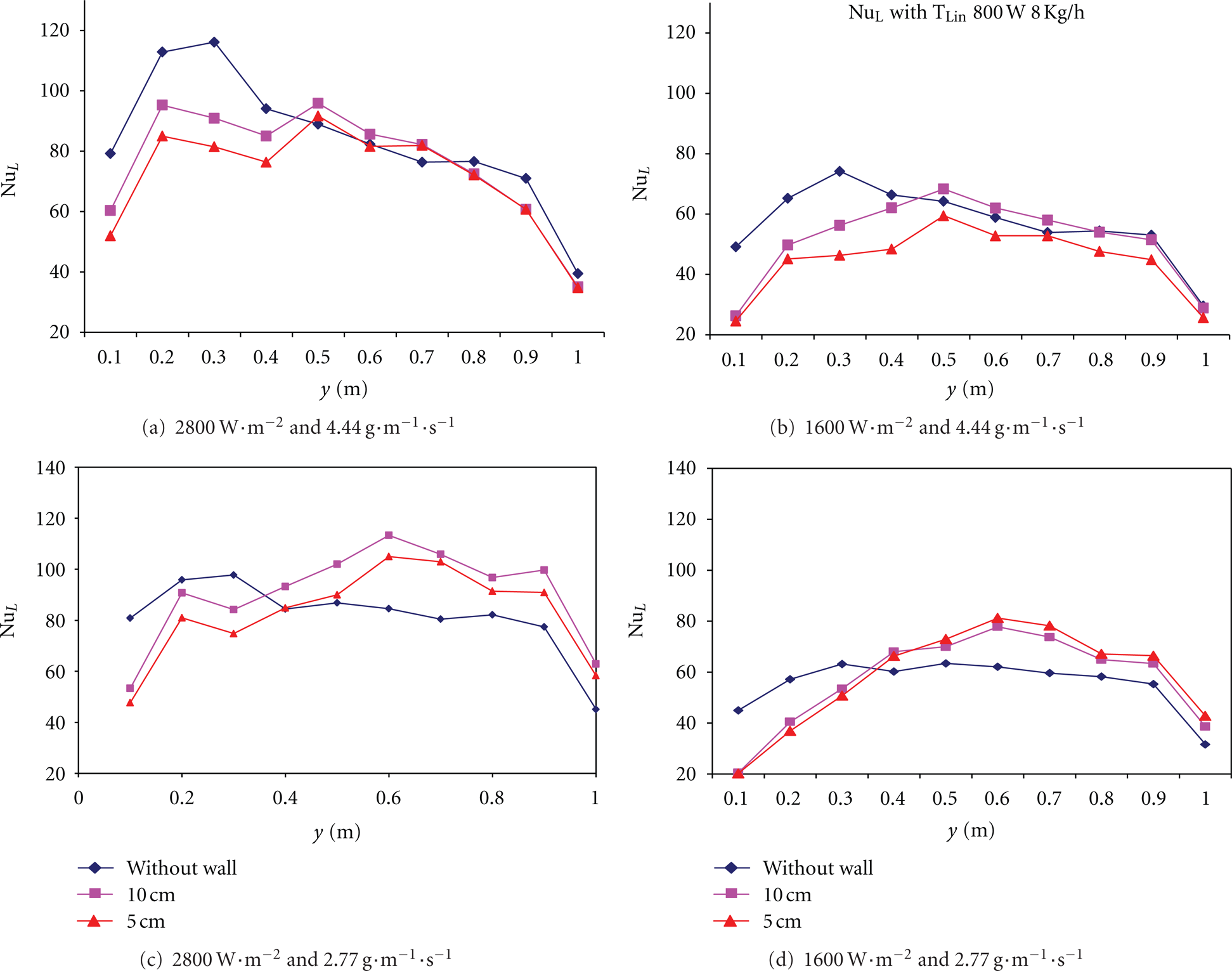
Figures 8(a)–8(d) present the sensible Nusselt numbers for different heat fluxes and mass flow rates with the different geometries. According to Yan and Soong [21], the sensible Nusselt number increases along the aluminium plate. The sensible flux depends on the water temperature and the mass of the liquid over the plate. The flux balance schema shows a water film differential for the different heat fluxes. According to Figures 8(a)–8(d), temperatures always increase along the plate; that is,

Sensible Nusselt number.
When the plexiglass wall is in place, the transition between laminar and turbulent flows causes a maximum, as shown in Figures 8(a)–8(d). The transition and the chimney effect create a higher-intensity speed profile. This profile increases the sensible heat transfer. When the plexiglass wall is not in place, the chimney effect does not occur and the velocity profile is lower. The sensible Nusselt number increases when the aluminium plate is subjected to a higher heat flux. The greater the heat flux imposed, the greater the aluminium plate temperature, so the heat flux through the plate to the water film increases. The last point, which represents the bottom of the plate, does not see an increase because of the uncertainty of the measurement. Negative sensible Nusselt numbers at the top of the plate are explained by taking into account the condensation on the feed tube.
Comparing Figures 8(a)–8(d) and Figures 9(a)–9(d), the most important fact is that the latent Nusselt number is approximately 10 times greater than the sensible Nusselt number. The flux dissipated by evaporation is 10 times greater than the flux that water is able to dissipate by increasing its temperature. The reason that the plots are similar to the ones for the evaporated mass ratio (the first and the last points corresponding to the top and the bottom of the aluminium plate, resp., do not increase because of the uncertainty of the measurements and the numerical process) is that the latent flux depends mainly on the steam produced. Differences between the evaporated mass ratio and the latent Nusselt number without the plexiglass wall are caused by the dependency between the evaporation latent heat and the water temperature. If the two different inlet mass flow rates are compared, as in Figures 9(a)–9(d), lower mass flow rates increase the latent Nusselt number. As explained before, with lower inlet mass flow rates, the main dissipation process is the production of steam.
Latent Nusselt number.
5. Conclusions
The heat and mass transfer for cooling by evaporation were studied for electrical components on the back side of an aluminium plate. Twelve resistors were used to simulate the electrical components and to produce the heat flux in the aluminium plate that was dissipated by evaporation from the opposite side. The experimental results obtained for different operating parameters lead to the following main conclusions.
Temperatures using natural convection are higher than those if water film cooling is used.
With a higher imposed heat flux, higher aluminium plate temperatures are reached.
With a lower inlet mass flow rate, higher aluminium plate temperatures are reached.
When a plexiglass wall is placed near the aluminium plate, higher temperatures are reached.
The higher the imposed heat flux, the higher the evaporated mass ratio.
Without the plexiglass wall, the evaporated mass ratio remains constant along the plate for each imposed heat flux.
The transition between laminar and turbulent flows, which starts at y = 0.7 (Ra = 109), causes the increase in the temperature along the plate and the chimney effect, and the evaporated mass ratio reaches a maximum at y = 0.5.
It is necessary to optimise the aluminium plate—plexiglass wall distance.
The latent flux is approximately 10 times greater than the sensible flux, and as a consequence, it is more effective to produce steam than to increase the water film temperature.
As lower inlet mass flow rates increase steam production, it is necessary to use the lowest possible inlet mass flow rates.
Footnotes
Nomenclature
Dimensionless Numbers
Greeks Symbols
Subscripts
Acknowledgments
The authors would like to acknowledge the financial support provided by the French National Research Agency (ANR) and the Alstom Transport.