
Abstract
This paper describes how the actuation scheme affects the size and shape of the workspace of 3RPR and 3PRR, which are the two popular planar parallel manipulators. This study helps in achieving the required singularity-free zones for a specific task by adopting a suitable actuation scheme without resorting to changing the architecture of the manipulator. In addition, the performance index GCI for each actuation scheme has been evaluated and compared with each other. Finally, the GCI for each actuation scheme has been optimized subjected to the geometric constraints for the 3PRR planar parallel manipulator.
1. Introduction
Parallel manipulators are robots that consist of separate serial chains that connect the fixed link to the moving end-effectors. Even though parallel manipulators possess several advantages like, high stiffness, low inertia, and large payload capacity, they are suffered from limited workspace, complicated singularities, and design difficulties. Many researchers have analyzed kinematics, dynamics, workspace, and control of parallel manipulators. Mohammadi Daniali et al. [1] presented an in-depth study of velocity relationships and singular conditions for general planar parallel robots. Gosselin [2] presents computational algorithms for kinematics and dynamics of planar and spatial parallel robots. Merelt et al. [3] solved the forward pose kinematics for a broad class of planar parallel manipulators. Y. Jin et al. [4] described a 3-limb selectively actuated parallel manipulator (SA-PM) in which the end-effecter exhibits either a 3-DOF spherical, 3-DOF translational, or a complete 6-DOF spatial motion depending on the types of the actuation chosen for the actuators. They also presented singularity analysis of the SA-PM based on geometry for all actuation schemes to facilitate the kinematic design of the manipulator. Arakelian et al. [5] proposed the legs of variable structure for the increase of reachable workspace of a spatial manipulator. Su et al. [6] studied trajectory planning and actuation schemes, which are crucial for their control. Ebrahimi et al. [7] presented a model of an actuation scheme and its effects on the singularities of parallel manipulators for a given path in the workspace. Actuation schemes and actuator relocation for serial planar manipulator have also been studied in detail by Matone and Roth [8] and Ramji et al. [9] respectively. Li and Xu [10] designed a new XYZ novel micromanipulator, which was called a 3-PRC manipulator in order to generate a cuboids’ shape workspace by using the (PZT) piezoelectric actuator to drive the prismatic active joint due to its major advantages of high stiffness and compact size; however, stroke of the adopted PZT cannot meet the application requirements so in order to enlarge the workspace the stroke of the PZT is amplified by using a lever amplification mechanism and making the leg as an equivalent PRPR linkage. Xu and Li [11] proposed a new PRC translational parallel manipulator with orthogonally arranged fixed actuators for producing a singularity-free workspace through an extensive reduction in cost in building and controlling such a manipulator. Li and Xu [12] analyzed the mobility of the 3-PRC translational parallel manipulator via screw theory and also illustrated the effect of architectural parameters on the shape and size of the workspace; further more dexterity characteristics are investigated in the local and global sense for real machine design.
Actuation scheme depends on the Jacobian matrix that transforms the active input joint rates into end-effecter task space velocities. Earlier researchers on PKMs studied the kinematic analysis and performance of the manipulator for only one set of active joint rates (consists of only one joint from one leg) preferably the base joints. Where the kinematic and workspace analysis is not only confined to one set of active joints and also tried to investigate the changes in reachable workspace and performance of manipulators for the other set of joints, which are chosen as active joints. We have to enumerate the optimal geometric parameters like link lengths, joint variables, and orientation of the prismatic joints, which greatly influence the workspace and performance of the manipulator for each possible actuation scheme. Though actuation schemes have been proposed by various researchers, these have not been applied to any specific case except by Rakotomanga et al. [13]. This paper is an attempt to apply the concept of actuation schemes to two popular planar manipulators, namely, 3RPR and 3PRR.
The organization of the paper is as follows: Method explains the basic theory of architecture, kinematic modeling, and actuation schemes of 3RPR manipulator first, followed by a similar treatment for the 3PRR manipulator. Results describes through graphs and tables, comparison of the performance of a manipulator for all possible actuation schemes. Also included is the optimal geometric design of 3PRR planar parallel manipulator. These results are followed by Discussion.
2. Method
2.1. Mechanism Architecture of 3RPR Planar Manipulator
The manipulator considered here is symmetric and consists of three identical legs connecting the fixed base to the end-effecter as shown in Figure 1. The three revolute joints are located on the fixed base triangle at A i and another three revolute joints are located on the moving triangle at C i where i = 1,2,3. The prismatic joint variables L i correspond to the leg lengths A i C i . The moving frame {H} is located at the centroid of the end-effecter, which is an equilateral triangle as shown in Figure 2. The fixed frame {B} is chosen at the origin of one of the legs on the fixed base, which is also an equivalent triangle.

3RPR planar manipulator.

End-effecter.
For the 3RPR manipulator, the workspace limitations are due to the limitations of prismatic actuators, and the maximum and minimum lengths of the prismatic actuators of the ith chain are denoted by L
max,i
, L
min,i
, respectively, as the prismatic joint variables. The maximum possible geometric workspace of 3RPR manipulator is the intersection of three annular regions A
i
P centered in A
i
whose radii are

The possible workspace of 3RPR manipulator.
2.1.1. Kinematic Modeling of 3RPR Parallel Manipulator
The solutions are found using the distance norm constraint

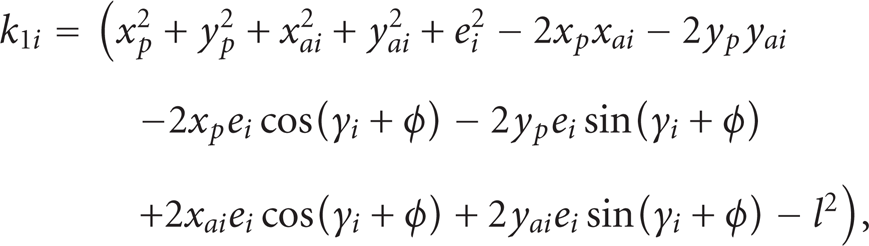
In the forward pose kinematics for the given prismatic joint lengths

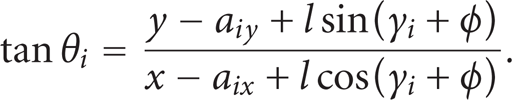
where ϕ is the orientation of the moving platform with reference x-axis, γ i is angle between vector C i P and x-axis of the moving platform, l is length of vector C i P, and a i is distance of the vertex A i of the fixed platform from the origin of the reference frame. The revolute joint angle, which is attached to the fixed platform, is expressed as

It is expressed in analytical form as
2.1.2. Actuation Schemes and Velocity Analysis
The major disadvantage of parallel kinematic chains is their limited workspace and in order to overcome this, recently some researchers have investigated hybrid serial-parallel manipulators that present a compromise between the high rigidity of parallel manipulators and the extended workspace of serial manipulators. However, the usefulness of this manipulator is also limited because the compliance of the manipulator is more, and so it leads to inaccuracy in controlling the manipulator. There is another trend to eliminate the singularities and increase the workspace by the redundant actuation with the use of more than one actuator in a leg. However, this redundant actuation is expensive due to the additional actuators and the complication in controlling the manipulator.
The actuation scheme is the set of active input joint rates of the manipulator in which only one joint from each leg is to be selected. Each actuation scheme has its own singularity free zones of the end-effecter. Since each scheme implies a different set of actuator motions, this leads to different movements of the end-effecter. A proper actuation scheme not only avoids singularities of the workspace but even enhances the stiffness and accuracy of the manipulator.
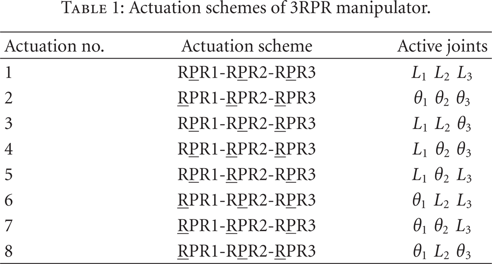
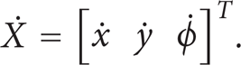
The 3RPR manipulator can be actuated either by revolute joint or by prismatic joint in each leg so to attain the required end-effecter output velocities
Actuation schemes of 3RPR manipulator.
2.1.3. Jacobian Matrix
The velocity vector of a point is given in two different directions of a loop closure. Each loop closure consists of a fixed base, moving platform, and all links of a leg. The unactuated joint rates in each leg are eliminated by taking dot product of the velocity vector loop equation with a vector that is normal to all vectors of unactuated joint rates. Finally the resulting equations are assembled into a Jacobian matrix. In order to obtain the Jacobian matrix for the actuating jointL i differentiate (2) with respect to time and is expressed as

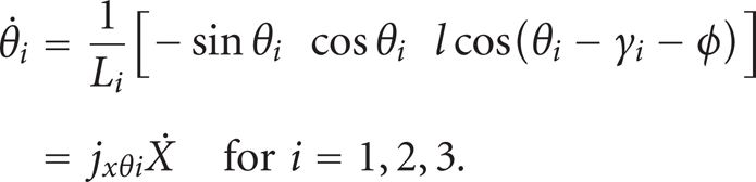
The Jacobian for the actuating joint θ
i
is obtained by differentiating (4) with respect to time and is expressed as
Using the above equations (5) and (7), the Jacobian matrix for eight actuation schemes is expressed as

For actuation scheme 1 (R

where

Which is analogous to the

2.2. 3PRR Manipulator Architecture
A 3-DOF planar parallel manipulator with three identical legs, which has been studied extensively by many researchers including Zhang et al. [16], is shown in Figure 4. Each kinematic chain is of PRR type and consists of one prismatic joint and two revolute joints. The manipulator is intended to position and orient the equilateral triangle-shaped platform
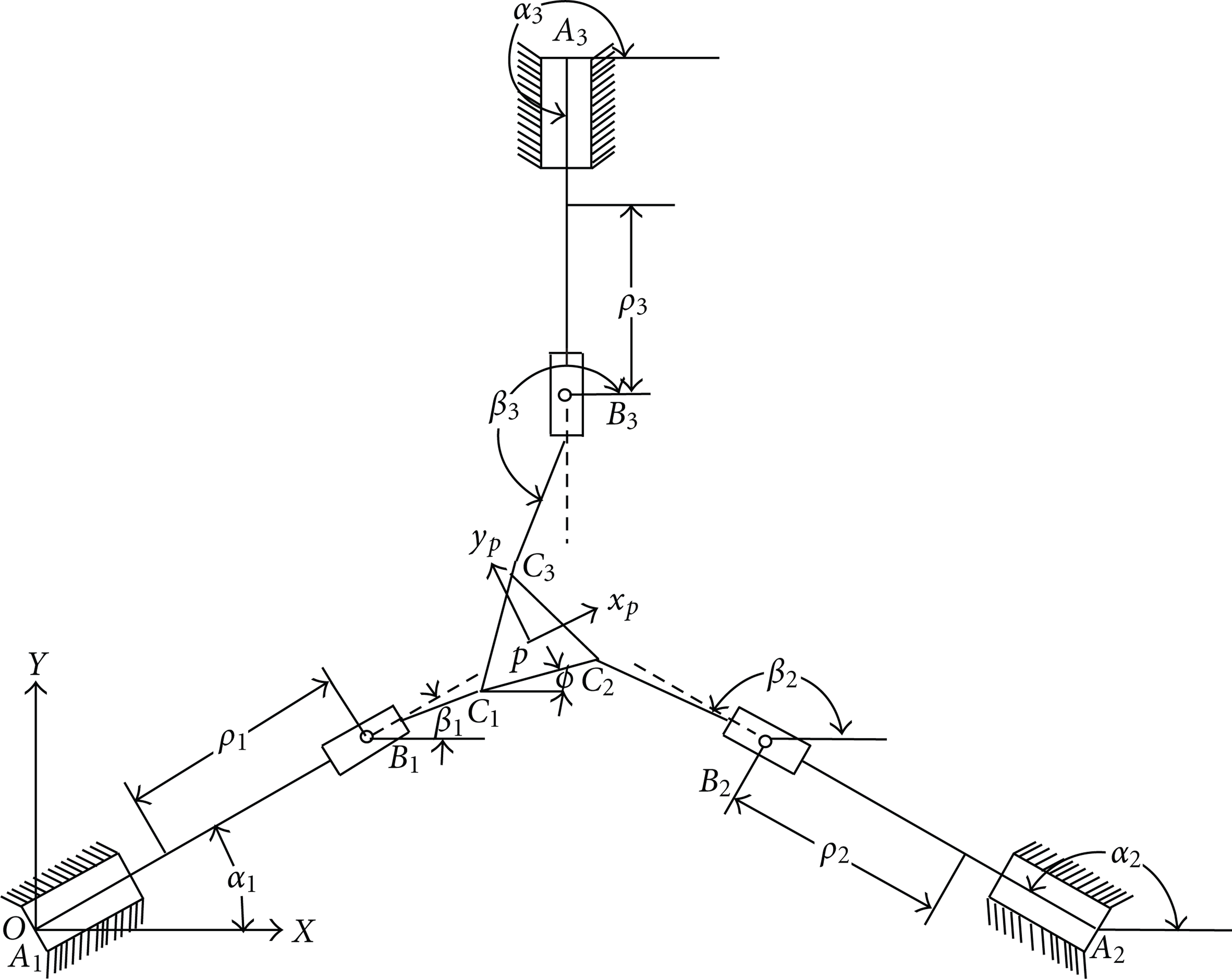
3PRR planar manipulator.
The base of the manipulator, also an equilateral triangle with vertices A1, A2, and A3, is fixed to the ground. The joint coordinate associated with the ith actuator that actuates the prismatic joint is ρ
i
for i = 1,2,3. The variable α
i
is the angle at A
i
between the x-axis of the fixed frame and ith linear guide

Writing the above equation in component form,

Using (11) and (12), we can establish a quadratic equation in ρ
i


It is clear that there are two possible solutions for each individual link, and the manipulator can take on a maximum of eight configurations for a given set of coordinates of the moving platform.
2.2.1. Velocity Analysis of Actuation Schemes
The 3RPR manipulator can be actuated either by revolute joint or by prismatic joint in each leg of the manipulator in order to attain the required end-effecter output velocities. Thus there are only three input joint rates out of six

where 
The above equation can be expressed as

Equation (19) presents the velocity relationship between the sliders and the platform with the Jacobian matrix J
P
. Using (19) for i = 1,2,3, we can write Jacobian matrix for actuation scheme 1 (
actuation schemes for 3PRR manipulator.

Performing vector cross product to (17) by 
From (19) and (20), the angular velocity of the link is given as

Using (21) we have to get Jacobian matrix for the actuation scheme 2 represented as (P
2.2.2. Dexterity Indices
Yoshikawa [17] proposed the concept of kinematics manipulability as

where J is the Jacobin matrix and depends on the instantaneous configuration of the manipulator defined by a joint vector q. This index is treated as a quantitative measure of the easiness to arbitrarily change the position and orientation at a certain posture. The significance of manipulability is the measure of the fast recovery ability from the escapable singular point for the redundant manipulator. Manipulability has two problems: scale and order deficiencies. Those problems prevent the fair comparison among the manipulators with different dimension and make it impossible to derive the physical meaning of the manipulability. Trying to eliminate the order dependency, Kim and Khosla [18] gave another way to calculate manipulability

where m is the number of degrees of freedom of the manipulator.
Another usually used index is the condition number of the Jacobian matrix that is expressed as
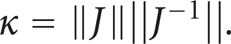
Condition number signifies the error amplification factor between the joint rate errors in to task space errors. The condition number depends on the manipulator configuration, link lengths. It varies from one at isotropic configurations to infinity at singular configurations so this is also defined as the measure of degree of ill-conditioning of the Jacobian matrix. Both indices, condition number and manipulability, are local measures of performance at a particular pose of the end-effecter within the workspace region; using these indices, we cannot compare the performance of any two different manipulators for their usefulness. In order to evaluate the global behavior of a manipulator over the workspace, a global index is proposed by Gosselin and Angeles [19] as

where W is the workspace and κ is the condition number. In other sense, GCI is average value of 1/κ over workspace region; it represents the uniformity of dexterity over the entire workspace so this index makes sense for the optimal design of manipulator for which the average value performance is an important design factor.
3. Results and Discussion
3.1. Performance of Actuation Schemes for 3RPR Manipulator
Symmetric architectures are considered here since they are widely used in practice. The values chosen for the sides of the fixed link are
The reachable workspace for all eight actuation schemes using the Monte Carlo algorithm is plotted and is shown in Figure 5. The Global Condition Index (GCI) for each actuation scheme within the maximum possible reachable workspace is computed, and the results are shown in Table 3. Actuation scheme 1 (R
GCI of actuation schemes at A1 A2 = 12 m, C1C2 = 2 m; [Li min Li max] = [5 9] m.


Workspace of actuation schemes for 3RPR manipulator.
3.1.1. Effect of Geometric Parameters on GCI
The performance values shown above pertain to one set of dimensions, and obviously these need not necessarily be the best. Hence various dimensions have been tried out keeping in mind that generally linear actuators are available in standard sizes. Of all possible combinations, the optimum ones based on GCI have been determined and the results have been plotted as shown in Figure 6. The variables considered are maximum length of the linear actuator Li max and the size of the end-effecter (l) for the given Li min = 5 m and the base platform
Design variables corresponding to maximum GCI for all eight possible actuation schemes for 3RPR parallel manipulator at A1A2 = 12 m, C1C2= 2 m; L imin = 5 m.


Effect of design variables on GCI of 3RPR manipulator.
It can be seen that the global maximum of all GCIs occurs for actuation scheme 1 (R
3.2. Workspace and Performance Evaluation of 3PRR
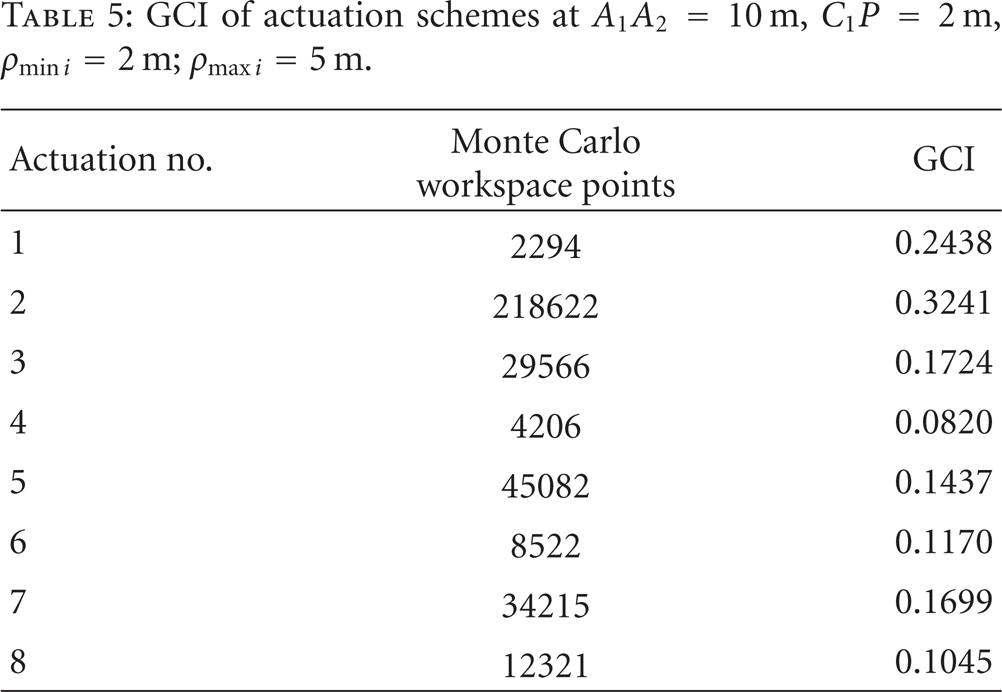
Precise calculation of workspace and its boundaries is important because they influence the dimensional design, manipulator's positioning in the work environment, and its dexterity within the reachable workspace. The workspace is limited by the boundary obtained through solving inverse kinematics, reachable extent of drives and joints, and the occurrence of singularities. A numerical example of the force-unconstrained poses of the 3PRR planar manipulator is presented. Both fixed and moving platforms are equilateral triangles, whose sides are
GCI of actuation schemes at A1A2 = 10 m, C1P = 2 m, ρ mini = 2 m; ρ maxi = 5 m.

Workspaces for actuation schemes of 3PRR manipulator.
3.2.1. Optimization of Geometric Structure for 3PRR Manipulator
Sequential quadratic programming (SQP) methods attempt to solve a nonlinear program directly rather than convert it to a sequence of unconstrained minimization problems. The basic idea is analogous to Newton's method for unconstrained minimization. At each step, a local model of the optimization problem is constructed and solved, yielding a step toward the solution of the original problem. A quadratic approximation to this function is now constructed and so along with linear constraints forms a quadratic programming problem that is, the minimization of a function quadratic in the variables, subject to linear and nonlinear constraints. The solution of the original optimization problem, say
The objective of this optimization algorithm is to determine optimal dimensions and optimal performance index for the eight actuations for the three legged parallel manipulators for a specified task. The optimization algorithm solves a nonlinear constrained optimization problem defined as follows:

For the given βmin i = 0°,
Optimized design variables for various actuation schemes at ρ mini = 2 m; ρ maxi = 5 m.
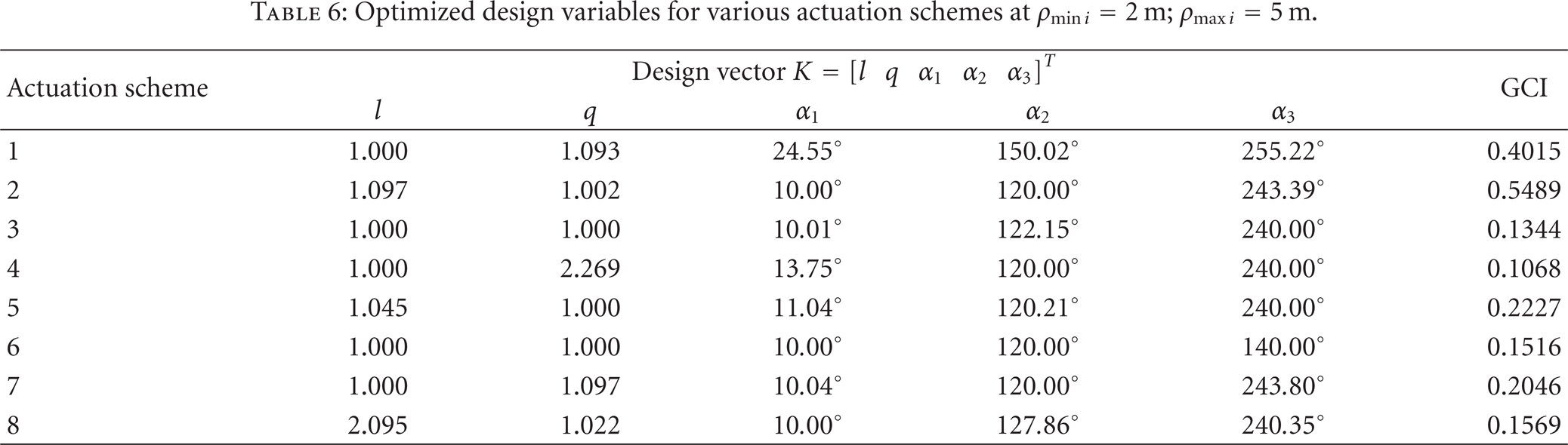
Actuation scheme 2 (P
4. Conclusions
Kinematic analysis of 3RPR and 3PRR parallel manipulators with symmetric properties is presented in this paper. In this problem, actuation scheme is identified as one of the design variables of the mechanism. It is shown that actuation scheme affects the performance of the manipulator and size and shape of the workspace significantly. The dimensional synthesis for optimization of Global Condition Index for each actuation scheme is presented.
Thus this paper offers a methodology to choose the ideal actuation scheme so as to attain the best performance of the manipulator with desired workspace; this is illustrated on two planar 3PRR and 3RPR manipulators as an example. The same technique can be applied to other planar PKMs.