
Abstract
Temperature-compensated damage monitoring in steel girder connections by using wireless acceleration-impedance sensor nodes is experimentally examined. To achieve the objective, the following approaches are implemented. Firstly, wireless acceleration-impedance sensor nodes are described on the design of hardware components to operate. Secondly, temperature-compensated damage monitoring scheme for steel girder connections is designed by using the temperature compensation model and acceleration-impedance-based structural health monitoring methods. Finally, the feasibility of temperature-compensated damage monitoring scheme by using wireless acceleration-impedance sensor nodes is experimentally evaluated from damage monitoring in a lab-scaled steel girder with bolted connection joints.
1. Introduction
Steel structures have structural connections such as bolted joints. Potential damage types of the structural connections include fatigue cracks between bolt holes, the change in tensile force of bolts, and failures of connection components. Structural health monitoring (SHM) on those structural connections becomes an important topic since damage occurred in structural connections, which is not detected or remedied appropriately, may result in local failure, reduction of load carrying capacity, or catastrophic disaster [1].
Up to date, many studies have been focused on SHM of structural connections by using global and local dynamic characteristics [2–11]. These studies have been mainly focused on developing SHM methods by using a single physical quantity such as strain, acceleration, or electromechanical impedance. However, the reliability of SHM methods using a single sensing device is relatively low compared to the case of multiphysical quantities. Therefore, the SHM scheme using multiscale sensing mechanism can be an alternative approach [12–15].
Also, the high costs associated with wired SHM systems can be greatly reduced through the adoption of wireless sensors. An advantage of wireless sensor is that the automated operation can be implemented by embedded operation software. This fact leads to a new paradigm that adopts smart sensors for autonomous and cost-efficient SHM [16–22]. Straser and Kiremidjian [23] first proposed a design of a low-cost wireless modular monitoring system (WiMMS) for SHM applications. Lynch et al. [24] improved the performance of WiMMS in which acceleration-based damage monitoring algorithms are embedded. Nagayama et al. [25] used Imote2 sensor platforms from Memsic Co. [26] for acceleration-based SHM of truss structures. Park et al. [14] developed acceleration-based and impedance-based smart sensor nodes (Acc-SSN and Imp-SSN) which are modified from the sensor nodes by Lynch et al. [24] and Mascarenas et al. [27], respectively.
However, there still exist two issues that should be solved before real applications on SHM methods of steel girder bridges in the field. Firstly, the temperature-driven variability of structural response data should be quantified in the determination of features such as modal parameters or impedance signatures. Therefore, an issue arises on how to distinguish the temperature-induced variability on feature extraction. Secondly, the detected output may be true, false-positive, or false-negative. Even in the true case, moreover, damage-localization error and severity-estimation error are inevitable due to the temperature effect [28, 29].
In this paper, temperature-compensated damage monitoring in steel girder connections by using wireless acceleration-impedance sensor nodes is experimentally examined. Firstly, wireless acceleration-impedance sensor nodes are described on the design of hardware components to operate. Secondly, temperature-compensated damage monitoring scheme for steel girder connections is designed by using acceleration-impedance-based SHM methods. The temperature compensation model selected the linear regression analysis. The acceleration-based SHM methods selected the correlation coefficient of power spectral density and frequency-based damage index. The impedance-based SHM method selected the correlation coefficient of impedance. Finally, the feasibility of temperature-compensated damage monitoring scheme by using wireless acceleration-impedance sensor nodes is experimentally evaluated from damage monitoring in a lab-scaled steel girder with bolted connection joints.
2. Wireless Acceleration-Impedance Sensor Nodes
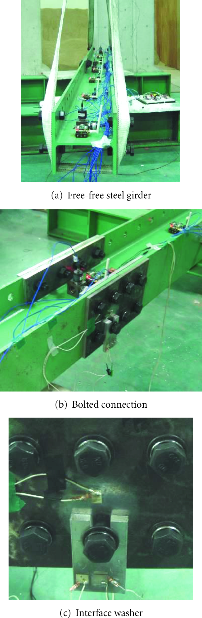
A wireless acceleration-impedance sensor node can be defined as a sensor node to simultaneously measure multiple physical quantities from structures in different scales. For the SHM using acceleration and impedance measurements, a wireless acceleration-impedance sensor node on Imote2 platform is designed as shown in Figure 1. The Imote2 sensor platform was selected to control peripheral devices such as microcontroller, wireless radio, and memory. For acceleration measurement, a SHM-A sensor board developed by Rice and Spencer [30] was selected. For impedance measurement, an SSeL-I sensor board developed by Kim et al. [1] was selected. As shown in Figure 2(a), the prototype of the multiscale sensor node is consisted of four layers. The first and second layers are a battery board (IBB2400) and the Imote2 sensor platform (IPR2400), respectively. The third and fourth layers are the SHM-A acceleration sensor board and the SSeL-I impedance sensor board, respectively.

Design of acceleration-impedance sensor nodes on Imote2-platform.

Prototypes of acceleration-impedance sensor nodes on Imote2-platform.
The Imote2 sensor platform incorporates a low-power X-scale process, PXA27x, and a wireless radio, CC2420. The microcontroller PXA27x runs for multiple tasks which include operation schedule, system control, and radio transmission. Also, the Imote2 has 256 kB of integrated SRAM, 32 MB of external SDRAM, and 32 MB of program flash memory. The memory repository will guarantee to store large amount of data measured by a group of accelerometers and PZT patches. The data processing speed of the Imote2 is faster enough to provide good computational capability and the transmitting distance can be expanded up to 125 m by using an external antenna.
As shown in Figure 2(b), the SHM-A sensor board was selected for acceleration measurement. The SHM-A sensor board should have suitable capabilities for key components such as accelerometer, noise density, antialiasing filter, and analog-to-digital converter (ADC). The sensor board provides three axis acceleration sensor (LIS344ALH) with relative low noise level, light sensor (TSL2561), and temperature and humidity measurements (SHT11). Also, the 4-channel 16-bit high-resolution analog-to-digital converter (ADC) with digital antialiasing filters (QF4A512) is adopted. The ADC converts analog signal to digital data by 16-bit resolution but it guarantees 12-bit resolution. By adopting the digital filters, the sensor board provides user-selectable antialiasing filters and sample rates that can meet a wide range of application demands for infrastructure monitoring.
As shown in Figure 2(c), the SSeL-I sensor board was selected for impedance-based SHM. The SSeL-I is consisted of an impedance converter AD5933, two pull-up resistors for I2C communication, two capacitors for bypassing noises, a connector to a PZT patch and two connectors to the SHM-A sensor board, and the Imote2 sensor platform. Two pull-up resistors are utilized for I2C interface communication between the SSeL-I board, and the Imote2 platform. The microcontroller PXA27x and wireless radio CC2420 in the Imote2 platform are utilized for the impedance measurement. The AD5933 impedance converter has the following embedded multifunctional circuits: function generator, digital-to-analog (D/A) converter, current-to-voltage amplifier, antialiasing filter, A/D converter, and discrete Fourier transform (DFT) analyzer. The AD5933 converter outputs real and imaginary values of impedance signatures for a target frequency of interest and transmits the values into a microcontroller.
3. Temperature-Compensated Damage Monitoring Scheme
Kim et al. [1] proposed a hybrid damage monitoring scheme by using acceleration and impedance signatures. Based on this study, the temperature-compensated damage monitoring scheme is designed as schematized in Figure 3. It consists of three phases: (1) global damage monitoring in overall structure and local damage monitoring in critical sub-structural points by temperature compensation, (2) damage-occurrence alarming and damage-type identification by temperature compensation, and (3) damage localization and severity estimation by temperature compensation of the identified damage.

Temperature-compensated damage monitoring scheme for steel girder connections.
In Phase 1, the damage occurrence is globally monitored by measuring acceleration responses from the target structure. At the same moment, the damage occurrence is monitored at local critical members by measuring changes in electromechanical impedance signatures. Firstly, a global damage-monitoring method using CC of PSD [1] and control chart analysis [31] is implemented to monitor damage occurrence in the entire structure. If any damage occurs in the structure, the acceleration responses would be affected and consequently the CC of PSD values would be decreased. Secondly, local damage monitoring method using CC of impedance [32] signatures and control chart analysis is selected to monitor the occurrence of damage at the local sensor-vicinity zone. The electromechanical impedance is sensitive to the sensor-vicinity zone but almost insensitive to the remaining structure, which makes it feasible to be indicative for the occurrence of damage in localized area.
In Phase 2, the occurrence of damage is alarmed and the type of damage is locally identified by recognizing patterns of the CC of PSD/impedance features [1]. The alarmed damage is classified (localized) as damage occurred at specific locations (i.e., prescribed damages: girder stiffness loss by bolt loosen) or elsewhere in the structure. There are four possible patterns of damage alarming situations: (1) no damage alerted either globally or locally, (2) damage alerted both globally and locally, (3) damage alerted globally but not locally, and (4) damage alerted locally but not globally. In the first pattern, no damage would be occurred in the structure if the acceleration-based monitoring does not alert damage occurrence in the entire structure and the impedance-based monitoring does not alarm damage occurrence at the local zone. In the second pattern, damage would be apparently occurred at the local critical zone if the acceleration-based monitoring alarms the occurrence of damage in the structure and the impedance-based monitoring also alarms the occurrence of damage at the local zone. In the third pattern, damage might be occurred elsewhere than the preselected local zones if the acceleration-based monitoring alarms the occurrence of damage in the structure but the impedance-based monitoring does not indicate the occurrence of damage at the local zones. In the final pattern, incipient small damage would be occurred at a local critical zone if the acceleration-based monitoring does not alert damage occurrence but the impedance-based monitoring indicates damage occurrence at the local zone.
In Phase 3, the location and severity of the identified damage by using frequency-based damage index method are estimated in details. The damage estimation by using frequency-based damage index method is performed by a few temperature-compensated natural frequencies of target structures.
3.1. Temperature Compensation by Linear Regression Analysis
Regression analysis gives information on the relationship between a response variable and one or more independent variables to the extent that information is contained in the data. The goal of regression analysis is to express the response variable as a function of the predictor variables. The duality of fit and the accuracy of conclusion depend on the data used.
Once a regression analysis relationship is obtained, it can be used to predict values of the response variable, identify variables that most affect the response, or verify hypothesized causal models of the response. The value of each predictor variable can be accessed through statistical tests on the estimated coefficients (multipliers) of the predictor variables. An example of a regression model is the simple linear regression model which is a linear relationship between response variable, y, and the predictor variable, x, of the form

3.2. Damage Alarming by CC of PSD
Assume that two acceleration signals

The correlation coefficient of PSDs (CC of PSDs) represents the linear identity between the two PSDs obtained before and after a damage event:


3.3. Damage Alarming by CC of Impedance
The active material is described by its short-circuited mechanical impedance, which is powered by voltage or current. The host structure is modeled as the effect of mass, stiffness, damping, and boundary conditions. When a piezoelectric patch is surface-bonded to a structure, the electrical admittance (the inverse of electromechanical impedance) of the patch,
Equation (5) indicates that the electrical impedance of the piezoelectric patch bonded onto a host structure is directly related to the mechanical impedance of the structure. The first term of the equation is the capacitive admittance of the free piezoelectric patch. The second term includes the mechanical impedance of both the piezoelectric patch and the host structure. When damage occurs to a structure, its mechanical impedance will be shifted. Hence, any changes in the electrical impedance signature (such as magnitude of admittance and resonant frequency) are attributed to damage or changes in the structure.
To quantify the change in impedance signature due to damage in the structure, the CC of impedance signatures measured before and after damage [32] is used in this study. The CC is calculated from impedance measurements before and after damage as

3.4. Damage Estimation by Frequency-Based Damage Index
Kim et al. [34] proposed a frequency-based damage index algorithm for a structural system of
As the ith modal information is available for the system, a damage index (DI) for the jth location can be defined as follows:


The condition


4. Experimental Setup and Damage Scenarios
4.1. Target Structure and Sensor Layout
A lab-scaled steel girder model with bolted connections was used to evaluate the performance of the temperature compensated damage monitoring scheme. As shown in Figures 4 and 5, the girder is H-section (H-

Schematic of Bolt-connected steel girder.
Experimental setup of Bolt-connected steel girder.
The structure was tested in a lab (Smart Structure Engineering Lab) located at Pukyong National University, Busan, Korea. A series of tests were performed from 22 July, 2010 to 22 January, 2011. When these tests were performed, temperature varied between 5.7°C and 29.9°C as shown in Figure 6. Temperature, acceleration, and impedance data were measured and recorded on every one hour. Temperatures had been measured by using K-type thermocouple wires and KYOWA (EDX-100A) Temperature Logger.
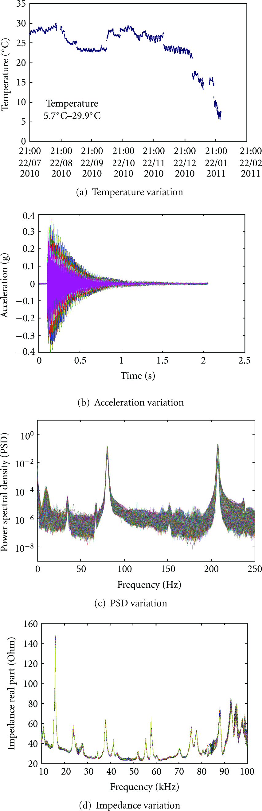
Temperature, acceleration, and impedance variation during test.
4.2. Temperature Compensation Results by Linear Regression Analysis
The temperature-compensated damage monitoring of steel girder connections was performed after compensation between temperature and acceleration/impedance. The temperature compensation of temperature acceleration and temperature impedance was extracted by the linear regression analysis. In statistics, regression analysis includes many techniques for modeling and analyzing several variables, when the focus is on the relationship between a dependent variable and one or more independent variables. The linear regression analysis is the simplest approach to analyze the relationship between a response variable (y) denoted acceleration/impedance response features and a predictor variable (x) denoted temperature. And the linear regression analysis is classified into simple linear regression and polynomial regression. The simple linear regression is the least squares estimator of a linear regression model with a single predictor variable. The polynomial regression is a form of linear regression in which the relationship between the predictor variable and the response variable is modeled as nth order polynomial. Figures 7–9 show the results of linear regression analysis between acceleration/impedance response features and temperature by using simple linear and polynomial regression model. The linear relationship of temperature and acceleration and impedance features was extracted from the reference data at the temperature of 29.9°C. As shown in Figure 7, CC of PSD presents about 3~40% error between simple linear regression and polynomial regression on temperature variation. And CC of impedance presents about 8~17% error in Figure 8. The natural frequencies present about less 1% error between simple linear regression and polynomial regression in Figure 9. Those results show that the natural frequencies show linear dependence with temperature variation although there is no clear linear dependence between CC of PSD and temperature. In despite of this error, the simple linear regression analysis is selected for providing good performance for wireless acceleration-impedance sensor node.
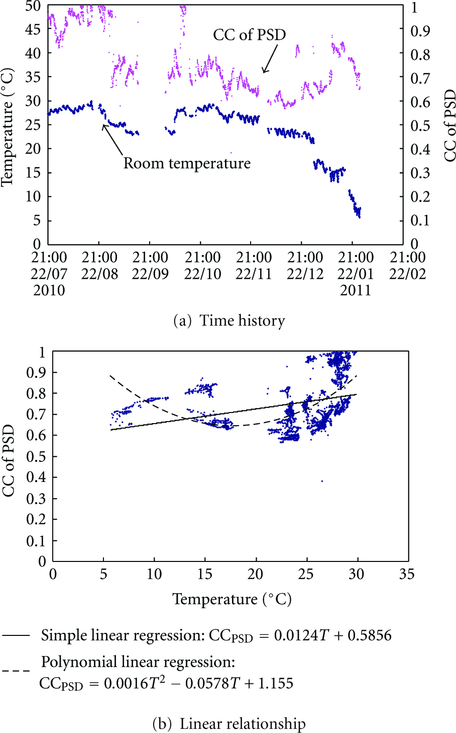
Time history and linear relationship between temperature and CC of PSD.
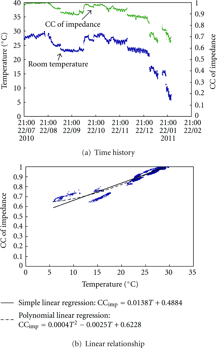
Time history and linear relationship between temperature and CC of impedance.

Linear relationship between temperature and natural frequencies.
The temperature compensation between temperature and CC of PSD was extracted by the linear regression. Figure 7(a) shows the time history between CC of PSD and temperature by using the measured data during 6 months. Figure 7(b) shows the linear regression analysis results between temperature and CC of PSD. By these analysis results, CC of PSD was changed 0.0124 to values by temperature change of 1°C.
The temperature compensation between temperature and CC of impedance was extracted by the linear regression analysis. Figure 8(a) shows the time history between CC of impedance and temperature by using the measured data during 6 months. Figure 8(b) shows the linear regression analysis results between temperature and CC of impedance. By these analysis results, CC of impedance was changed to 0.0138 values by temperature change of 1°C.
The temperature compensation between temperature and natural frequencies was extracted by the linear regression analysis. Figure 9 shows the linear regression analysis results between temperature and natural frequencies. By these analysis results, the first natural frequency (Mode 1) was changed to 0.029 values by temperature change of 1°C. And the second natural frequency (Mode 2) was changed to 0.032 values by temperature change of 1°C.
4.3. Damage Scenarios
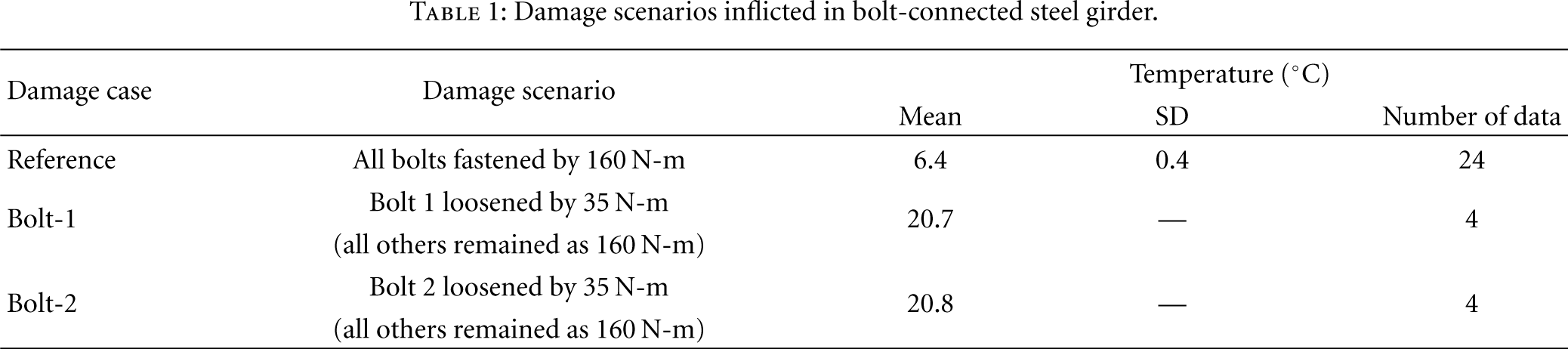
The bolt loosen was selected for general damage type of steel girder connections. Table 1 shows damage scenarios for bolt loosen of the steel girder connections. The damage scenarios include one reference and two bolt-loosen damage cases. The reference case is that all bolts are fastened by torque of 160 N-m. The damage cases are loosened to torque of 35 N-m by Bolt-1 and Bolt-2. The temperature variations (
Damage scenarios inflicted in bolt-connected steel girder.
5. Temperature-Compensated Damage Monitoring Results
5.1. Damage Alarming Results
The temperature-compensated damage alarming was performed by using acceleration-impedance-based SHM results. Firstly, the acceleration-based SHM results presented the change of global structural behavior by using the temperature-compensated CC of PSD in steel girder connections. Secondly, the impedance-based SHM results presented the change of identified local structural behavior (by the location of contacted PZT patch) by using the temperature-compensated CC of impedance.
For Reference and two damage cases (Bolt-1 and Bolt-2), acceleration and impedance signals up to twenty-four and four ensembles were measured from Loc. 4 sensor. As shown in Figure 10, twenty-four ensembles of the Reference (acceleration and impedance) were used to decide an LCL for damage alarming. An LCL mean (standard deviation) value is 0.9954 (0.0041) for CC of PSD. When the CC of PSD is dropped under LCL, the damage monitoring scheme makes a decision to make global damage in steel girder connection. An LCL mean (standard deviation) value is 0.9910 (0.0045) for CC of impedance. When the CC of impedance is dropped under LCL, the damage monitoring scheme makes a decision to make identified local damage in steel girder connection.

Temperature-compensated damage monitoring results.
As the effect of temperature compensation, Bolt-2 was successfully alerted by both the wireless system before and after temperature compensation. These results apparently decided that damage type is classified Bolt-2 damage. The PZT patch is directly contacted Bolt 2. So, Bolt-2 should be detected as damage by LCL analysis of CC of impedance regardless of temperature compensation. The temperature compensation of this result shows only improvement of damage grade in alarmed Bolt 2 (compared before temperature compensation, CC of PSD/impedance had adjacent value on decided LCL). As secondly case, Bolt-1 apparently presents the effect of temperature compensation. In Bolt-1, the results before temperature compensation alarms damage occurrence by dropping under LCL of CC of PSD/impedance. Bolt-1 damage was not detected by CC of impedance (PZT patch is directly contacted Bolt 2). This result was shown to be false alarming result. Then, Bolt-1 damage was not alarmed by CC of impedance after temperature compensation. These results apparently decided that damage type is the damage of other location except classified Bolt-2 damage.
5.2. Damage Estimation Results
Although damage case Bolt-2 did not present the effects of temperature compensation, the two damage cases were apparently alarmed and classified to correct damage types. Then, the temperature-compensated damage estimation was performed based on these results. The damage estimation performed to predict damage location and size by using frequency-based damage index method. The frequency-based damage index method needed initial natural frequencies and mode shape. The natural frequencies used extracted values of Reference and two damage cases. Also, the mode shape only used extracted values of Reference. Based on these facts, the frequency-based damage index method was important to extract accurate natural frequencies before and after damage sates. Modal parameters (natural frequency and mode shape) were extracted from acceleration signals measured at the seven sensor locations (i.e., Loc. 1–Loc. 7) by using the frequency domain decomposition method [35, 36].
For the Reference and the two damage cases, the corresponding natural frequencies measured by before and after temperature compensation are listed in Table 2. Then modal curvatures were analyzed from the postprocessed mode shapes, from which modal strain energies of girder elements were computed. As shown in Figure 11, the damage locations were predicted by using modes 1 and 2. In case of Bolt-1, the predicted damage location has some error. But, in case of Bolt-2, the predicted damage location has correctly predicted real damage location. The predicted damage size of Bolt-2 damage has big difference value (0.660) compared with real damage size (0.261). The difference considered that the method for calculating real damage size by using second moment of area (I) had error. In the future, we will investigate the study for calculating real damage size of bolt-connection damage.
Natural frequencies before and after temperature compensation for steel girder connection.


Temperature-compensated damage estimation results.
6. Conclusions
In this paper, temperature-compensated damage monitoring in steel girder connections by using wireless acceleration-impedance sensor nodes is experimentally examined. To achieve the objective, the following approaches are implemented. Firstly, wireless acceleration-impedance sensor nodes are described on the design of hardware components to operate. Secondly, the temperature-compensated damage monitoring scheme for detecting bolt loosening, as typical damage type of steel girder connections, is designed by using acceleration-impedance-based SHM methods. The temperature compensation selected the linear regression analysis model to extract linear model between temperature and acceleration-impedance responses. The acceleration-based SHM methods selected the correlation coefficient of power spectral density and frequency-based damage index. These SHM methods performed damage alarming, classification, and damage estimation for detecting bolt loosening. The impedance-based SHM method is selected the correlation coefficient of impedance. This SHM method performed damage alarming and classification for detecting bolt loosening. Finally, the feasibility of temperature-compensated damage monitoring scheme by using wireless acceleration-impedance sensor nodes is experimentally evaluated from damage monitoring in a lab-scaled steel girder with bolted connection joints.
From the experimental results, damage monitoring results for bolt-connection damage show obvious improvement result by temperature compensation. Also, the wireless sensor nodes are applied to improve temperature-compensated damage monitoring scheme by considering recently new paradigm in SHM. However, the damage estimation results to predict damage size have some error compared with real damage size. By solving this difference, the temperature-compensated damage monitoring scheme will improve to construct SHM system for steel girder connections.
Footnotes
Acknowledgments
This work was supported by the National Research Foundation of Korea through a grant funded by the Korean Government (Ministry of Education, Science and Technology (NRF-2011-1-D00063)). The student involved in this research was supported by the Brain Korea 21 Program granted by Ministry of Education, Science and Technology of Korea.