
Abstract
Wireless sensor networks are increasingly adopted both in aircraft and civil structural health monitoring. However, due to the limited resources on a wireless sensor node, structural evaluation ability of the wireless sensor network is also limited, especially for large-scale structures. This paper presents a multi-agent cooperation system based on mobile agent technology for wireless sensor network-based structural health monitoring which deals with the evaluation of large-scale structure. Mobile agent with the signal processing or evaluation algorithm is designed to migrate among different sensor nodes and perform network self-organization, data processing, information fusion, and damage estimation. This method can reduce the request to the sensor nodes and achieve a better monitoring and evaluation performance through multiagent cooperation. The proposed mobile multiagent system is evaluated by a large dimension aerospace aluminum structure monitoring experiment in which strain distribution and joint failure are monitored by different sensors. Experimental results show that the system can significantly improve the monitoring performance for large-scale structures.
1. Introduction
Structural health monitoring (SHM) is an active area of research and practice in recent years [1–4]. When implementing a cable-based SHM system for large engineering structures, massive interconnections from sensors to the centralized data server require complex configurations of hardware systems which cause the heavy weight of the system and the decreasing of system reliability. To solve above problems, plenty of literatures have been published regarding applying wireless sensor network (WSN) technology to SHM, including various nodes development, such as strain, impedance, acceleration and active monitoring nodes [5–10], energy harvesting, or recharging WSN node methods [11, 12], evaluations of the WSN-based SHM systems on bridges and aircraft structures [13–17]. However, because of the limitations in terms of power, bandwidth, memory size and reliability, extensive research of WSN-based SHM technology is still being conducted.
To realize WSN-based SHM (WSN-SHM) system for large-scale engineering structures, the challenges include how to effectively manage the distributed sensor network in distributed positions and coordinate and fuse different information obtained by different sensors. Multiagent cooperation methods (MACMs) have been presented as a promising method to manage large-scale, complex, and distributed system, which is loosely coupled and heterogeneous [18].
Some literatures have been reported on the research of multiagent system (MASs) based SHM research. In 2002, NASA's Science and Technology Information Program (STI) was reported as a research on nonlife aerial vehicles using self-agent theory. The research focused on the coordination of multiagent system [19]. Esterline et al. put forward a MAS method for the vehicle health management system. They presented a contract net protocol-based method for the distributed problem-solving and implemented the MAS system using JADE platform [20]. The above researches have paid little attention to MAS for WSN-SHM. Yuan et al. initially proposed the distributed SHM system based on WSN-MAS. The detailed design and implementation of a WSN-MAS SHM system were given for a composite structure [21]. Zhao et al. presented a complete design method for SHM based on MAS (SHM MAS) including ontology design, distributed database realization, facilitator design, and introduced the validation work of the case study in a large aviation aluminum plate in detail [22, 23]. Wu and Wu et al. presented a MAS design and evaluation for WSN-SHM to validate its efficiency [24].
Recently, mobile agent (MA) is an interesting field in MAS research. Different from stationary agents, MAs are able to migrate from one node in a network to other nodes and to be executed on any nodes in the network. MAs can be created dynamically at runtime and dispatched to destination systems to perform tasks with most updated code and algorithms [25]. Recently, few papers have been published on the application of MA in WSN-SHM [24, 26, 27]. For large-scale structural health monitoring, methods presented till now still have limitations. Firstly, the more the monitored subarea, the larger the data quantity transmitted in WSN. Hence, the station management node overburdens with the more computational tasks. Secondly, all the agents reside in the node or computer at the fixed physical location. If the monitored object is more complex, the task of the signal processing or evaluation agents is more onerous, and these agents consume largely the memory resource of their resided node or computer, whose CPU with high-performance is also required. Therefore, to solve the above problem in WSN-SHM, this paper combines MA's advantage with WSN-SHM, presents a mobile multiagent system for WSN-SHM, and gives the system implementation and experimental verification for the strain distribution change and joint failure. In the system, MA with the signal processing or evaluation method is migrated to the sensor nodes, processes with the database distributed in the node, routes and selects the returned path autonomously, self-organizes sensor network, returns the result to the station management node with the node's collaboration, aggregates and fuses the distributed sensor information, and coordinates to estimate the strain distribution change and joint failure position.
The organization of this paper is as follows. Section 2 provides the mobile multiagent coordination framework for WSN-SHM system. In Section 3, the proposed mobile multiagent system for the static distribution change and joint failure monitoring is described in a case evaluation for damages identification. At last, Section 4 gives a discussion and a brief comment.
2. Development of SHM Based on Mobile Multi-Agent System
The architecture of mobile multiagent system for WSN-SHM is given, which consists of the physical and software architecture. Two architecture perspectives are used to support collaborative SHM task allocation based on MA, network self-organization, sensor data aggregation and fusion, and damage location identification.
2.1. Physical Architecture
In the real application, the dense and distributed sensor network is laid on the large-scale structure to observe quantities as stress, stain, acoustic, or pressure. Wireless sensor node (SN) connected to these sensors might be deployed to clustered topologies, and report to a remote central station in a multihop fashion. In the clusters, Cluster Head (CH) can communicate with any other sensor nodes within its radio range to a star topology which might support synchronization simply. In the top layer, Station Management Node (SMN) has wireless links to the sensor nodes and communicates with the cluster heads to a cluster-star topology. The clustered topology framework based on MA can completely support low-power, multipoint, and heterogeneous operations with a distributed synchronization mechanism, and mobile agent migration in the wireless sensor network as shown in Figure 1 [24].

The physical architecture of WSN topology structure based on mobile multiagent system.
2.2. Software Architecture
Considering a typical SHM system, a large-scale structure can be divided into several subareas monitored. The cable-based sensors or wireless sensors are placed in or on the structure to acquire the data on the structural status parameters. The appropriate signal or information processing methods are adopted to analyze and extract the damage-sensitive features from the sensing data. The corresponding damage evaluation methods can obtain the structure health status using the key feature. According to the various functional components of SHM system, data monitoring, interpretation, and damage diagnostic layer can be defined to form MAS, and sensing agent (SA), signal processing agent (SPA) and damage evaluation agents (DEA) can be given correspondingly.
In the large-scale structure, each subarea is monitored by kinds of agents resided in their subsystem. In every subsystem, the district monitor agent (DMA) generates and transmits MA to obtain the important damage data in local subareas from SAs, and coordinates and delivers data and information between agents of each layer for damage evaluation. The Facilitator agent provides “yellow pages” services to every kind of agent. It is in charge of registering every agent services, such as feature extraction and damages assessment. Thus this is convenient for the agent to search the services and resources to achieve interaction and collaboration. In the subsystem, sharing information management agent (SIMA) is designed. It is a distributed database, and it allows the agent to publish its identity (ID) and address in order that other agents can easily find it, and it is beneficial to exchange the information between different DEAs in the same or different subsystems. Meanwhile, it saves and provides the DEA's parameter.
Taking the management and the coordination function into consideration, central coordination agent (CCA), central information fusion agent (CIFA), and user interface agent (UIA) are introduced to fuse the damage information from the local subareas and provide the whole information to the user in the system. CCA is responsible for the coordination among subsystems, such as conflict solving, time synchronization, resource distribution, and negotiation strategy, and so forth. CIFA is in charge of fusing the damage information from different subareas to give a global estimation of the whole structure. UIA provides information to the user and accepts the user's instruction. In our SHM system, Beliefs-Desires-Intentions (BDI) models of agents are adopted referring to [23]. Combined with the character of agent in each layer, different agent architectures are utilized, such as, the reactive one of the data monitoring layer agent, the hybrid one of the data interpretation and damage diagnostic layer agent, and the deliberative one of information layer agent.
The whole structure's damage evaluation work can be realized through subsystem's cooperation. The software architecture of mobile multiagent system for WSN-SHM is shown in Figure 2 [22, 23]. SA is implemented by hardware and software, and the other agents are only implemented by software. SA includes a sensor or several sensors, for instance, a PZT sensor or four strain gauge sensors. It is in charge of sensing a subarea or a local site. SA resides in SN. CH is one of SNs. Hence, CN is also resided by SA. Each local SMN is connected to the central computer. It is the data transmit hardware interface of every subsystem in the central computer software which consists of SPA, DEA, Facilitator agent, and SIMA. Each DMA resides in its SMN. It is responsible for receiving the data from its CN, and transmitting and receiving MA for damage evaluation. SPA and DEA may also reside in each SN in a cluster. CIFA, CCA, and UIA are in charge of managing and coordinating the whole systems in the central computer.
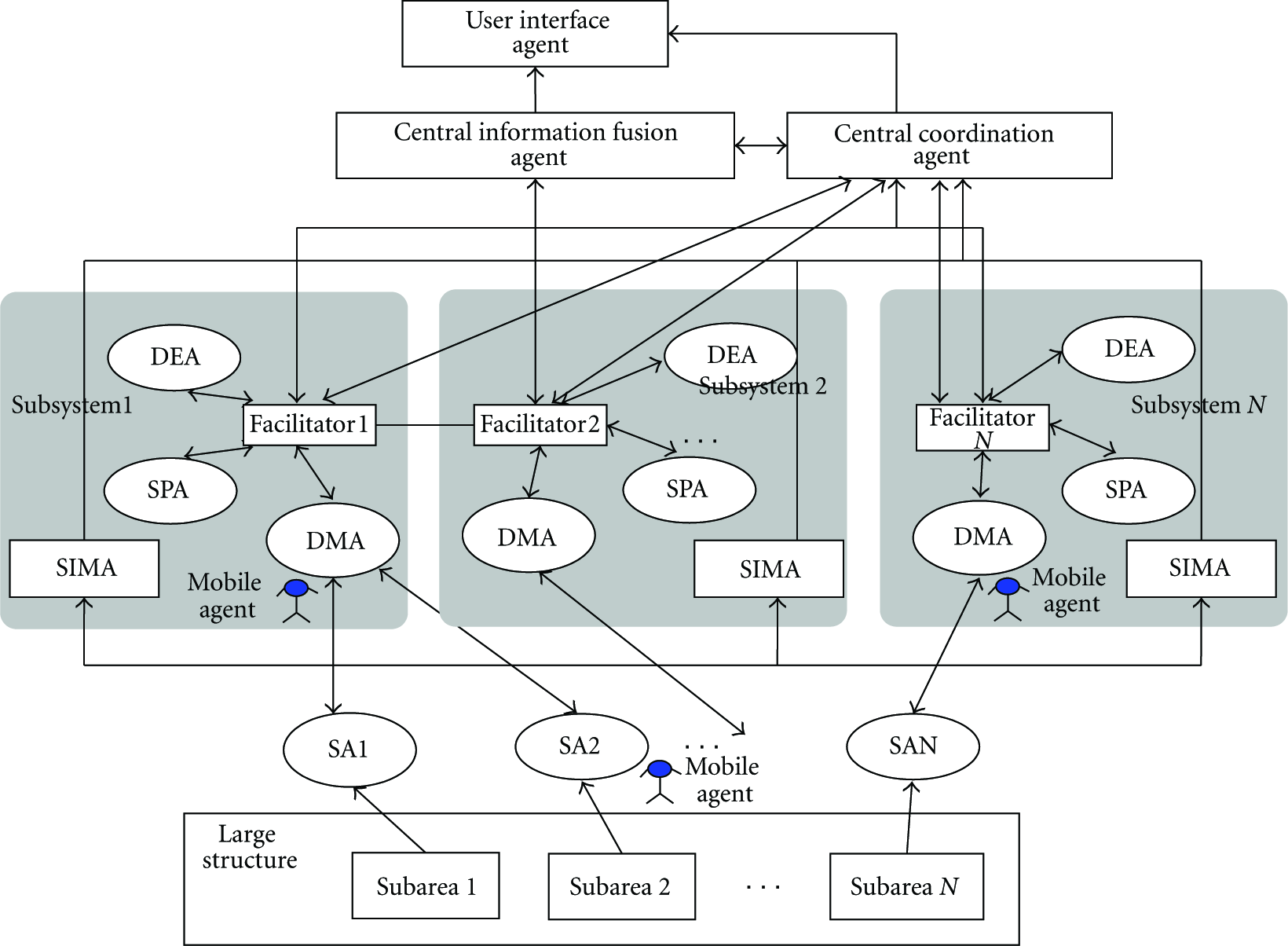
The software architecture of mobile multiagent system for WSN-SHM.
3. Evaluation of SHM Based on Mobile Multiagent System
In order to verify the effectiveness of mobile multiagent system for WSN-SHM, in this paper, a large aerospace aluminum plate structure is studied as the experimental object. The wireless sensor array is adopted to monitor two typical structure damages such as strain distribution change and joint failure.
3.1. System Setup
In Figure 3, it gives the plate structure and the sensor distribution diagram, and the photo of the structure and the wireless sensor node are shown in Figure 4. The plate structural material is the aerospace hard aluminum LY12, whose basic dimensions and thickness are 120 cm × 200 cm × 0.25 cm. Around the structure, there are 64 M6-bolts which are used to fix the plate with bracket, and the bolt space is 10 cm. The bracket is put on the ground vertically, supporting the aluminum structure. The structure is divided into eight subareas, each of which is 49 cm × 45 cm except its edge. PZT sensors are laid on the vertices of each subarea. In the 3rd subarea, FBG sensors are arranged, and four strain gauge sensors are correspondingly laid on the reverse side of the structure, and in other subareas, the strain gauge sensors are laid on the right side of the structure. The finite element model and experiment experience are followed for putting these strain gauge and PZT sensors on the structural stress concentration positions. In addition, each subarea is divided into nine regional units.
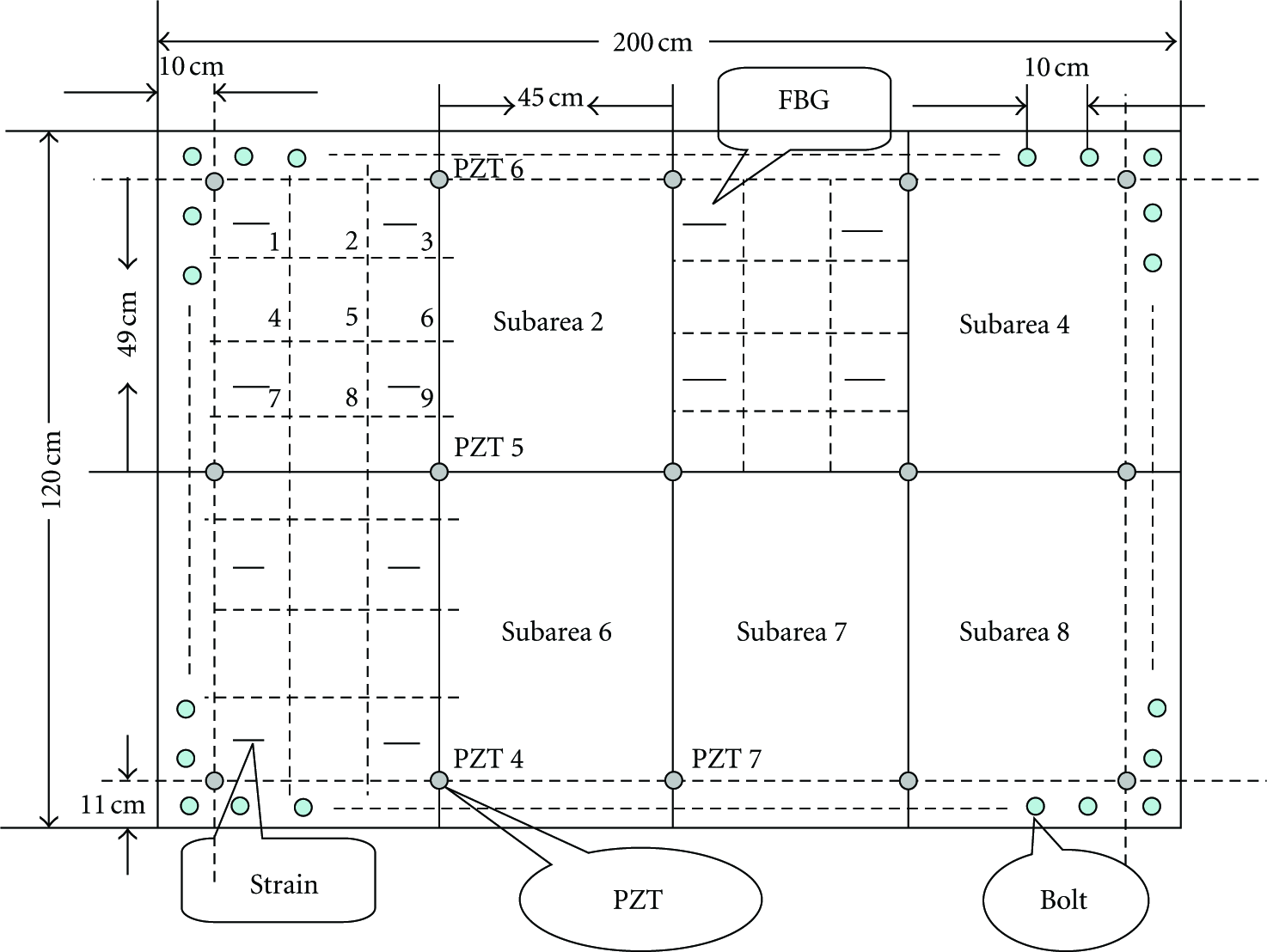
System setup.

The photo of the structure and WSN.
In the paper, the presented mobile multiagent system for WSN-SHM is described in detail for the strain distribution change and joint failure monitoring as follows. It should demonstrate the advantage: the system can migrate the signal processing or evaluation method to different sensor networks, allocate the monitoring tasks, process with the database distributed in the node, route and select the returned path autonomously, self-organize sensor network, return the result to the station management node with the node's collaboration, aggregate and fuse the distributed sensor information, and coordinate to estimate the strain distribution change and joint failure position.
3.2. Theory
Strain distribution change and joint failure are two types of damages in SHM, which can be identified by the pattern recognition technology. Their principle is as follows.
The structural strain distribution change generated by static load is monitored by the strain sensor network [2]. The sensor outputs of the monitored substructure form a pattern to represent its strain distribution. Once a concentrated load applies on different positions of the structure, its strain distribution changes correspondingly. As a result, the output mode of the sensors in the monitored subarea also changes. The pattern recognition method can be used to classify different patterns to decide different positions of the applied static load or strain distribution change. Generally, the minimum-distance classification is adopted for the static load localization. If the distance between the monitored strain pattern and a reference strain pattern in database is the minimum, the load position of the reference strain pattern is deemed to be the one of the monitored pattern.
The joint failure induced by bolt loosening is generally monitored by the active SHM method adopted [2]. The method is based on the structural vibration response and uses the piezoelectric sensor as the actuator or the sensor. For the large structure, the cycle-actuator multisensor scheme is adopted since the power of the actuator is finite, and numerous structure joint bolts and pattern overlapping exist. PZT sensors around the boundary act as actuators in turn. Each time the signals of two adjacent PZT sensors are sampled. Generally, a sine wave at a frequency is excited by PZT actuator to the structure, under which the vibration response of the structure is sensitive to the bolt loosening. The experiment proves the sensor signal varies before and after the bolt loosening [23]. Hence, the peak changes of the sensor signals are extracted to form the feature mode for pattern recognition. The neural network is often applied to identify the loosening bolt [23].
3.3. Wireless Sensor Network and Mobile Agent System
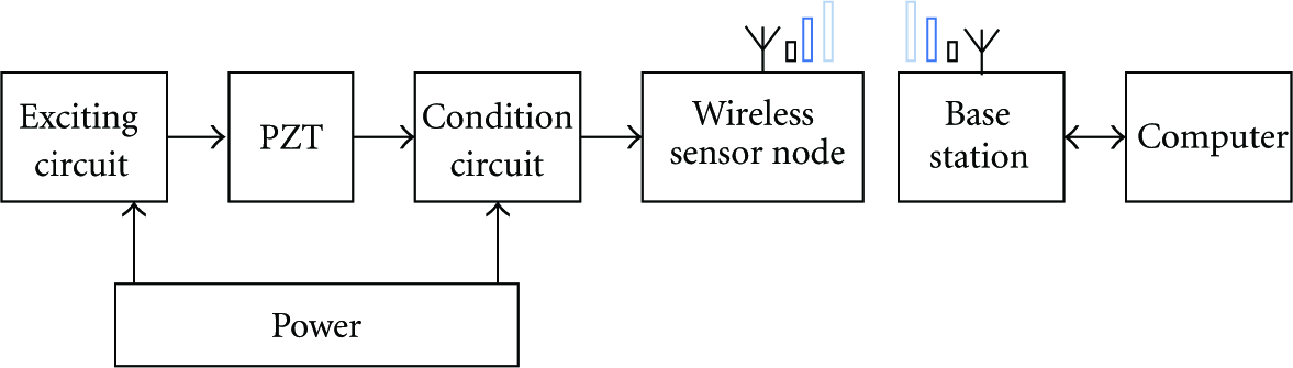
The entire hardware schematic diagram for the WSN-SHM system is shown in Figure 5. The entire system includes wireless strain sensor node and wireless PZT sensor node developed independently by the laboratory, stations management node, and central computer. For the system, the strain gauge sensor is connected to the wireless strain sensor node for strain measurement, and the signal of PZT sensor is obtained by the wireless PZT sensor node for joint failure active monitoring. These wireless sensor nodes communicate with each other by the wireless transmission based on ZigBee protocol. The stations management node communicates with the central computer by the Serial Port.

The schematic diagram for the wireless sensor system integration.
3.3.1. Agent System Development
In the multiagent system, all agents are implemented by software except SA which is implemented by the measurement hardware and software. The software is programmed with nesC language, LabVIEW 8.5, and MATLAB R2006a in the central computer.
In the software, there are data monitoring layer agents, data interpretation layer agents, damage diagnostic layer agents, and information layer agents. Each of the layers contains a number of agents performing different functions. The social ability and cooperation between the agents leads to the final damage estimation. The functionality and major composition principles of the agent within each layer are described below.
(1) Data Monitoring Layer Agents
Strain Sensing Agent (Strain SA)
The static strain change generated by the concentrated load applied to the plate is measured by the sensing agent.
Generally, the strain gauge is adopted to measure the strain distribution. The strain gauge sensor is the most usual sensor to monitor the strain, and it has cheap price and stable performance. It is connected to the wireless sensor node through the bridge circuit, and condition circuit as shown in Figure 6 [24]. Figure 7 gives the schematic circuit diagram for the 3 V high-precision power supply and conditioning the strain gauge sensor signal. Strain SA consists of four sensors in a subarea, a wireless sensor node, and the node's acquisition and communication program implemented by nesC language.
For the wireless strain sensor, the relationship between the output voltage change

The connection of the strain gauge and its WSN.
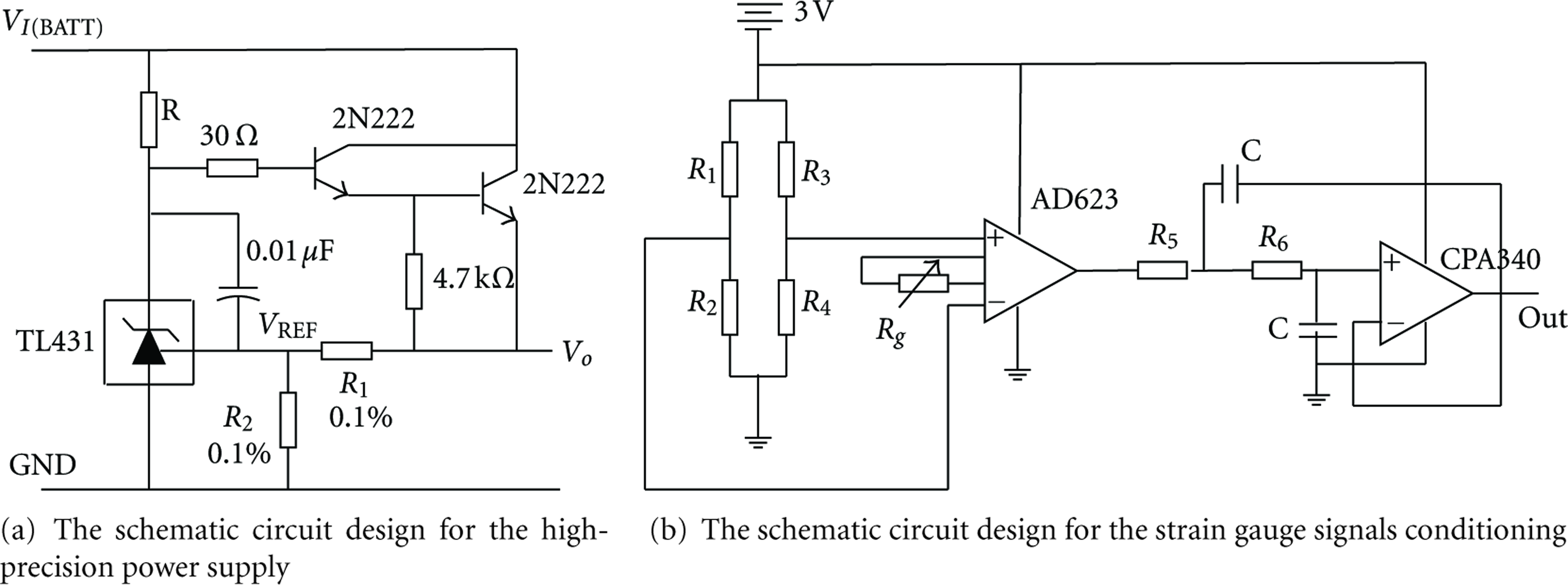
The schematic circuit diagram for conditioning the strain gauge sensor.
PZT Sensing Agent (PZT SA)
The agent is responsible for monitoring the joint failure using the cycle-actuator multisensor method.
Generally, PZT element is adopted to actuate or sense the structural dynamic strain response, and it is connected to the wireless sensor node as the actuator or sensor. The active monitoring for bolt loosening can be finished by the wireless PZT sensor node [28]. As shown in Figure 8, the node integrates sine wave generator module, data acquisition module, and condition module. Figure 9(a) shows the schematic circuit design for a sinusoidal signals actuator circuit, and Figure 9(b) shows the schematic circuit design for a PZT signal conditioning circuit in the evaluation system. In the assessment experiment, fifteen PZT elements are considered, in which twelve ones are used to monitor the joint failure around the boundary on the frame. PZT SA consists of a PZT sensor and a wireless sensor node connected, and the node's acquisition and communication program developed by nesC language.
For the wireless PZT sensor, the output of excitation circuit with the timer TCL555 is the sine wave with 100 kHz, whose amplitude is 5 V. The magnification times K of the two-stage amplifier OPA 340 circuit are tunable from 50 to 100. The TMS320F2812 DSP is a highly integrated low-power and high-performance 32-bit digital signal processor. Its sample frequency of the 12-bit analog-to-digital converter in the node's DSP is 10 MHz.
The connection of the PZT and its WSN.

The schematic circuit design for PZT actuator and signals conditioning.
District Monitor Agent (DMA)
The agent is in charge of managing strain SAs and PZT SAs. Each DMA supervises four neighboring strain SAs, which are in charge of monitoring Subarea 2, 3, 6, 7, and fifteen PZT SAs on the plate. It resides in SMN and is responsible for generating and transmitting MA and receiving the data from CN, and coordinates and delivers data and information between agents of each layer for damage evaluation. It is implemented by LabVIEW.
(2) Data Interpretation Layer Agents.
The layer agents have the LabVIEW work threads, and the communication protocol interaction thread, and their tasks are to extract the signal feature.
Static Load Signal Processing Agent (SL SPA)
The agent uses the moving average method for the signal of Strain SA.
Bolt Loosening Signal Processing Agent (BL SPA)
It extracts the peak value of the response from PZT SA.
(3) Damage Diagnostic Layer Agents.
The layer agents also consist of the work thread integrating with the MATLAB function, and the communication protocol interaction thread with LabVIEW. They begin the process of turning the data into information that is of greater use to the user. In addition, the agent in the layer uses the advanced intelligent system techniques coupled with codified knowledge problems and offers a prognosis.
Static Load Damage Evaluation Agent (SL DEA)
The agent uses k nearest neighbor (k-NN) classifier for the static load location identification. k-NN classifier is very simple and effective [29]. The k nearest neighbors of the unidentified test pattern is searched within a hypersphere of predefined radius in order to determine its true class, which is the most class in the k samples. If only one nearest neighbor is detected, k-NN is the minimum-distance classification.
Bolt Loosening Damage Evaluation Agent (BL DEA)
The agent implements the bolt loosening position identification for support vector machine (SVM) classifier [30]. The classifier is based on statistical learning theory, and it can obtain the good recognition rate derived from fewer training samples than the neural network classifier [31]. Kernel function is a key parameter for SVM, which includes linear, polynomial, Gaussian RBF, and sigmoid.
(4) Information layer agents
The layer agents also integrate with the work thread and the communication protocol interaction thread with LabVIEW. They are responsible for fusing and coordinating the bottom layer agent.
Facilitator Agent (FA)
Every subsystem should host a default FA. It manages the agent's ID and service name built with LabVIEW cluster array.
Sharing Information Management Agent (SIMA)
A default SIMA should host in every subsystem and manage all the agent's IDs and addresses in the subsystem. The agent stores the agent's ID and address built with LabVIEW cluster array, which is set to be shared variable and is able to start up and stop other agents.
Central Information Fusion Agent (CIFA)
The agent fuses different information from different local subsystems to obtain the most reliable and precise conclusion.
User Interface Agent (UIA)
The agent provides the information to the user and accepts the user's instruction. UIA is realized with LabVIEW control.
Central Coordination Agent (CCA)
The agent is responsible for coordinating the whole monitoring process. It collaborates DMA to generate and control MA with the algorithm and decides when to start the static load location process, when to deal with the joint bolt loosening and when to self-organize the sensor network.
MAS comprises a number of agents, which is to solve the complex problem not finished by a single agent and is the coordination network among agents. The coordination mechanism is the key issue in MAS research. In mobile multiagent system for WSN-SHM, the coordination principle is shown in Figure 10 for the static load and bolt loosening localization. Once CCA checks that there is PZT SA working at actuator status, wireless PZT sensor network is triggered to identify the joint failure. Otherwise, wireless strain network is activated to locate the static load. Since bolt loosening is an accumulated damage, the cycle monitoring is adopted, and the static load damage needs real-time monitoring. Hence, DMA periodically transmits MA to wireless PZT sensor network, drives the node to actuate the structure in turn, migrates from source to destination for obtaining the data and feature and publishes the feature vector to DMA for the damage evaluation. In the other most time, once the strain change crosses a threshold on the structure, DMA transmits MA to wireless strain sensor network, migrates from source to destination for acquiring the data and feature and identifying the damage location, and publishes the evaluation to DMA. The detailed principle and evaluation result are given as below.

The work principle of the whole wireless sensor system.
3.3.2. Collaborative Static Load Localization
As shown in Figure 11, subareas 2, 3, 6, and 7 are monitored by 4 sensor nodes composed of 16 strain gauges that form the sensor network. In this paper, a loading equipment is utilized to change the strain distribution in the plate. 70 N is chosen in the demonstration.

The scheme of the strain distribution change monitoring based on WSN.
The presented distributed wireless strain sensor network mode based on MA for strain distribution change monitoring is different from the traditional mode, and it need not to obtain the data from all the nodes, centralize to process, and finish the pattern matching as shown in Figures 12 and 13. The principle is given in detail as follows.
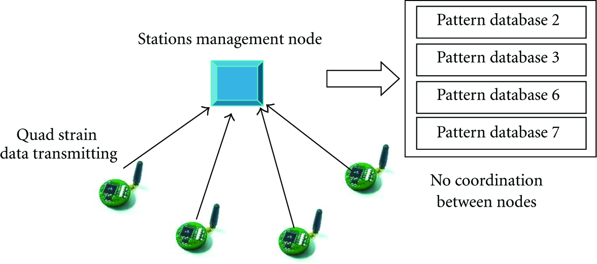
The traditional wireless strain sensor network monitoring mode.

The wireless strain sensor network monitoring mode based on MA.
Every time when Strain SA reads the data of four strain variation of its subarea, it stores them in the temporary base of the node. A standard pattern database is also established in the node, which is a fixed base. If Strain SA finds the maximum change between fixed base and temporary base exceeds 20 μ ε, DMA controls SMN to route MA with SL SPA and SL DEA to all the SNs to deal with the strain distribution change localization, in which the first migrated node is defined to be CH. The threshold 20 μ ε is set according to the finite element modeling analysis based on MSC, Patran/Nastran software, and practical loading experiments. The multiagent implementation process for collaborative strain distribution change localization includes following steps. Figure 14 shows the workflow of the multiagent implementation process for the strain distribution change localization.
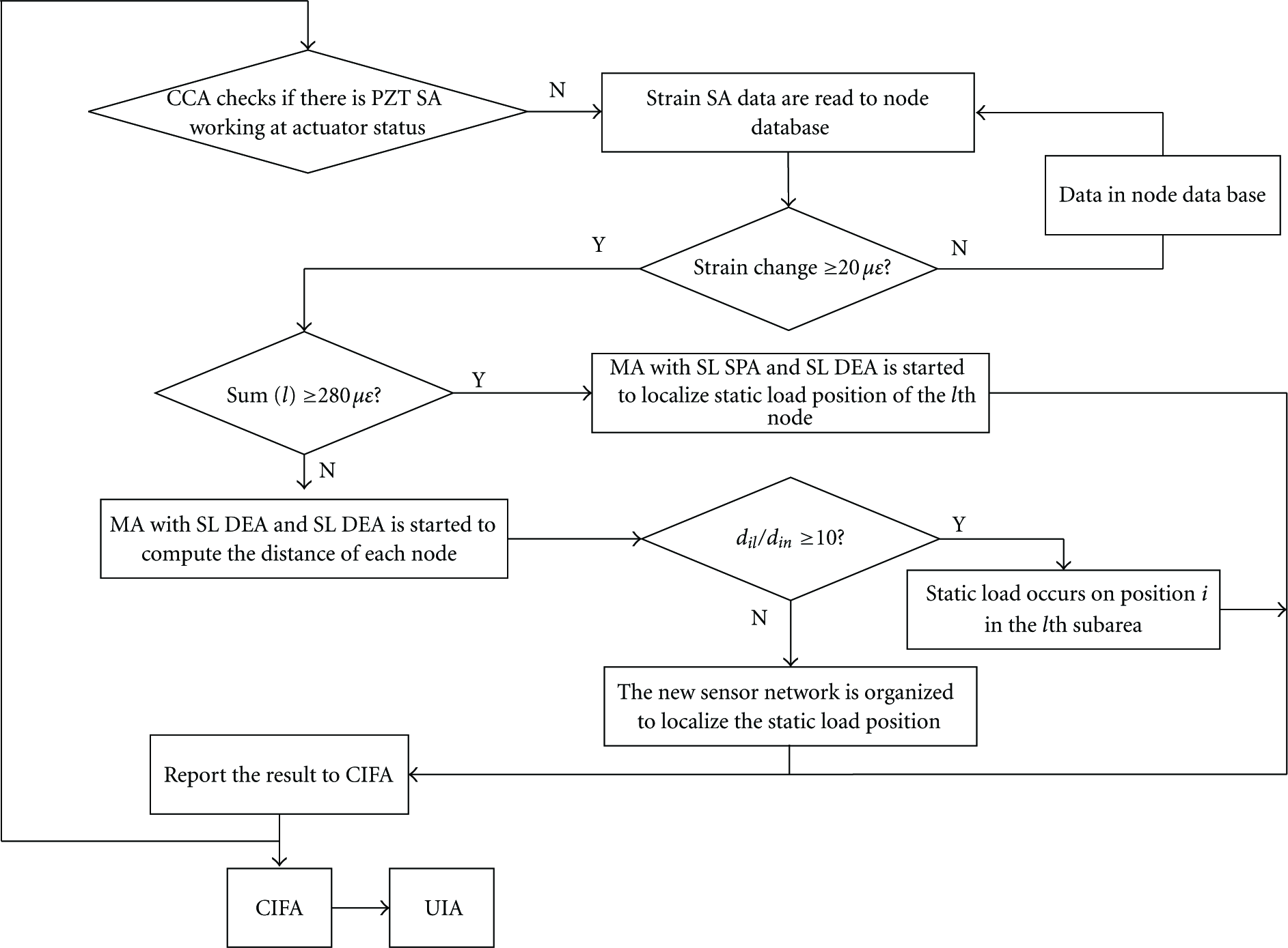
The workflow of the multiagent implementation for the strain distribution change localization.
Step 1
In every subsystem, DMA sends an MA with the strain computation and judgment algorithm to each node for the initial damage location evaluation. Firstly, MA calculates the sum of four absolute values of the strain change (
Step 2
If there is a sum value exceeding 280 μ ε for some node, DMA sends MA2 with SL SPA and SL DEA to the node according to its ID received for damage location evaluation. The final location result is transmitted to DMA, and MA2 departs.
Step 3
If there is no sum value exceeding 280 μ ε for all the nodes, MA3 is sent by DMA. MA3 with SL SPA and SL DEA is started to compute nine Euclidean distances in each node, and transmitting the minimal distance
Step 4
If the ratio of two minimal Euclidean distances is less than 10, DMA sends MA4 to the node. MA4 deems that neither of the subareas develops successful localization, and the static load position may be on the boundary between two adjacent areas. Hence, the agent organizes the sensor network, and aggregates and transmits the data of the organized four sensors to DMA. DMA tells DEA in its subsystem to identify the load location. The utilized fixed base is in SIMA of its subsystem.
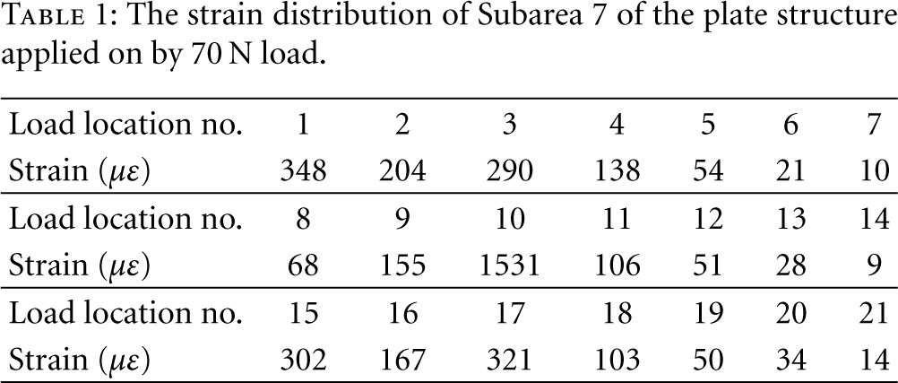
In the experiment, twenty-one possible load positions are numbered in two subareas as shown in Figure 11. The length of the moving average is 70 for the strain gauge. For Strain SA, the strain changes of the four strain sensors are combined to be a feature vector with four dimensions. For each position, six samples are measured to train parameters of the classifiers. When 70 N load occurs in the twenty-one positions, the absolute sum of four sensors’ strain of Strain SA 7 changes as shown in Table 1. The collected signal waveforms of Strain SA 2 are shown in Figure 15. Next, 1-NN DEA with Euclidean distance is utilized to classify the calculated features of the strain distribution change. The classification accuracy is evaluated using a ratio of the number of the samples classified correctly to the total sample. When the static load appears at the boundary between Subareas 3 and 7 as shown in Figure 11, the corresponding strain variation in the four subsystems belongs to Step (3) above. MA finds the
The strain distribution of Subarea 7 of the plate structure applied on by 70 N load.
The strain distribution change location identification results.


Sensor strain signal of subarea 2 of plate structure applied on by 70 N load.
3.3.3. Joint Failure Active Coordination Monitoring
The cycle-actuator two-sensor scheme is adopted for joint failure monitoring. In Figure 16, through multiagent cooperation, the wireless sensor network nodes connected by PZT elements around the boundary are self-organized to act as the actuator in turn. The PZT node as actuator and its two adjacent PZT nodes as sensors constitute a cluster, and the actuator node is defined as CH of the cluster.

The scheme of the joint failure monitoring based on wireless PZT sensor node.
Every time when PZT SA reads the strain data of the local site of its subarea, it stores them in the temporary base of the node. Since the bolt loosening identification needs to fuse all the features from the whole area, a standard pattern database is only established in SIMA of each subsystem, which is implemented in the central computer connected with SMN resided by its DMA. Hence, its standard pattern database is also established in the computer. The multiagent implementation process for collaborative joint failure localization includes following steps.
Step 1
According to CCA's coordination request, DMA self-organizes the PZT sensor network and orderly routes MA1 to twelve nodes on the plate boundary as shown in Figure 17. Firstly, MA1 starts PZT SA1 (its sensor name is PZT1) as the first actuator. Then, its neighboring two PZT SAs acquire the data, number and store them in the temporary base of the node. Thirdly, MA1 migrates to the next node for finishing the scheme of the one-actuator two-sensor until it traverses to all the nodes. At last, MA1 is back to DMA and departs.

The wireless PZT sensor network mode based on MA for the joint failure monitoring.
Step 2
DMA routes MA2 with BL SPA to these nodes on the border in turn for extracting the peak feature of its resident data in each node. Meanwhile, MA2 transmits the two features and their ID to DMA. Finally, MA2 returns SMN and departs.
Step 3
DMA waits and receives the features from all the nodes. Then, the agent sorts these features according to their ID and publishes the feature vector to BL DEA by Facilitator agent for the pattern location. The final result is sent to UIA by CIFA.
In the experiment of the joint failure, each time only one bolt is full loosening. The loosening of bolt 3, 5, 8, 9, 23, 27, 39, 50, and 54 are studied as shown in Figure 16. MA controls twelve PZT SA circularly and periodically to excite and sense the structure strain signal. Figure 18 gives the signal of PZT sensor 1 as actuator and PZT sensor 2 as sensor before and after bolt loosening of Bolt 5, and it gives that the signal of PZT sensor 1 as actuator and PZT sensor 4 as sensor before and after bolt loosening of Bolt 9. As shown in the figure, the bolt loosening causes the acquired strain signal to change since bolt loosening could cause the change of the prestress distribution in the structure and the bolt loosening can partly affect the scattering Lamb wave coupled with bolt. The number of sampled data is 600, and the measured time is 0.06 ms. Twenty-four acquired signal peak changes of the twelve sensors on the plate border for PZT SA are combined to be a feature vector as shown in Tables 3 and 4. Since PZT element as actuator in turn is PZT1, 2, 3, 6, 9, 12, 15, 14, 13, 10, 7, 4, the first and the second features in the feature vector are the peaks of two acquired signals of PZT 1 as the actuator and PZT2, 4 as the sensors, and are defined as 1-2/1-4. Hence, the third and the fourth features are defined as 2-1/2-3, and so forth. For chosen bolts, twelve samples are measured to train parameters of the classifiers. Table 5 gives the test accuracy of the SVM classifier agents, in which the kernel function
The feature vector before Bolt 5 loosening.

The feature vector after Bolt 5 loosening.

The part identification result of bolt loosening.


PZT sensor signal change before and after bolt loosening bolts.
4. Conclusion
In order to build an efficient, robust, reliable, and autonomous large structural health monitoring system for wireless sensor network, a mobile multiagent system is applied to integrate distributed wireless sensor network. The proposed method is illustrated through a large dimension aerospace aluminum structure monitoring experiment in which strain distribution and joint failure are monitored by different sensors. The result shows that the method can significantly improve the monitoring performance for the large-scale structure. In the future work, the validation work of mobile multiagent system and wireless sensor network on the large-scale composite material structure will be considered.
Footnotes
Acknowledgments
This work was supported by European Union 7th Framework Program international cooperation project (Grant no. FP7-PEOPLE-2010-IRSES-269202), Natural Science Foundation of China (Grants nos. 60772072, 50830201, and 10872217), the Fundamental Research Funds for the Central Universities, and Funding of Jiangsu Innovation Program for Graduate Education (Grant no. CX10B_097Z).