
Abstract
In a large-scale wireless sensor network, a topology is needed to gather state-based data from sensor network and efficiently aggregate the data given the requirements of balanced load, minimal energy consumption, and prolonged network lifetime. In this study, we proposed a ring-based hierarchical clustering scheme (RHC) consisting of four phases: predeployment, parent-child relationship building, deployment, and member join phases. Two node types are distributed throughout the network: cluster head nodes (type 1 node) and general sensor nodes (type 2 node). The type 1 node has better battery life, software capability, and hardware features than the type 2 node; therefore, the type 1 node is a better cluster head than type 2 node. Due to our IP naming rules and type 1 nodes as cluster heads, public key cryptography, such as RSA (Rivest, Shamir, Adleman), or ECC (Elliptic Curve Cryptosystem), is easily implanted to our system to strengthen our security. The sink node is the only certification authority in our system, but n level cluster heads can be extended to n level certification authorities if needed, where n is maximum number of level.
1. Introduction
In recent years, wireless sensor networks have been studied in many different applications, including environmental monitoring, battlefield surveillance, and other domains. In each of these applications, global state-based data are collected by all sensors and periodically transmitted to a sink. Given their compactness and extremely low cost, wireless sensor nodes are often drained by the limited source.
Fortunately, most nearby sensors report very similar ambient parameters to base station; hence, these data can be aggregated and/or compressed before being relayed to base station. In addition to improving accuracy, data aggregation also substantially reduces energy requirements due to reduced network communication overhead.
Two optimization metrics are often used to prolong network lifetime. One minimizes total energy consumption, and the other maximizes the lifetime of the network node with the shortest lifetime because a node failure can cause network partitioning and inaccuracies in sensing data.
To minimize energy consumption, nodes are partitioned into “clusters,” each with a cluster head belonging to a type 1 node and several member nodes belonging to type 2 nodes. The type 1 node has better battery life, software capability, and hardware features than the type 2 node. The network structure is also organized heterogeneously and hierarchically such that cluster head nodes are further classified into different levels, which achieves substantial energy savings, and employing the ring-based way of predeployment.
The cluster head nodes in the proposed scheme are deployed according to a predeployment process before deploying general sensor nodes. The predeployment is followed by a parent-child relationship building process in which each cluster head node follows a specific naming rule as described in later subsection. The deployment of type 2 nodes is also followed by a member join process.
The remainder of this paper is organized as follows. Section 2 presents related work. The proposed scheme is proposed in Section 3. Section 4 evaluates the performance of the proposed scheme. Section 5 concludes the study.
2. Related Work
Due to the technical difficulty and energy constraints on recharging sensor nodes, several approaches have been proposed to save energy and prolong network lifetime. Data aggregation makes use of the property that different local regions may report the same aggregated values to the information center.
Tiny aggregation (TAG) [1] processes perform aggregation by discarding irrelevant data and combining and compacting relevant data. Directed diffusion [2] proposes a new data-centric dissemination paradigm which organizes data according to attribute-value pairs. When a user requests data, it sends the interest for the data. Data matching the interest is then transmitted back to the requestor. Hence, energy savings can be achieved by selecting good paths and by implementing data aggregation.
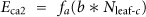
Also, in order to prolong network lifetime, LEACH [3] uses a clustering technique by rotating the role of cluster heads for each time period; therefore, the total number of nodes remaining active exceeds that when using static clustering. Furthermore, Bhardwaj et al. [4] provided an upper bound on the lifetime of sensor networks to minimize energy dissipation by using an optimum number of relay nodes. The minimum energy consumed by transmitting from one sensor to next is characteristic distance, denoted by
Mhatre and Rosenberg [5] proposed two node types, one with more power for cluster head and the other for cluster member. Two communication modes were proposed (single hop mode and multiple hop mode both from sensors to cluster head), and the optimum numbers of cluster heads under single and multiple hop modes were determined supposed that from all clusters to base station need only one hop. Bandyopadhyay and Coyle [6] proposed a distributed algorithm for organizing sensors into a cluster of hierarchies to minimize the system energy consumed from general sensors to cluster heads and finally to sink node. Chen et al. [7] proposed EPAS and later hEPAS, which conserve energy by organizing cluster heads into a hierarchy in which each sensor node follows a two-phase pickup rule to be a cluster head in order to maintain the expected optimal cluster number at each level. In [8–11], the clustering technique is also used as an efficient method of improving network lifetime and is a primary metric for evaluating network performance.
There are several papers related to heterogeneous sensor networks except [5]. In [12], Matrouk and Landfeldt propose a routing protocol, based on temperature to which energy is transformed, by using heat conduction formulas. The protocol transforms the expected lifetime of each node into an equivalent temperature, and then finds the hottest path from source node to sink in order to equalize the residual energy throughout the heterogeneous wireless sensor networks.
In hostile environment, solid and efficient synchronization scheme needs to be designed to defend against different kind of attacks. In [13], Du et al. present a secure and efficient time synchronization scheme for heterogeneous sensor networks (HSNs). The authors also propose a secure and efficient routing protocol for HSNs—Two Tier Secure Routing (TTSR) [14]. In [15] Du et al. present an efficient routing protocol based on the chessboard clustering scheme, which balances node energy consumption and significantly increases network lifetime.
In [16] Yang and Cardei propose a delay-constrained energy-efficient routing in heterogeneous wireless sensor networks in which the scheme consists of static sensor nodes, mobile and static super-nodes. Each source sensor, with data to be transmitted, selects the best relay supernode in its routing table so as to satisfy the delay requirements. Message is transmitted from source sensor to relay supernode by sensor-to-sensor way, and from relay node to sink by supernode-to-supernode way.
Since data aggregation is one key approach to extending lifetime of sensor networks, a number of paper are published. Adaptive aggregate tree [17] is proposed to dynamically transform the structure of the routing tree to improve the efficiency of data aggregation. The author of [18] introduces multiple-input turbo code to implement jointly source coding channel coding and data aggregation. Due to the character of multiple input sequences and implementation of partial interleaving, both memory size and access requirements are reduced.
The proposed data aggregation scheme in [19] employs an elliptic curve cryptography-based homomorphic encryption algorithm to offer data integrity and confidentiality along with hierarchical aggregation. In [20] Wu et al. present a Delay-Constrained Optimal Data Aggregation framework that considers the unique feature of traffic patterns and information processing at application nodes for energy saving. In [21] Ozdemir and Xiao investigate the relationship between security and data integrity process in wireless sensor networks. A taxonomy data aggregation protocol is given by surveying the current “state-of-the-art” work in this area.
A scheduling called Distributed Power Scheduling [22], a medium access control protocol which supports data aggregation, is proposed. It integrates data aggregation into power-mode scheduling in the MAC layer and effectively reduced packet delay. In [23] Solis and Obraczka explores in-network aggregation as a power-efficient mechanism for collecting data in wireless sensor networks. The authors evaluate the performance of different in-network aggregation algorithms in terms of tradeoffs between energy efficiency, data accuracy and freshness.
In [24] Wu et al. propose a secure aggregation tree (SAT) to detect and prevent cheating. Through the method which is without persistent cryptographic operations when all sensor nodes are working honestly, the energy and CPU source can be saved. In [25] Li et al. propose an efficient algorithm to solve the maximum lifetime many-to-one data gathering with aggregation (MLMTODA) problem. In [26] Cheng and Yin propose a new balanced aggregation tree (BAT) for tree construction that can be used for aggregate data and nonaggregate data.
In [27] Kafetzoglou and Papavassiliou propose a framework which combines two different energy-saving methods from two different layers, application layer and Medium Access Control (MAC), by appropriately adopting sleeping mechanisms. In [28] Zou et al. introduce the concept of flow loss multiplier, which is dependent on the spatial relationship among sensed areas, to express the impact of data aggregation on the conveyed traffic. The approach based on in-network data aggregation at the First Hop away from each sensor data source, followed by flow-based routing of the resulting traffic, is proposed to extend the lifetime of wireless sensor networks (WSNs). In [29] the authors propose a routing protocol called the Clustering-Base Expanding Ring Routing Protocol (CBERRP) which mainly focuses on the network layer while integrating factors from other layers to gain the preferred performance. In [30] Stanford and Tongngam propose the approximation algorithm for the problem of maximizing sensor networks lifetime with data aggregation by applying Garg-Könemann algorithm.
In [31] the authors propose an idea of energy management by employing relay nodes in a wireless sensor network. The locations and data generation rates of sensor are predetermined by the application's sensor placement algorithm whose problem is a nonlinear programming. The algorithm determines the optimal locations of relay nodes which dissipate optimal energy so as to satisfy desired lifetime with minimum total energy of the entire network.
In [32] the authors superpose two types of clustered architectures of wireless sensor networks to yield ultra hierarchical structures. A secure aggregation protocol for sensor networks is derived from this architecture. The authors significantly improve the SAPC [33]. The clustered WSN of Sun et al. [34] is used as the cluster of level 1. A variant of the method for defining virtual architectures in [35] is developed to produce clusters of level 2 and higher. Base station is the only one which can be trusted, and it does not need to fulfill any aggregation process.
Ultra hierarchical cluster formation consists of three phases. In phase 1, the BS first generates a chain of key
Data aggregation also comprises three phases. The cluster heads do not achieve the aggregation but all the other members of their clusters do so as to promote the probability of overall honesty. In phase 1, BS generates two private key K1 for all non-CH nodes and K2 for all CH nodes. In phase 2, data aggregation is formed and passed from low level to higher level following eight steps recursively until phase 3: reception of data by the BS. During phase 2, each member except CH1(cluster head of level 1) sends to other members of its cluster with data encrypted by
Compared to scheme in [32], our proposed scheme RHC has two node types which are distributed throughout the network. The type 1 node has better battery life, software capability, and hardware features than the type 2 node does; therefore, the type 1 node is a better cluster head than type 2 node. Predeploying type 1 nodes at roughly certain positions can save many type 1 nodes to be distributed over the whole area. Due to their better battery life and aggregator roles, the whole system lifetime of network can also be extended. Besides, members of clusters which do not need to carry our aggregation can save a large amount of energy consumption of type 2 nodes. In [32] two types nodes with same battery life but different roles: CHs through election, members of clusters.
Once deployment process completes, the self-organization process is initiated by parent-child relationship building process and then member join process. Due to our hierarchical structure which is well suitable for public key cryptography, the use of public key cryptography can ease many problems during the data delivery processes, for example, authentication, integrity, and nonrepudiation. Public key infrastructure can also easily be applied to future new public key cryptography. Any node in our system only needs two keys (a public key and a private key); therefore, the total keys of our system are less than those in [32].
In our proposed scheme, it has the following characteristics:
Heterogeneity, multilayer hierarchical structure, IP naming way, public key infrastructure.
3. Proposed Scheme
As noted above, the proposed network employs two types of nodes: cluster head nodes and general sensor nodes. In the one-level data aggregator mechanism (only one hop is required from the farthest cluster head to sink), the sink is located at the center of the region (red circle), as Figure 1 shows. For being simple and easy to recognize, all sensor nodes in this structure are partitioned into seven clusters represented by black circles (actually each cluster range is larger than black circle), and each cluster has a cluster head.

One-level hierarchy.
The cluster range (radius), which is indicated by the region between the black circle and its concentric blue circle, is large enough to cover all type 2 nodes for all clusters. Each cluster head radius can be approximated as radius of the region divided by square root of cluster number as proposed in [37], which is larger than the radius of the black circle and less than the radius of blue concentric circle, and can enough cover all its own type 2 nodes. Like many other simulation modes, transmission power is assumedly adjusted to satisfy all transmission distances between nodes. The blue circle represents the communication range between two neighboring cluster heads. The cluster head collects data from their member sensors then aggregates, compresses, and sends the aggregated data to the sink. Therefore, the sink and each cluster head have a parent-child relationship which is determined by the parent-child relationship building process. The sink and each cluster head have several general sensors. The general sensors are randomly and uniformly distributed such that each cluster has approximately the same cluster members. Therefore, the energy consumption of the type 2 node is evenly consumed and thus minimized. This approach requires the six cluster heads to be deployed to respective around positions. The radius of the region is assumed to be R; therefore, the six cluster heads are located around
In Figure 2, for being simple and easy to recognize, each cluster is also represented by a black circle. In fact, the range of a cluster is larger than the black circle, and all the clusters cover the area of whole deployment region. In the two-level hierarchical structure, the first level has six clusters, and the second level has twelve (because the distance from level 2 cluster head to sink is twice that from level 1 cluster head to sink); that is, the sensor nodes are partitioned into nineteen clusters (including the sink). The six first-level cluster heads are located around

Two-level hierarchy.
Generally, in L-level hierarchical structure (L hops are required from the farthest cluster head to sink), the level i cluster head number is
After the predeployment and deployment process, the parent-child relationship building process and the member join process are performed, respectively. Those processes employ an IP naming rule, which is described in the later subsection.
3.1. Predeployment Process
This study assumes that the network has only one sink located at the center of the circle region although the scheme can also be applied to other region shapes with many sinks. During this period, the cluster head nodes (type 1 nodes) are roughly deployed at certain positions ring by ring surrounding the sink, depending on how many levels are distributed. Figures 1 and 2 are examples of a one-level and a two-level hierarchy, respectively.
3.2. Deployment Process
During this period, all type 2 sensor nodes are randomly and uniformly distributed over the region. The nodes join their cluster head nodes after receiving cluster head signals based on the member join mechanism described in the next subsection.
3.3. Parent-Child Relationship Building and Member Join Process
In the parent-child building process, the sink node initiates the process by issuing a signal and then asking other nearby nodes (type 1 nodes) to become its subroot child nodes. If the value of received signal strength (RSS) received by nearby type 1 node is within the acceptable threshold range depending on distance between the two neighboring level, then the node becomes a subroot child node of the sink. After becoming a subroot child node or the descendants of the sink, each node has been assigned by the sink or the descendants of the sink can ask nearby unassigned nodes to become their subroot child nodes. If a type 1 node receives two or more signals requesting it to become a subroot child node, then the lowest level cluster head (the one nearest the sink) within RSS signal range is selected as its parent node; otherwise, the cluster head with the strongest and within RSS signal range becomes its parent node.
In the member join process, if a general node receives only one signal from a nearby cluster head, it joins this cluster as a member. If a general node receives two or more than two signals from nearby cluster heads simultaneously, it then becomes a member of cluster head with the strongest signal. After this process, the topology structure is complete.
3.4. IP Naming (Assignment) Rule
There are three reserved ranges in IP4 version:
10.0.0.0–10.255.255.255/8 (16,777,216 hosts) 172.16.0.0–172.31.255.255/12 (1,048,576 hosts) 192.168.0.0–192.168.255.255/16 (65,536 hosts).
We use first range as our addresses which are from 10.0.0.0 to 10.255.255.255. The first 8 bits of IP are always 00001010. Hence, the last 24 bits can be used for IP naming.
A simple but powerful naming rule is used to establish relations among all nodes in the parent-child relationship building and member join phases. Each node IP is named as follows. The last 24 bits of 32-bit IP are divided into eleven fields, My_IP(1)~My_IP(11). My_IP(1) is 1 bit long with value 0 or 1, and My_IP(2) is 3 bit long with values ranging from 0 to 7; My_IP(3)~My_IP(10) are 2 bits long with values ranging from 0 to 3; My_IP(11) is 4 bits long with values ranging from 0 to 15. If My_IP(11) is not 0, then the node must be a leaf node. Each node in the network is named by its parent (except the sink, which names by itself), and according to the named IP, each node can identify its level and its parent and child if any. The three different network roles, assuming only one sink, are as follows:
root node (sink): type 1 node, subroot node (cluster head): type 1 node: all cluster heads except sink are subroot nodes, which are type 1 nodes, leaf node (sensor node): type 2 node.
Root Node (Sink)
The root node initiates the parent-child relationship building process. We assume that a type 1 node is adopted as a root node and placed at the center of the region. A value 1 is selected and assigned to My_IP(1), and the remaining fields are set to zero. Hence, every field except My_IP(1) is zero. In the proposed scheme the root node (sink) has six subroot child nodes (from My_IP(2), which has a maximum of seven and reserves 0 for root-node), which can be controlled and recorded by the root node. This feature is precious because, in a stationary multihop network, signal strength of a node is optimal when it has six neighboring nodes [39]. An example of a root node is the following. A node with an IP address
Subroot Node (Type 1 Node)
A subroot node can become a child of another subroot node or a child of the sink. Further details can be found in [40]. For simplicity, only the condition in which a subroot node joins the sink and becomes its child node is described here. When a sink (e.g., node S) sends a signal to ask an unsigned type 1 node (e.g., node B) to become a child of the sink, S first assigns the IP of node B to that of node S and then adds an unused value (1 to 6) to the first zero field from left side of the IP of B. Once a node becomes a subroot node, it then signals other unsigned type 1 nodes to join and become its subroot child nodes. The sink can have a maximum of six subroot child nodes. For instance, the node with the IP address
Leaf Node (Type 2 Node)
When a subroot node requests a type 2 node to become a member of the subroot node, the subroot node first assigns the IP of the type 2 node to its own IP and adds an unused value to second zero My_IP field (first zero My_IP field must be zero) from left side to My_IP(11) to obtain the final IP of this leaf child node. For instance, the node with the IP address
Having built all the relationships among all nodes, each leaf node knows who its parent is and should send sensed data to its parent (cluster head), and each subroot node aggregates and compresses received data and then sends to its parent. Finally all sensed data will be received by the sink. Wireless sensor network with IP naming rule has several advantages such as free role switching, fault tolerance, load balancing, and secure data transmission which are described in Section 3.6.
3.5. Energy Consumption of an L-Level Hierarchy
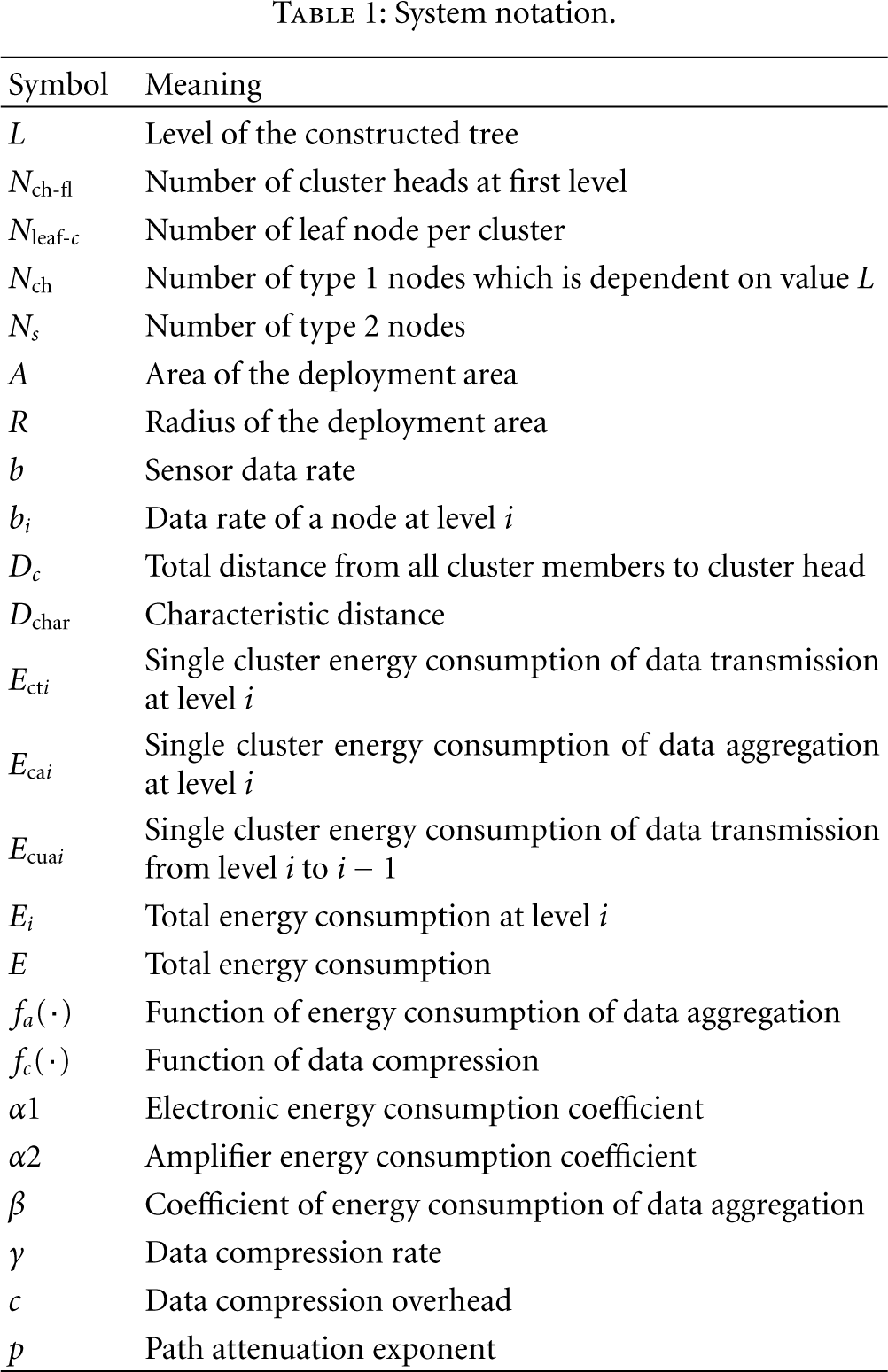
This subsection describes how total energy consumption of an L-level hierarchy structure in the proposed scenario is calculated according to transmission, aggregation, and compression. Table 1 lists the system notations used for measurement. The sink is assumed to be located at the center of the circular region A with radius R.
System notation.
One-Level Hierarchy
An example of a one-level (L = 1) hierarchy is considered first. In a one-level hierarchy, the number of cluster heads, 
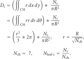
If 
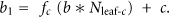
Since the first level cluster number is 
Two-Level Hierarchy
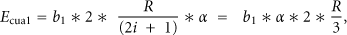
For a two-level (L = 2) hierarchy, let 


The total energy consumption at level 2 is

Let 


L-Level Hierarchy
Let 


3.6. Discussion
The proposed scheme has several advantages as follows.
(1) No Switch for Role
Type 1 nodes are cluster heads responsible for data aggregation, compression, and transmission to their upper layer (parent node); type 2 nodes are solely responsible for collecting and transferring sensed data to the cluster head. By avoiding cluster pickup and role switching, these node roles substantially reduce computation time.
(2) Fault Tolerance
In accordance with the naming rule, a subroot node can have at most three subroot child nodes. Generally, a subroot node allows only two subroot child nodes to become its child nodes. If a sibling subroot node malfunctions and then breaks the links with the sibling subroot child nodes, the subroot node can still assign one free IP address to one of the subroot child nodes of the sibling. As a result, fault tolerance is promoted. Additionally, by performing the parent-child building relationship and member join process, each general sensor node may receive two or three cluster head signals. Once its cluster head is out of function, a sensor node can try to join another nearby type 1 node.
(3) Load Balancing
By predeploying type 1 nodes and deploying type 2 nodes over the region, the burden of energy dissipation is evenly distributed amongst all sensor nodes. The upper layer cluster head nodes gradually become heavier than the lower layer cluster head. The lack of abrupt changes enables excellent load balancing.
(4) Secure Data Transmission
We use public key cryptography to strengthen our security. Our hierarchical structure is well suitable for public key cryptography. The use of public key cryptography can ease many problems during the data delivery processes, for instance, authentication, integrity, and nonrepudiation. After member join process, each node has an IP and knows its children if any, and also father IPs. Sink acts as trusted third party certificate authority T, whose public key (PKT) is known to all valid nodes. A node L receives a certificate from T as follows:


4. Simulation Result
Table 2 shows the defined system parameters, which are referenced from [3, 5, 7]. The simulation is performed using java language. Ten thousand type 2 sensor nodes are uniformly distributed over a circular region with a 1000-meter radius. The aggregation function is
System parameters.

Our proposed scheme has considered using two types of sensor node and also building multiple level hierarchies of cluster heads to reduce energy consumption. In order to compare with the other schemes, we also propose a uniform deployment single level scheme (USL) which also has two types of sensor node but from each cluster head to sink needs only one hop.
Figure 3 shows the number of cluster heads for different levels in the proposed scheme. Clearly, more type 1 nodes in the system enable more type 1 levels. In Figures 4 and 5, for RHC (proposed scheme) scheme the values of x-axis represent number of level while for USL scheme each value
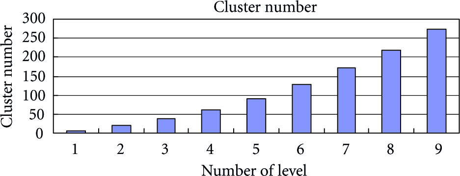
Relationship between number of level and cluster number.

Total energy consumption for two different schemes.

Maximum energy consumption of type 1 node for two different schemes.
Now we would like to investigate the ratio of lifetime and cost under different level for first type 1 node failure metric. Let 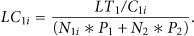

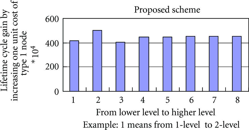
Lifetime cycle gain by increasing one unit cost of type 1 node.
5. Conclusion
This study proposed a ring-based scheme using two node types to organize a ring-based efficient hierarchical topology with many levels to optimize energy utilization. Type 1 nodes were first predeployed in approximate positions calculated by our formula. Type 2 nodes were then randomly and uniformly deployed over the circular region with the sink located at center of the area. The relationships between the sensor nodes were determined by the parent-child building and member join process. The three network roles are root-node, subroot node, and leaf node. Several simulations using the same system parameters but different levels demonstrate that the proposed scheme can achieve substantial energy savings. Due to our IP naming rules, public key cryptography is easily implanted to our system to strengthen our security. The sink node is the only certification authority in our system, and data can be sent to any node safely by the public key cryptosystem.