
Abstract
Idleness has to be carefully exploited in wireless sensor networks (WSNs) to save power and to accumulate the energy possibly harvested from the environment. State-of-the-art microcontroller units provide a wide range of ultra-low-power inactive modes with sub-millisecond wakeup time that can be effectively used for this purpose. At the same time they are equipped with 16-bit RISC architectures clocked at tens of MHz, which make them powerful enough to run a Java-compatible virtual machine (VM). This makes it possible to bring the benefits of a virtual runtime environment into power-constrained embedded systems. VMs, however, risk to impair the effectiveness of dynamic power management as they are seen as always-active processes by the scheduler of the operating system in spite of the idleness of the threads running on top of them. Avoiding to keep sensor nodes busy when they could be idle is mandatory for the energetic sustainability of WSNs. While most of the tasks of a sensor node are inherently event-driven, the functioning of its hardware-software components is not, so that they require to be redesigned in order to exploit idleness. This paper presents VirtualSense, an open-hardware open-source ultra-low-power reactive wireless sensor module featuring a Java-compatible VM.
1. Introduction
The lifetime of a wireless sensor network (WSN) depends on the capability of its nodes to adapt to time-varying workload conditions by turning off unused components and by dynamically tuning the power-performance tradeoff of the used ones. Dynamic power management (DPM) is a wide research field which has brought, on one hand, to the design of power manageable components featuring multiple low-power state and, on the other hand, to the development of advanced DPM strategies to exploit them. DPM is a constrained optimization aimed at meeting the performance requirements imposed by the application at a minimum cost in terms of energy. The main power-saving opportunities come from idle periods, which allow the power manager to take advantage of ultra-low-power inactive modes. Idleness is particularly important in wireless sensor nodes, which spend most of their time waiting for external events or for monitoring requests, and which are often equipped with energy-harvesting modules which promise to grant them an unlimited lifetime [1] as long as their average power consumption is lower than the average harvested power.
State-of-the-art ultra-low-power micro-controller units (MCUs) provide a suitable support to the DPM needs of WSNs, since they feature a wide range of active and inactive power states while also providing enough memory and computational resources to run a virtual machine (VM) on top of a tiny operating system (OS). Virtualization adds to the simplicity and portability of applications for WSNs at the cost of increasing the distance between hardware and software, which might impair the effectiveness of DPM both for the limited control of the underlying hardware offered by the virtual runtime environment, and for the limited visibility of the actual activity offered by the VM. In fact, the VM is usually viewed by the scheduler of the embedded OS as a process which is always active in spite of the possible idleness of its threads. Two solutions have been proposed to address these issues. The first one is provided by bare-metal VMs, which runs directly on top of the MCU without any OS [2–4], at the cost of loosing portability. The second one is provided by full-fledged software stacks specifically designed for power manageable sensor nodes in order to make it possible to take DPM decisions directly from the runtime environment and to grant to the OS scheduler full visibility of the idleness of the virtual tasks.
In spite of the availability of ultra-low-power modes provided by the MCU, the effectiveness of DPM risks to be impaired by the paradigm adopted for inter node communication. Although a sensor node is primarily designed to sense a physical quantity and to send a message to the sink to report the measured value, most of the nodes in the network act as routers to relay other nodes’ messages towards the sink. While all other activities can be either scheduled or triggered by external interrupts, receiving a message is an asynchronous event which needs to be carefully handled.
This paper presents VirtualSense, an open-hardware open-source platform for the development of ultra-low-power reactive wireless sensor modules featuring a Java-compatible VM. VirtualSense is based on Texas Instruments’ MSP430F5418a MCU and on modified versions of Contiki OS [5] and Darjeeling VM [6]. VirtualSense makes directly available from the Java runtime environment all the low-power modes of the underlying MCU. Moreover, it features an event-driven communication library which makes it possible for a Java thread to react to incoming messages without keeping the MCU busy while waiting.
This work provides a comprehensive overview and a detailed description of the results achieved by the VirtualSense project [7] by presenting the VirtualSense platform, by providing a detailed power-state model for it, and by presenting the results of extensive measurements conducted on a working prototype.
1.1. Related Work
Since 1998, the family of UC Berkeley motes, derived from the Smart Dust and COTS Dust projects, has been a landmark in scientific research on WSNs [8, 9]. In particular the first prototype, called WeC, produced in 1998, was based upon an Atmel AT90LS8553 MCU clocked at 4 MHz and equipped with 512 B of RAM. Based on WeC mote, in 1999 a commercial platform called Rene was produced by Crossbow. Starting from Rene mote, in 2001 Crossbow developed one of the most popular wireless sensor mote called Mica. WeC, Rene, and Mica motes shared the same architecture and the same RFM TR100 radio transceiver (on the 916.5 MHz frequency band), but Mica used the new Atmel 128L MCU equipped with 4 KB of RAM. The Rene project then evolved in several well-known platforms including Mica2, Mica2Dot, and MicaZ. Mica family motes were equipped with different radio transceivers ranging from the Chipcon CC1000, working in the 900 MHz frequency band, for the Mica2 motes to the Texas Instruments CC2420, working in the 2.4 GHz frequency band, installed on the MicaZ mote. In 2005 UC Berkeley developed another popular sensor platform called Telos [10]. Telos was the first mote designed around the extremely low-power Texas Instruments MSP430 MCU family providing low-power modes with a consumption of a few μW. In particular, Telos mote was equipped with the Texas Instruments MSP430F1611 with 10 KB of RAM running at 8 MHz in order to minimize power consumption while increasing computational performance. As its predecessors, Telos used the Texas Instruments CC2420 radio transceiver for network communication.
In the last decade a number of wireless sensor nodes have been developed using several MCUs and Radio transceivers ranging from 16 to 32 bit platforms. In particular, in the 16 bit domain we can mention the BTNode [11] developed in 2003 by the Swiss Federal Institute of Technology, the TinyNode [12] developed in 2006 by the École Polytechnique Fédérale de Lausanne (EPFL), and Iris developed in 2006 by Memsic corporation [13]. In the 32 bit domain the most representative motes are Open-Wise [14] from the University of Colima, Opal [15] developed by Autonomous Systems Laboratory of Australia in 2011, iMote [16] and iMote2 [17] from Intel developed in 2003–2006, and XYZ mote developed by UC Berkeley in 2005 [18].
The key features of the motes are summarized in Table 1, which also reports the features of the VirtualSense mote presented in this paper.
Main features of existing motes.

Figure 1 provides a graphical representation of the power-performance tradeoff offered by the motes listed in Table 1. Each architecture is represented as a point in a log-log Cartesian plane where performance and power are reported in the x and y axes, respectively. Performance is expressed in terms of computational resources, computed as the product between MCU clock frequency (in MHz) and RAM size (in KB). Consumption is expressed by the average between the power consumption of the deepest sleep state with self-wakeup capabilities, and the consumption of the mote in receiving mode, weighted according to a 2% duty cycle. Power values for VirtualSense are taken from measurements (see Section 6), while all other data are taken from literature. In spite of the arbitrariness of the metrics adopted in Figure 1, they are effective to point out the differences between the existing motes and to evaluate their suitability to run a virtual machine. In particular, the vertical dotted line represents a computational resource threshold corresponding to a 10 MHz clock frequency and 10 KB of RAM, which can be regarded as minimum requisites to run a virtual machine on top of a mote. The black dot in the plot represents the positioning of VirtualSense, which provides a performance close to that of 32 bit architectures with an average power consumption lower than 2 mW.

Motes comparison.
1.2. Organization
The rest of the paper is organized as follows. Section 2 provides a minimum background on power manageable MCUs and on the software stack adopted for the development of VirtualSense. Section 3 presents the HW-SW platform of VirtualSense, outlining the main solutions adopted to address the issues raised by the interaction between the VM and the OS running on top of an ultra-low-power MCU. Section 4 introduces an event-driven communication library which enables the development of high-level communication protocols compatible with DPM. Section 5 outlines the power-state model of VirtualSense, which makes directly available from the Java runtime environment one active state and 7 low-power modes. Section 6 reports the results of extensive measurements conducted in order to characterize the power-state model of the sensor module and to evaluate its energy efficiency. Section 7 concludes the paper.
2. Background
This section provides an overview of the most relevant features of the three main components adopted for the development of VirtualSense, namely: a power manageable MCU, the Contiki OS, and the Darjeeling VM. Moreover, it introduces a power-state diagram to be used to describe the combined behavior of the three components.
2.1. Power Manageable MCU
Ultra-low-power MCUs exploit idleness to switch off power-consuming components in order to save energy. Although different MCUs can differ in the number and in the names of the low-power states they provide, for our purposes we consider a generic MCU to be represented by a power state machine with four categories of power states, called Active, Standby, Sleep, and Hibernation, characterized by the components which are turned off and by the consequent tradeoff between power consumption and wakeup time.
In Active mode the CPU is running and the unit is able to execute tasks without incurring any delay. In Standby mode the CPU is not powered, but the clock system is running and the unit is able to self wakeup by means of timer interrupts. In Sleep mode both the CPU and the clock system are turned off and the unit wakes up only upon external interrupts. In Hibernation even the memory system is turned off, so that there is no data retention. Wakeup can be triggered only by external interrupts and it entails a complete reboot of the CPU.
2.2. Contiki OS
Contiki is an open source real-time OS specifically designed for sensor networks and networked embedded systems [5]. The key features of Contiki OS are: portability, multitasking, memory efficiency, and event-driven organization. Each process in Contiki can schedule its own wakeup and go to sleep without loosing the capability of reacting to external events.
The basic power management mechanism in Contiki exploits the Standby state of the MCU by setting a timer interrupt (namely,
The inherent event-driven structure of Contiki provides a mean for minimizing the energy overhead caused by periodic wakeup. This is done by making the interrupt handler aware of the next time at which a process has to be resumed in order to go back to sleep without invoking the scheduler in case of premature wakeup.
2.3. Darjeeling VM
Darjeeling is a VM designed for extremely limited devices, specifically targeting wireless sensor networks [6]. Its main advantage stems from the capability of supporting a substantial subset of the Java libraries while running on 8-bit and 16-bit MCUs with at least 10 kbytes of RAM. The size of the bytecode is significantly reduced by means of an offline tool, called infuser, which transforms the Java bytecode into a custom bytecode and performs static linking of groups of classes. It is also worth mentioning that the Darjeeling VM provides a garbage collector and supports multithreading.
The VM executes on Contiki as a process which runs together with the OS protothreads implementing the NETSTACK communication protocol. The VM scheduler implements a round-robin policy in which each thread is allowed to execute for upto a fixed number of bytecodes before releasing the CPU. Whenever a thread is suspended, the VM waits for the next timer interrupt (possibly yielding resources) before resuming the execution of the next running thread.
2.4. Power State Diagram
Figure 2 shows the power-state diagram of a system running Contiki OS and Darjeeling VM on top of an MCU which provides the four power states introduced in Section 2.1. The Active mode is split into several states to represent the macrosteps required at wakeup to resume the execution of a task on the runtime virtual environment. Dashed arcs represent external interrupts, while solid arcs represent self-events. According to the definition of the low-power states, self-wakeup is enabled only from Standby, while external interrupts are required to wake up from Sleep and Hibernation. It is also worth noticing that a complete boot is required when exiting from Hibernation, while data retention allows execution to resume directly when exiting from Standby and Sleep modes. Transitions represented on the right-hand side of the graph denote the possibility of entering low-power states directly from a code segment and resuming execution from the same point at wakeup at any level of the software stack.

Power-state diagram of a generic power manageable MCU running the Darjeeling VM on top of Contiki OS.
According to the behavior described in Section 2.2, Contiki exploits the Standby state whenever all its running processes are waiting for scheduled timers or external events, but in order to keep control of the elapsed time it sets a periodic timer interrupt which wakes up the CPU every 10 ms. Upon wakeup the interrupt handler evaluates if there are running processes which need to resume execution. If this is the case the control is passed to the scheduler, otherwise the CPU is turned off again soon. As mentioned in Section 2.3, the Darjeeling VM running on Contiki is a process which needs to resume at each timer interrupt in order to check for the status of its threads. If there are no threads ready to resume, the process is suspended until next timer interrupt.
Labels a, b, and c in Figure 2 denote the transitions taken upon a timer interrupt in case of: (a) VM with no tasks to resume, (b) system with no processes to resume, and (c) virtual task to be resumed. Case (c) is the only one which makes the CPU worth to be woken up, while cases (a) and (b) are nothing but an overhead to be periodically paid while in Standby.
Figure 3(A) provides a simplified version of the power state diagram where (a) and (b) are represented as self-loops of the Standby state, while the overhead of the boot is implicitly associated with the wakeup transition from Hibernation, rather than being explicitly represented by the transient states of Figure 2. On the other hand, Standby mode is split into three different states in Figure 3(A) to stress the difference between pure Standby without periodic wakeup, and intermittent Standby with type (a) or type (b) timer interrupts.

Abstract representations of the state diagram of Figure 2 obtained by: (A) implicitly representing transient states as arcs with nonnull transition time and energy (B), removing periodic self-loops, and accounting for the corresponding cost into the power consumption of the corresponding states.
A further abstraction is provided in Figure 3(B), where self loops (a) and (b) have disappeared and their power overhead has been directly accounted for in the average power consumption of the corresponding standby states. Since such an overhead depends on the period of the timer interrupt (denoted by T), power states Standby.a and Standby.b represent families of power states, the average power consumption of which depends on the value of T. Because of the default settings of Contiki for the target MCU and of the interaction with the Darjeeling VM, the only low power state which is actually exploited is Standby.a with
3. VirtualSense Platform
VirtualSense is an open-source open-hardware project. This section outlines both the hardware software solutions adopted in the design of VirtualSense in order to make it possible to fully exploit the power states of Figure 3(B), while running applications on top of the virtual machine.
3.1. Hardware Architecture
VirtualSense is made of ultra-low-power off-the-shelf components in order to keep the overall consumption compatible with state-of-the-art energy harvesters and to enable the fabrication of low-cost motes.
Figure 4 shows the functional block diagram representing the hardware architecture. The core is an MCU belonging to the Texas Instrument MSP430F54xxa family [19]. It communicates through

Functional block diagram of the VirtualSense hardware platform.
A FTDI FT232R chip provides USB 2.0 communication capabilities and power supply to the sensor node, while a JTAG interface enables on-lab node programming [24]. Finally, 3 ADC channels are used to sample data from sensors. For testing purposes, the prototype was equipped with three representative sensors, namely: a BH1620FVC light sensor [25], an LM19 temperature sensor [26], and an HIH5030 humidity sensor [27].
3.2. Avoiding Periodic Wakeup
Periodic wakeup from Standby is used in the reference architecture outlined in Section 2 to maintain time awareness. The
In principle, periodic wakeup could be avoided in a power-managed system as long as an oracle exists to wake up the system right in time to execute useful tasks. The scheduler of the OS has the capability of acting as an omniscient oracle for the self-events scheduled by its processes. Similarly, the scheduler of the VM can act as an oracle for the self-events scheduled by its threads. In the reference architecture, however, neither the OS nor the VM exploits these prediction capabilities, ultimately impairing the energy efficiency of Standby mode. Two changes were made to overcome this limitation.
First, the scheduler of the Darjeeling VM was modified in order to take the time of the next scheduled task (as returned by function
A second change was implemented in Contiki to make it able to dynamically adjust the
The only drawback of slowing down the timer interrupt is the loss of accuracy in the perceived arrival time of external interrupts. In fact, although the MCU is able to react to asynchronous external interrupts regardless of the timer when in Standby mode, timer interrupts are required to update the system clock. This problem will be addressed in Section 3.4.
3.3. Hibernation
The main problem with Hibernation is the lack of data retention, which requires the heap of the VM to be saved in flash and restored at wakeup together with a few external variables, including the base address of the heap. In order to allow hibernation to be possibly triggered by a high-level task running on a thread, the context of the running thread has to be saved in the heap without waiting for a context switch. Moreover, a flag has to be added to the
It is worth noticing that the OS is not hibernated, so that it is rebooted at wakeup and the clock needs to be restored in order to make it coherent with the timers of the scheduled self events. Timing issues are discussed in the next subsection.
3.4. Dealing with Time
The low-power states described so far pose timing issues which get worse when moving from Standby to Hibernation. In pure Standby mode, in fact, the timer interrupt is used only to implement right-in-time wakeup, so that it does not provide any information about the actual time at which external interrupts occur. In Sleep mode, the clock system is switched off, so that the MCU is unable to schedule its own wakeup, which can be triggered only by external events which do not provide any information about the time elapsed while the MCU was sleeping. Finally, in Hibernation the RAM is switched off and the OS is rebooted at wakeup, so that even the time at which hibernation was triggered is lost unless it is stored in flash and restored at wakeup.
All these issues can be addressed by exploiting the external RTC available on the VirtualSense platform. The RTC can be used by the MCU both to schedule wakeup calls from the deepest low-power states, and to update the system clock at wakeup. It is worth mentioning that no RTC is required if the MCU is used only to implement bare reactive applications, such as sensor nodes used either to count external events or to give the alarm when specific conditions are detected.
4. Virtual Network Stack
Communication across the radio channel is handled by the
It is worth noticing that power consumption of Standby.a(T) is several orders of magnitude higher than that of Sleep and Hibernation. Moreover, the wakeup time is larger than 10 ms, so that the MCU would stay always active while waiting for a message unless a longer timer interrupt was set in the modified stack. The minimum timer interrupt which could allow the exploitation of Standby mode is
The event-driven communication library presented in next section solves this issue by enabling the exploitation of all the low-power states of a power-manageable virtual sensor node waiting for incoming messages.
4.1. VirtualSense Communication
The software architecture of the proposed communication framework is shown in Figure 5, where arrows are used to represent the event chain triggered by the reception of an incoming packet. The figure points out the interactions between user-level and system-level execution flows, as well as those between Contiki processes (namely,

VirtualSense software architecture.
While waiting for an incoming packet all the processes are blocked and they do not consume any computational resource. When a packet is received by the radio device, the
It is worth noticing that, in order to make it possible for the
The event chain described so far is general enough to enable the implementation of any kind of communication protocol either within the
Sending a packet is much simpler than receiving it: the
In the following we outline the three packages developed to extend the Darjeeling Java libraries in order to support the event chains described above: (i)

VirtualSense communication class diagram. Public methods are denoted means “+,”l while protected and private methods are denoted by “#”and “−,”respectively.
4.2. Radio Package
The
Unicast and broadcast send methods make use of the Contiki
4.3. Network Package
The
The
Methods
4.4. Concurrent Package
The
4.5. MAC Layer
VirtualSense communication relies on Contiki MAC layer [28], which provides a simple duty cycling mechanism to reduce the power consumption of the radio module by keeping it turned off for most of the time without impairing the capability of the node to take part in network communication. This is done by periodically waking up the radio module to sense the channel and wait for incoming packets. In order to relax synchronization constraints, unicast packets are iteratively sent until an ack is received, while broadcast packets are repeatedly sent in a time window large enough to guarantee that they are sensed and received by all the nodes in range.
The current version of Contiki does not support the new Texas Instruments CC2520 radio module, but it provides a driver for its predecessor: the TI CC2420. In order to make it possible for VirtualSense to use the CC2520 (which provides higher energy efficiency, frame filtering capabilities, and low-power reception modes) a specific device driver needed to be developed starting from that of CC2420. The new driver not only exploits all the features of the new radio module, but it also exploits a deeper low-power mode (namely, LPM2 instead of LPM1) for duty-cycling. Since in LPM2 the radio module has no data retention, the driver needs to take care of the reconfiguration of the module at each wakeup.
Although a thorough description of the ContikiMAC protocol is beyond the scope of this paper, extensive experiments will be reported in Section 6.1.3 in order to allow the reader to evaluate the power consumption of the radio module in the different phases of communication.
5. VirtualSense Power-State Model
The changes outlined in the previous subsections enable the full exploitation of the low-power states depicted in Figure 2 and introduce three additional states which correspond to the Standby, Sleep, and Hibernation modes with external RTC. The new low-power states are denoted by suffix “.t” in Figure 7(A). With respect to the corresponding original states the new ones not only provide more accurate timing information, but they also grant the MCU the capability of scheduling its own wakeup from Sleep and Hibernation. This possibility, denoted by the solid arcs exiting from states Sleep.t and Hibernation.t, allows the MCU to exploit the corresponding low power modes even if there are future self events scheduled by the running processes/threads.

Figure 7(B) provides a simplified version of the same power-state model, in which state Standby.a has been removed, and Standby.b has been renamed “Standby.tick”. The two changes have been made to point out that the modified software stack of VirtualSense avoids the MCU to go through the time-consuming self-loop denoted by (a) in Figure 2, and that parameter T used to trigger periodic wakeups from Standby corresponds to the time resolution of the OS. This is the power-state model adopted hereafter to characterize the platform.
To make it possible to develop advanced DPM algorithms while working on top of the virtual machine, a
The frequency and voltage scaling capabilities of the new Texas Instruments MSP430x5xx MCU family [29] have been also exported on top of the Darjeeling VM (by implementing both the native methods and the drivers for Contiki OS) to allow applications to change at runtime the MUC operating frequency. Whenever the operating frequency is changed, the supply voltage of the core is automatically adjusted by the Contiki driver to the minimum voltage compatible with that frequency.
The degrees of freedom provided by the high-level support to frequency scaling add a dimension to the power-state model of VirtualSense which is not represented in Figure 7(B) for the sake of simplicity.
A thorough characterization of the power-state model is provided in next Section, while the effects of voltage and frequency scaling are discussed in Section 6.1.2.
6. Measurements and Results
Extensive experiments were conducted to characterize the power-state model of VirtualSense and to evaluate its energy efficiency in representative situations. To this purpose, synthetic benchmarks were developed and run on top of a VirtualSense mote instrumented in order to make it possible to measure not only the overall consumption of the platform, but also the current drawn by the MCU and by the radio module. This was done by inserting 10
Data acquisition and measurements were done by means of a National Instruments NI-DAQmx PCI-6251 16 channels data acquisition board connected to a BNC-2120-shielded connector block [30, 31]. In addition, a National Instruments PXI-4071 digital multimeter was used to characterize the low-power states with sensitivity down to 1 pA [32].
During the experiments the mote under test was powered by means of an NGMO2 Rohde & Schwarz dual-channel power supply serially connected with the PXI-4071 configured as amperometer [33] to capture the total current drawn by the mote.
6.1. Characterization
In order to enable a thorough understanding of the contributions to the overall power consumption of the VirtualSense mote, three sets of experiments were performed: the first set was run to characterize the power state model of Figure 7(B) in fixed working conditions (namely,
6.1.1. Power Modes
The characterization of the power modes of the VirtualSense mote was performed by sampling at 100,000 Hz the waveform of the supply current while running a simple benchmark forcing transitions to each low-power mode. The current waveforms were then analyzed in order to single-out the peaks corresponding to shut-down and wakeup transitions. A representative current waveform is reported in the lin-log plot of Figure 8 as provided by the NI-DAQmx. In order to improve the accuracy of the results, the power consumption of the ultra-low-power modes was further measured with the PXI-4071 multimeter while the exact timing of the transitions was determined by instrumenting the benchmarks.

Supply current waveform of the VirtualSense mote obtained by forcing transitions to low-power modes.
Since the low-power mode denoted by Standby.tick(T) in the power state model of Figure 7(B) represents a family of power states the power consumption of which depends on the length of the ticks used to trigger periodic wakeups, an additional experiment was performed to characterize such a dependence, which is represented in Figure 9. Each point was obtained by setting the tick period (T), by keeping the node in standby for 60 seconds, and by computing the average power consumption. A fitting curve of type
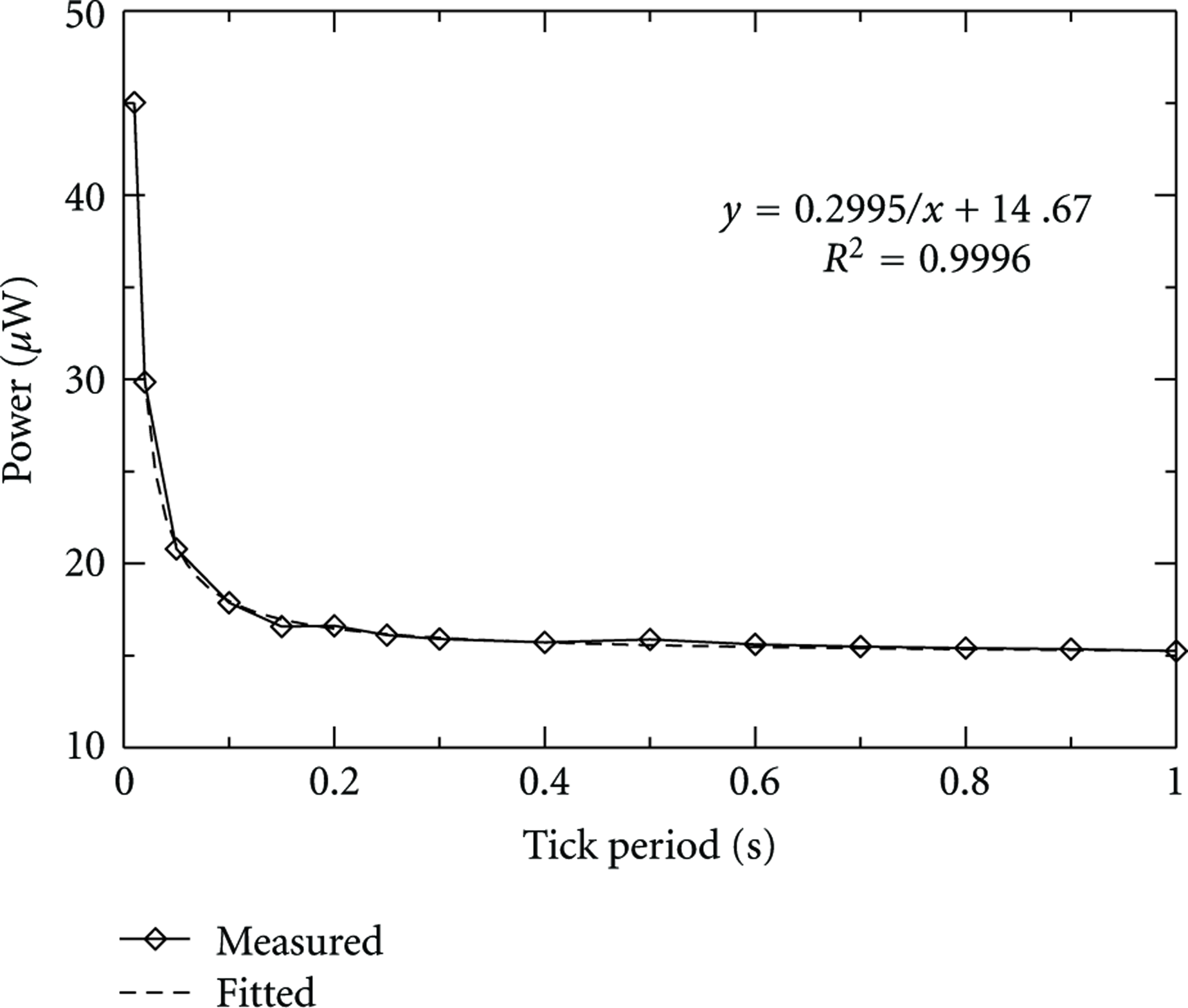
Power consumption of Standby.tick(T) as a function of tick period T.
Table 2 reports the results obtained with the MCU powered at 3 V and clocked at 16 MHz, using 4 Kbyte for the heap of the VM. For each inactive state 5 parameters are reported: power consumption (Power), wakeup time (WUt), wakeup energy (WUe), shut-down time (SDt), and shut-down energy (SDe). Since the proposed architecture makes power management available on top of the VM, wakeup costs include the time and energy spent in all the steps required to resume the execution of the running thread. Missing entries in Table 2 refer to transition times lower than 0.01 ms and transition energies lower than 0.01μJ. The power consumption of state Standby.tick is expressed as a function of the
Characterization of the power-state model of a virtualsense mote with the MCU powered at 3 V and clocked at 16 MHz with a 4 kbyte VM heap.

It is worth noticing that there is a difference between the average power consumption of the three Standby states. For instance, with an
Using for comparison the same MCU running standard releases of Contiki OS and Darjeeling VM, the only inactive state available would have been Standby.a (as defined in Section 2.4) with
6.1.2. MCU Voltage and Frequency Scaling
Figure 10 shows the current consumption of the VirtualSense platform running a benchmark which executes at different clock frequencies a CPU intensive task consisting of 10,000 integer summations. The benchmark makes use of the native methods for DPM provided by VirtualSense to set the clock frequency of the core, execute the task, and go to sleep. The current waveform plotted in Figure 10 clearly shows the power saving obtained by reducing the clock frequency from 25 MHz to 8 MHz, and the corresponding increase in the execution time of the task.

Power consumption of the mote while the MCU is executing a CPU-intensive task at different clock frequencies.
The overall energy spent to execute the task is plotted in Figure 11 as a function of the MCU frequency. The dashed curve (labeled “

Computational energy versus MCU frequency.
Two additional curves are shown in Figure 11 for comparison. The dotted line (labeled “
6.1.3. Communication Energy
As mentioned in Section 4.5, VirtualSense makes use of Contiki MAC layer for communication. Figures 12 and 13 report the current waveforms of the MCU (solid lines) and of the radio module (dotted lines) in the different phases of communication.
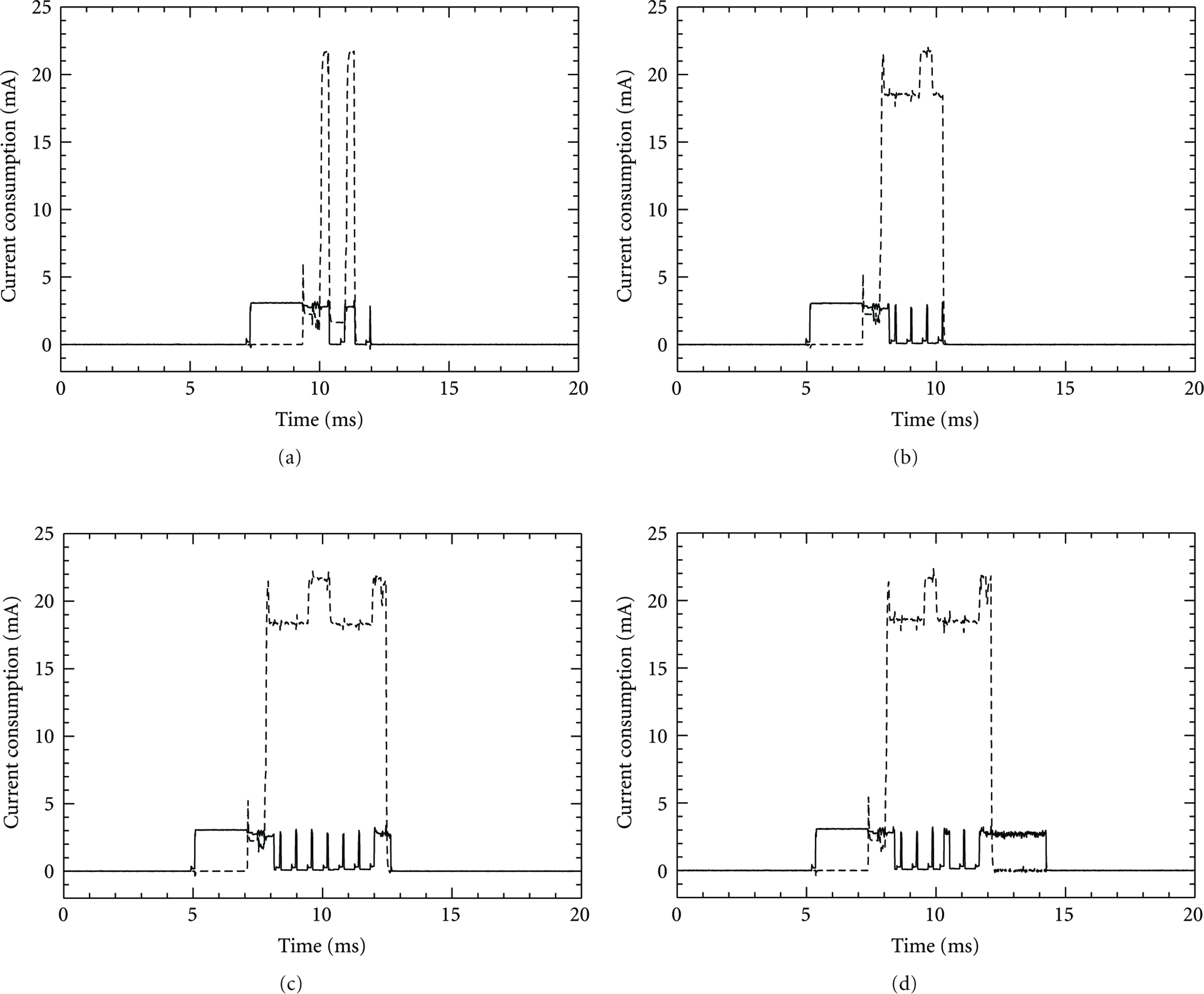
Power consumption of MCU (solid line) and radio transceiver (dotted line) during: (a) channel clear assessment, (b) frame filtering, (c) broadcast reception, and (d) broadcast reception and processing.

Power consumption of MCU (solid line) and radio transceiver (dotted line) during: (a) unicast send and (b) broadcast send.
Figure 12(a) refers to the case of a channel clear assessment (CCA) without incoming packets. The MCU is woken up by a timer interrupt to run the interrupt handler which wakes up and reconfigures the radio module (the corresponding software overhead is apparent in the plot). According to the ContikiMAC protocol, the radio module then performs the CCA twice, with 1 ms interval in which it goes in LPM1 (rather than in LPM2) in order to avoid further reconfigurations. If nothing is sensed on the channel, the CC2520 goes back to LPM2.
Figure 12(b) refers to the case of a filtered packet. In this case the packet is sensed by the CCA, but it is directly discarded by the frame filter of the radio module upon decoding of the MAC header. This is the case of a unicast packet addressed to another node.
Figure 12(c) refers to the case of a packet which is properly received and then discarded at the MAC layer after having passed the frame filter of the radio module. This may happen, for instance, if the packet is corrupted, or if it was already received. Without frame filtering, this would also happen whenever a nonintended message was received. Hence, the difference in time between cases (c) and (b) provides a measure of the energy efficiency of frame filtering.
Finally, Figure 12(d) shows the additional software overhead which is incurred when the packet is passed up to the application through the protocol stack.
According to the duty cycling mechanism of ContikiMAC, each packet has to be sent multiple times waiting either for the acknowledge sent back by the receiver (in case of unicast transmission) or for a timeout (in case of broadcast packets). The current waveforms obtained in the two cases are shown in Figures 13(a) and 13(b), respectively. Both of them start with a pattern similar to that of Figure 12(a), corresponding to the timer interrupt and to the channel sensing, with a longer software overhead due to the preparation of the packet to be sent (the duration appears shorter in the graphs for the different time scale). Then a transmission and a CCA are periodically repeated until one of the two exit conditions (namely, ack or timeout) is met. The CCA is used after each transmission not only to sense for the ACK (in case of unicast packets), but also to sense the channel before repeating the transmission. If a collision is detected, the transmission is aborted straightaway.
6.2. Case Study
6.2.1. Monitoring Task
The energy efficiency offered by the power states of VirtualSense can be evaluated using as a case study a sensor node periodically executing a monitoring task which keeps the CPU busy for 100 milliseconds. Figure 14 provides the average power consumption of the MCU as a function of the monitoring period, plotted in a log-log graph. Each curve refers to a specific power state and reports the average power consumption obtained by spending all the idle time in that state, taking into account transition costs as reported in Table 2. For Standby.tick an

Average power consumption of the MCU used to execute a periodic monitoring task which keeps the MCU busy for 100 ms.
This simple experiment clearly shows the enhanced energy efficiency provided by the deepest low-power states in case of long idle periods, which are typical of sensor-node applications. Moreover, it demonstrates that all the power modes are worth being made available, since none of them outperforms the others in all workload conditions.
6.2.2. High-Level Implementation of a Routing Protocol
This section shows, with a practical example, how to use the Java communication library presented in Section 4.1 to implement a simple routing protocol. Consider as a case study a sensor network programmed to perform a periodic monitoring task: each node in the network senses the target physical quantity once per second and sends the measured value to the sink. The sink is nothing but a sensor node connected to a desktop PC by means of the serial port. All other sensor nodes act also as routers, implementing a self-adapting minimum-path-routing protocol.
The sink collects all the measurements and triggers period updates of the routing tables by sending a broadcast interest message (
Whenever a new packet is received, the
Data packets are either to be forwarded to the sink through
The proposed architecture was instrumented in order to measure the software overhead introduced by the high-level implementation of the communication protocol. In particular the Contiki and Darjeeling execution times were measured as separate contributions to the reception event-chain starting from the sleep state. Contiki overhead was taken as the time between the reception of a radio interrupt and the corresponding Darjeeling VM process poll. Darjeeling overhead was taken as time between the wake up of Darjeeling VM process and the delivery of the incoming packet to the user-level application. The results obtained at 16 MHz were, respectively, 3.7 ms and 14.4 ms for Contiki and Darjeeling software overheads resulting in a total overhead of 18.1 ms. The software overhead introduced by the proposed Java library in the sending chain was of 3.4 ms.
This example shows how the proposed network library allows the programmer to implement a routing protocol with a few lines of code, enabling the full exploitation of the low-power states of the MCU without impairing the reactivity of the sensor node.
7. Conclusions
VirtualSense is an open-source open-hardware project aimed at the development of ultra-low-power sensor nodes providing a Java-compatible virtual runtime environment which makes the power management capabilities of the underlying MCU directly available to high-level application developers. The key issue in this context is how to allow the DPM to fully exploit the idleness of the Java threads in spite of the fact that they run on top of a Java VM which is seen as an always-active process by the OS.
This paper has presented VirtualSense, which implements a solution based on modified versions of Contiki OS and Darjeeling VM, running on top of a Texas Instruments’ MSP430F5418a MCU. The implementation details have been outlined and discussed in the paper. Moreover, an event-driven communication library for the Darjeeling VM has been presented which exhibits two distinguishing features: it is general enough to enable the implementation of advanced communication protocols in Java, and it makes it possible for a Java thread to react to incoming messages without keeping the MCU busy while waiting.
A power-state model of VirtualSense has been built and characterized by means of real-world measurements in order to make it possible for a designer to evaluate the suitability of VirtualSense as a platform for the development of WSN applications subject to tight power constraints. Finally, the energy efficiency of VirtualSense has been further analyzed by running representative benchmarks.
The results achieved show that VirtualSense provides a new Pareto-optimal point in the power-performance design space of wireless sensor modules, while also providing the benefit of a Java-compatible virtual runtime environment.
The experiments conducted to characterize the VirtualSense mote pointed out that there is room for further optimizations which are now targeted by specific research tasks within the VirtualSense project. Current work is aimed at: reducing the need for repeated transmissions which is inherent in the duty-cycling mechanism of ContikiMAC; developing a software-controlled power supply module to enable thorough voltage scaling; segmenting at board-level the power-distribution network in order to make it possible for the MCU to dynamically decide which peripheral components to power.