
Abstract
A scale-up method proposed by Hoyt was used to evaluate the flow resistance of working fluid in a district heating system (DHS) after a surfactant drag reducer, CTAC/NaSal, was added. The measured drag reduction data of 100 ppm surfactant solution obtained from an 18.5 mm diameter pipe in the laboratory were used for the evaluation. The results show that the reduction of the pressure drop in the system reaches 23.28% by the addition of surfactants, indicating a very good energy saving effect and application prospective. Comparing with the effect of 100 ppm solution, it is found that the drag reduction will not be further improved obviously in the system with increasing concentration. It was also found that the local pressure drop takes a large proportion in the total pressure drop of the DHS, which could not be reduced by adding the surfactants.
1. Introduction
District heating systems (DHSs) are widely used in engineering fields. The energy consumption of DHS is a main branch of the whole world energy consumption, so the study on the energy-saving method of DHS is quite necessary. The application of the drag reducer to the district heating system can reduce turbulent flow friction drag, increase flow rate, and save energy [1–4]. Jiao et al. [5] pointed out that the drag reduction effect of the whole pipe system should be obtained in the specific DHS with drag reducers.
As is well known, the drag reduction data are usually obtained in small diameter pipes in laboratory, which cannot be directly used to evaluate the drag reduction performance of fluid flow in large diameter pipes of the district heating system due to the pipe diameter effect of surfactant drag-reducing flow. Therefore, the scale-up method is needed to calculate the drag reduction performance of larger diameter pipe in the industrial fields based on the data measured from the smaller pipe diameters in the laboratory. In the present study, we evaluate the drag reduction performance of the CTAC/NaSal surfactant flow in the DHS by using scale-up method.
2. Experimental
2.1. Surfactant Solution
The cationic surfactant used in the present study was cetyltrimethylammonium chloride (CTAC) (Shandong Fusite Chemical Co., Ltd., China, 70% purity), with a molecular weight of 320.0 g/mol, which is less affected by calcium and sodium naturally existing in tap water. Sodium salicylate (NaSal) (Yixing City Shenguang Medicine Chemicals Co., Ltd., China, 99% purity), with molecular weight of 160.1 g/mol, was added to the solution with the same weight concentration as that of CTAC to provide counterions. The surfactant solution is marked by CTAC concentration. Two mass concentrations of 100 and 200 ppm of the surfactant solution were used in the experiment by dissolved CTAC and NaSal in tap water.
2.2. Test Facility
Figure 1 schematically shows the closed loop flow facility used in the present experiment, in which the steel centrifugal pump derived fluids through the reservoir tank (0.45 m3), the stainless steel tube, the settling chamber equipped with a nozzle, the two-dimensional test, channel and the diffuser. In order to get different fluid temperatures, a control system with a 4.4 kW heater was installed in the reservoir tank. The temperature of the fluid was controlled to ±0.1 K around the prescribed value.
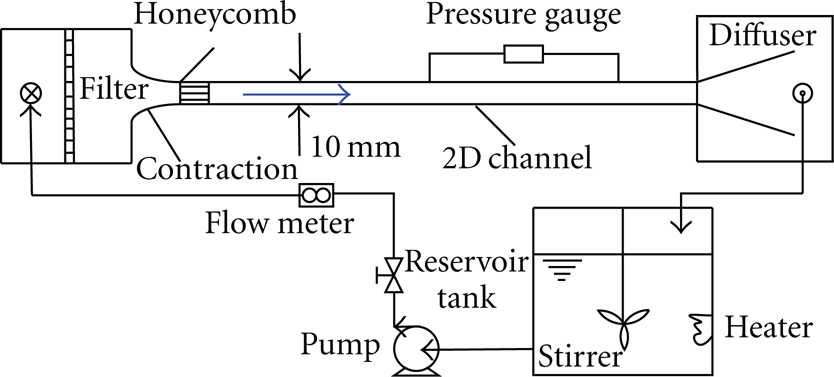
Schematic diagram of two-dimensional water channel.
The two-dimensional channel was 10 mm high, 125 mm wide, and 3 meters long (inside measurement), which was connected straightly by two sections of 1.5 meters each. Most of the test section was made of transparent acrylic resin having thickness of 20 mm. To remove large eddies, a honeycomb of 45 mm length was employed at the entrance of the test section. The flow rate and pressure drops were measured by an electromagnetic flowmeter with a resolution of ±0.01 m3/min and a precise pressure gauge with an uncertainty of ±0.1 Pa. The distance of two pressure tabs was 1.10 meters in length located 1.65 meters downstream from the entrance of the channel.
3. Pipe Diameter Effect and Scale-Up Method
3.1. Pipe Diameter Effect
For turbulent flow of Newtonian fluid through a smooth pipe, the friction resistance coefficient is only a function of Reynolds number and is expressed as

The above equation is the Karman-Prandtl resistance formula which is suited to fully developed turbulent flow through smooth circular tubes, where λ is friction resistance coefficient and Re is Reynolds number.
However, for drag-reducing fluids in the nonasymptotic region, this is not the case, even for the same drag reducer, the effects of friction reduction are different for different pipe diameters. This is the so-called “diameter effect” for drag-reducing fluids [6]. This effect indicates that the friction resistance coefficient is not only dependent on Reynolds number but also dependent on the pipe diameter. The friction resistance coefficient or Fanning friction factor C f can be expressed as

This effect is a vexing issue from the practical point of view. It is not very difficult to measure the drag-reduction level (DR) for a given fluid in tubes with diameters from 10 to 60 mm in the laboratory, but it is not easy for much larger pipes. In a hydronic system of a building, the pipe diameters vary from 40 mm to 350 mm, so it is better to predict DR in such a building system by using scale-up method [7].
3.2. Scale-Up Method
To solve the problem of “diameter effect” existing in the drag-reducing flows, some scale-up models and mathematical derivation methods have been developed in order to reduce or eliminate the “diameter effect” of the fluids. In 1968, Whitsitt et al. [8] proposed a method that correlates DR with the solution friction velocity (u p * ), based on the assumption that the wall being shear stress is the mechanism that controls DR, where the friction velocity is defined as u p * = (τ w /ρ)0.5, with τ w and u p * the wall shear stress and friction velocity, respectively, then plotted the drag-reduction level DR as a function of the solution friction velocity (u p * ). This is the so-called “correlate model of DR and u p * .” This procedure has the drawback that both variables (DR and u p * ) contain the unknown parameter (τ w ), and an iterative procedure is therefore necessary to predict the DR of the solution. A number of other researchers, for example, Astarita et al. [9], Lee et al. [10], and Savins and Seyer [11], then simplified Whitsitt's procedure by using the solvent friction velocity (u w * ) instead of the solution friction velocity (u p * ) and proposed “correlate model of DR and u w * .” After that, Schmitt et al. [12] proposed two different empirical correlations for surfactants depending upon the shear stress level: DR versus τ w for high stresses and τ w versus V (bulk velocity) for low stresses. Gasljevic and Matthys [13] proposed a new correlation model on the diameter effect of drag-reducing flow by correlating drag-reduction level (DR) with bulk velocity.
All the methods discussed above except for Schmitt's were developed for, and tested with, polymer solutions data. All these four models have very similar characteristics: there exists no theoretical or empirical formula; therefore, the specific analysis of these models can only be done after getting corresponding experimental data. Gasljevic et al. [6] proved that Schmitt's procedure was not universal; in other words, the fitting results have great distinctions for different surfactant solutions. Hoyt [14, 15] proposed a scale-up method for polymer additives pipes by introducing an additional term (ΔB) in the nondimensional pipe velocity profile. He simplified his scaling procedure by using the idea of negative roughness. ΔB is a function of the type of drag-reducing polymer, polymer concentration, pipe roughness, and so forth. The core equation and finally scale-up equation of this scaling procedure are as follows.
The core equation of this method is

The scale-up equation is

This scaling procedure appears to have an excellent accuracy based on a series of experimental data obtained by Hoyt. By using this scaling procedure, the predictions are almost consistent with each other and consistent with the experimental results. This behavior is illustrated in Figure 2, where the Fanning friction factor C f is plotted as a function of Reynolds number, Re.

Fanning friction factors versus Reynolds number. Solid triangles are the measured data of 119.4 cm diameter pipe. Solid squares are predictions of the 119.4 cm diameter pipe based on the 2.664 cm diameter pipe data, and solid circles are predictions of the 119.4 cm diameter pipe based on the 5.250 cm diameter pipe data. The solid line is the Dean line.
4. Test of the Scale-Up Method Proposed by Hoyt
Through the above discussion we can know that the scaling procedure proposed by Hoyt has great advantage compared with others. Therefore, in this study, we try to use this scale-up method to analyze and process the size effect of the CTAC/NaSal (Hexadecyl Trimethyl Ammonium Chloride/Sodium salicylate) surfactant flow. The ratio of CTAC to NaSal is 1 : 1 by weight. At the same temperature of 30°C and the same concentration of 100 ppm, the friction coefficient of CTAC surfactant solution shows great differences for different pipe diameters, which indicates that the CTAC surfactant solution has a strong size effect. The data for D1 = 18.5 mm (the equivalent diameter of 10×125 mm2 rectangular cross-section of a channel) obtained in the laboratory and the data for D2 = 74.1 mm (the equivalent diameter of 40×500 mm2 rectangular cross-section of a channel) got from the literature [16] are shown in Figure 3. The “Dean line” [17] for Newton fluid turbulent flow is also shown for comparison.

Measured friction factors for 100 ppm surfactant solutions in pipes of 18.5 mm and 74.1 mm diameters.
Figure 4 shows the prediction of friction factors of CTAC/NaSal surfactant flow in 74.1 mm diameter pipe from the measured data of D1 = 18.5 mm pipe at 100 ppm and 30°C, and the predicted values are compared with the actual test data for the larger pipe of D2 = 74.1 mm. At the beginning, the predicted values have some difference from the experimental values, but the difference becomes smaller and smaller with the increase of Reynolds number. The prediction agrees well with the measured data generally. Therefore, this scale-up method can be used in an actual districting heating system.

Comparison of measured friction factors of 74.1 mm diameter pipe with scale-up prediction based on the measured friction factors of 18.5 mm diameter pipe.
5. Prediction of Drag Reduction Performance of a District Heating System with Surfactant Additives
In consideration of the good applicability of the scale-up method proposed by Hoyt, we apply this method to predict the drag reduction performance of an actual district heating system with surfactant additives of CTAC/NaSal and thus evaluate the energy saving effect of the DHS by adding surfactant to the working fluid in the system.
The schematic of the district heating system in a community located in Qingdao City, Shandong Province, China, is shown in Figure 5, and the solid circles the connection points of different pipe diameters. The lengths, diameters, and flow parameters are shown in Table 1. Since the layouts of pipe networks in houses of users are not clear, we do not consider the branch pipes (shown as the thinner lines connecting buildings and comparative thicker lines in Figure 5) leading into specific houses. For example, the flowrate of pipe no. 15 is not equal to the flowrates in pipes no. 16, no. 17, and 18; it is because some of the fluid coming from pipe no.15 flows into building 1 which is not considered. The steam coming from the boiler enters the heat-exchanging station where the working fluid (water) gets heat from the steam to become hot water and then is supplied to the community users.
Parameters of the pipes in the DHS.


Schematic diagram of the DHS in a community.
The hot water pipes which are connected to the heat-exchanging station are divided into two branches: one branch is to the buildings in a comparative intensive residential area, and the other is to some worker dormitories. Temperatures of the supply and return water are 50°C and 41°C, respectively. The pipes used in this district heating system have several different diameters of 300 mm, 250 mm, 200 mm, 150 mm, 125 mm, 100 mm, and 80 mm. The diameter and length of the pipes and the corresponding flowrate are shown in Table 1.
Figure 6 shows the plot of the measured Fanning friction factors (C f ) as a function of Reynolds number (Re) for a 100 ppm CTAC/NaSal surfactant solution in the channel with the hydraulic diameter of 18.5 mm, and the corresponding predictions of friction factors by using (3) and (4) for seven different pipe diameters are also shown in Figure 6. The predicted curves shown in Figures 6(a) and 6(b) are based on the experimental data obtained in the 18.5 mm diameter channel at 50°C and 41°C, respectively.

Fanning friction factors of seven different diameters in the DHS predicted from the experimental data of the 18.5 mm diameter channel.
For both Newtonian fluid and non-Newtonian flow in the fully developed turbulent flow region, the wall shear stress (τ w ) and Fanning friction factor (C f ) are defined as follows:


where ΔP is pressure drop, D is equivalent diameter, L is distance between pressure taps, ρ is the fluid density, and u b is bulk velocity. In the engineering field, however, the commonly used parameter is friction resistance coefficient (λ) which is defined as
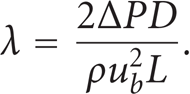
Comparing (7) with (6), we see that λ=4C f . We have two empirical formulas for the friction resistance coefficient, (1) and (2). Equation (1) is an implicit function of λ. In order to make λ a function of Re, Nikuladse proposed an empirical equation which is fitted in the region of 105┼Re┼3×10⁶ as follows [18]:

For Re┼105, we use the Blasius equation, thus

Before adding surfactant, we can calculate the pressure drop of pure water in a pipe by using the following equation:

The results show that the pressure drops of water in the supply and return pipes are 13209.12 Pa and 13667.51 Pa, respectively, and the total pressure drop is 26876.63 Pa.
After adding surfactant, the Fanning friction factor (C f ) for different pipe diameters can be obtained from Figure 6 and can be transformed to friction resistance coefficient (λ) according to (2). The pressure drop for the surfactant flow in the pipes can also be calculated by using (10). For the 100 ppm CTAC/NaSal surfactant solution, the pressure drops in the supply pipes and return pipes are 6758.30 Pa and 6842.10 Pa, respectively, and the total pressure drop is 13600.40 Pa. For the 200 ppm CTAC/NaSal surfactant solution, the pressure drops in the supply pipes and return pipes are 7498.54 Pa and 7164.89 Pa, respectively, and the total pressure drop is 14663.44 Pa.
All the above calculations are carried out only in straight pipes. In addition, there are two methods to calculate the local flow resistance of the district heating system: resistance coefficient method and equivalent length method [14]. We adopt the equivalent length method in the present study. The equation of this method is
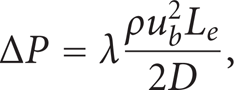
where L e is equivalent length of local fittings such as elbows, tee shape fittings, and valves. This method transfers local fittings to straight pipes which are L e long and have the same diameters with fittings, and then (11) is used to calculate the flow resistance. The equivalent lengths of different local fittings in the district heating system can be obtained in a relevant literature [14]. The calculated results of local fittings show that the pressure drops in the supply and return pipes are 5596.70 Pa and 24550.90 Pa, respectively, and the total pressure drop is 30147.60 Pa.
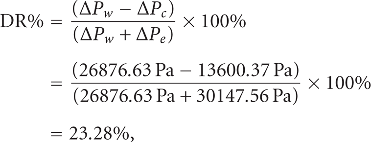
The analysis of the drag reduction of local fittings through the laboratory experimental study was given in detail in [19]. The results showed that the drag reduction effects of local fittings were not only affected by all factors affecting the drag reduction of straight pipe but also affected by two other factors: dimensionless local resistance coefficient and own structures of local fittings; what more, the increase in local resistance decreased the drag reduction effect until the drag reduction effect disappeared. Considering the average effects of all the local fittings on the drag reduction of surfactant solutions, Jiao [19] proposed that the drag-reducing behavior of CTAC/NaSal surfactant solution flow is observed just in the straight section of pipes rather than in local fittings. Therefore, we can calculate the rates of drag reduction for the 100 ppm and 200 ppm surfactant solutions as follows:
for 100 ppm
for 200 ppm

where ΔP w is the total pressure drop of straight pipes before adding surfactant, ΔP c is the total pressure drop of straight pipes after adding surfactant, and ΔP e is the total pressure drop of local fittings.
The drag reduction rates of both 100 ppm and 200 ppm are approximately 20%. Furthermore, the drag reduction effect of the 100 ppm CTAC/NaSal surfactant solution is a little larger than that of 200 ppm. The actual pressure drop in the district heating system in Figure 5 had been measured by Jiao et al. [5]. The results showed that with the same running frequency of the circulation pump, the water circulation flow rate in the tested system is increased by 11.7% and, with a constant flow rate, the pumping power (electricity consumption) could be reduced by 28.4%. These data are corresponding to a drag reduction of 24.7%, which agree well with our prediction.
In addition, the above analysis shows that the pressure drops of local fittings are considerable, but the drag reduction effects are extremely weak. Therefore, the designer should try to avoid using local fittings when designing the district heating system in order to improve drag reduction performance of the system by adding surfactant.
6. Conclusions
The drag reduction effects of CTAC/NaSal surfactant in a community district heating system was evaluated by using the scale-up method proposed by Hoyt, and the main conclusions are as follows.
The scale-up method of Hoyt is applicable to the CTAC/NaSal surfactant solution, and the data obtained in our setup confirms that the pressure drop in the system is reduced after adding surfactant in this system.
The drag reduction rates of the 100 ppm and 200 ppm CTAC/NaSal surfactants in the DHS are 23.28% and 21.42%, respectively, which are much lower than the drag reduction rates measured in the laboratory. This is due to the existence of local fittings in the DHS in which the flow resistance takes a very large proportion in the whole system but cannot be reduced by surfactant additives.
Footnotes
Acknowledgments
The authors gratefully acknowledge the financial support from the NSFC Fund (no. 51076124), the Specialized Research Fund for the Doctoral Program of Higher Education of China (no. 20090201110002), and Jiangsu Provincial Natural Science Foundation (BK2009145).