
Abstract
As more and more wireless devices use the 2.4 GHz radio spectrum, the coexistence of 2.4 GHz wireless devices operating in one place has become a hot topic. With low transmit power, the widely deployed IEEE 802.15.4-based networks are easily interfered with by other 2.4 GHz wireless networks, such as IEEE 802.11. IEEE 802.15.4-based wireless networks have paid great attention to the coexistence between themselves and with other non-IEEE 802.15.4 wireless networks. This problem has been further promoted by two new industry wireless standards, WirelessHART and ISA100, to meet special industry requirements. This paper surveys the studies on the coexistence between IEEE 802.11 and IEEE 802.15.4-based networks following the general analysis method of “question-analysis-solution.” Based on the survey study, we discuss about some open research issues and developments in this field.
1. Introduction
As MAC (media access control) and PHY (physical layer) specifications for low-rate wireless personal area networks, IEEE 802.15.4 [1] using 2.4 GHz ISM (Industrial, Scientific and Medical) band has obtained great success. ZigBee [2] based on IEEE 802.15.4 has been wildly researched and applied. Recently, as the demands of industry wireless application increase, two important industrial wireless network standards based on IEEE 802.15.4, WirelessHART [3], and ISA100 [4] have been approved. These wireless networks use the same 2.4 GHz ISM band; moreover, as a license-free radio band, 2.4 GHz ISM has also been widely used by many non-IEEE 802.15.4 wireless networks, so coexistence among them must be considered.
Considering the huge quantity of devices, high transmit power, and large coverage range, IEEE 802.11 [5] devices interfere with IEEE 802.15.4 most seriously. In this paper, we survey the studies on wireless coexistence between IEEE 802.11- and IEEE 802.15.4-based networks. Because of the dual characters of coexistence, IEEE 802.15.4 is not only a victim, but also an interferer sometimes. Compared with some similar work [6–8], this paper covers more recent studies and classifies the IEEE 802.15.4 coexistence research by different dimensions.
This paper follows the general analysis method of “question-analysis-solution” which divides the existing studies into three phases as shown in Figure 1. The first phase (Section 2) mainly discusses about the seriousness of coexistence problem. The second (Section 3) presents the analysis models of coexistence problem. The last (Sections 4 and 5) provides the solutions of coexistence problem.

General analysis method and organization of the paper.
Section 2 is mainly about the seriousness of coexistence between IEEE 802.15.4 and IEEE 802.11. Many studies based on experiment measure and computer simulation have revealed the seriousness of coexistence and given an intuitive understanding of IEEE 802.15.4 coexistence in quantity. Some coexistence parameters and coexistence scenarios are explored, which are novel and useful for future research.
Section 3 studies the analysis model of coexistence between IEEE 802.15.4 and IEEE 802.11. To organize the studies more logically, we use a behavioral input/output system, which includes three parts: input, behavior set and output. This system generates coexistence assessment parameters (output) which are determined by some initial coexistence environment parameters (input), and the current coexistence analysis models are behavior sets. To take a simple example, if sending power and network topology are input and wireless signal fading model is behavior set, the receiving or interference power is output. The input/output system presents a clear comparison study to understand different coexistence analysis models. We will see that even for the same input and output, there exist different behavior sets which are built for different research preferences and aims.
Sections 4 and 5 discuss about the solutions of coexistence between IEEE 802.15.4 and IEEE 802.11. The current solutions are summarized and divided into two types which we name inherent solutions and on-demand solutions, respectively. Section 4 introduces the inherent solutions that perform permanently and independently from interference. Section 5 introduces the on-demand solutions that perform dynamically according to the variety of interference. All of the on-demand solutions include two steps. The first step is to detect the level of interference. The second step is to take actions to avoid or reduce interference according to the detection results.
The paper summarises and reviews existing studies and, more importantly, illustrates future research development, open research issues, and possible solutions in Section 6.
2. Seriousness of Coexistence
All of the wireless system parameters that affect performance (such as modulation scheme, error correction, spread spectrum, frequency hopping rate, traffic character, packet size, offered load, transmission power, and network topology) can be divided into two types: (1) parameters that affect only the performance of the system where they are implemented; (2) parameters that affect the interactions between the interferer and the victim systems. Except for modulation scheme and error correction, almost all of the other parameters belong to the second type. This is why coexistence is a basic consideration for wireless network.
To study different coexistence parameters, there are many possible coexistence scenarios. In this section, we summarise some novel and useful studies in Table 1. The column “Environment” refers to the measure environment and parameters. The column “Conclusions” presents some important measure results and conclusions. In Table 1, we just list the parameters which are closely related with the conclusions.
Coexistence scenarios.

Before diving into the survey of measure studies, we list some interesting questions. (1) Which parameter is more responsible for coexistence interference? (2) Is the interference phenomenon the same for the sender and receiver? Between sender and receiver, which is easier to be interfered with? (3) Is it necessary to distinguish the coexistence interference between uplink and downlink?
“Bad case” means the interference is severe, and this scenario can explore parameters which are closely related to coexistence. Sikora and Groza in [9] and Pollin et al. in [10] both point out four parameters to form a bad case. Firstly, interferer and victim use overlapping channels; secondly, the network utilization rate is high for IEEE 802.11 or IEEE 802.15.4 or both; thirdly, there is short distance between the interferer and victim; finally, the interferer has a high transmit power. IEEE 802.15.4 is victim and interferer in [9, 10], respectively. The results show that the interference is serious in bad case. The results of [9] indicate that packet error rate is more than 90%. Experimental results in [10] show that the throughput loss of IEEE 802.11 can be up to 30%, and it can reach 60% for larger 802.15.4 duty cycles. The work in [9] also points out that the nonoverlapping channels may not provide a safe channel offset, because the signal strength is still rather high outside of IEEE 802.11 channel. We call it nonoverlapping interference.
Shuaib et al. in [11] advise the researchers to distinguish uplink and downlink when there is interference. There are two kinds of devices for IEEE 802.11: access point and terminal. We define the packets transmission from terminal to access point “uplink”, and the reverse “downlink” as shown in Figure 2. Experimental results in [11] show that if the IEEE 802.15.4 interferer is placed near the IEEE 802.11 source, interference has stronger influence on the IEEE 802.11 uplink (Figure 2(b)) than on the downlink (Figure 2(a)). The reason could be the different transmission power between access point and terminal. The transmission power of terminal is lower than that of access point, causing a stronger interference with access point than terminal. This phenomenon is easy to understand, but it advises us to remember the complexity of wireless coexistence. Because IEEE 802.15.4-based network also distinguishs uplink and downlink, the above results can also apply to the interference with IEEE 802.15.4 by IEEE 802.11.
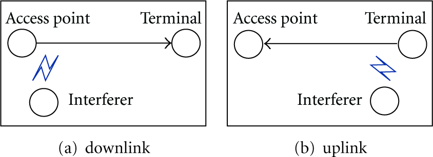
Interference on downlink and uplink.
Angrisani et al. in [12] reveal an interference phenomenon depending on the case of the IEEE 802.11 access point transmitting to the terminal or vice versa. In particular, in the case of the access point transmitting to the terminal as shown in Figure 3(a), when the IEEE 802.11 source is located far away from the IEEE 802.15.4 interferer, interference comes out as collisions between IEEE 802.15.4 and IEEE 802.11 data packets and/or channel errors. Conversely, in the case of the terminal transmitting to the access point as shown in Figure 3(b), when the IEEE 802.11 source is located closely to the IEEE 802.15.4 interferer, interference comes out as channel occupation due to the presence of IEEE 802.15.4 emissions in the IEEE 802.11 channel and the use of the CSMA/CA mechanism in the IEEE 802.11 transmitter. Actually, the above results can also apply to the interference with IEEE 802.15.4 by IEEE 802.11.

Interference on receiver and sender.
Angrisani et al. in [12] also show some important measure methods and results when IEEE 802.15.4 interferes with IEEE 802.11. One of the most important measurements aims to illustrate the relationship between the PLR (packet loss ratio) and SIR of IEEE 802.11 when IEEE 802.15.4 interference occurs. The measurements show that PLR is mostly determined by SIR, and there are three important SIR threshold values for PLR. The first is the minimum value that enables IEEE 802.11 to work, and the SIR should always be greater than this minimum value. The second is the threshold value, meaning that a greater SIR will not significantly decrease PLR. In other words, once this SIR is obtained, a further optimization to decrease interference from IEEE 802.15.4 is a waste. The third is an inflexion which means that PLR will abruptly worsen for SIR values that are below the inflexion. In the measure environment settings of [12], these three threshold values are −13 dB, −7 dB, and −11 dB, respectively.
Unlike other studies on IEEE 802.11b/g, Petrova et al. in [13] measured the interference with IEEE 802.15.4 by IEEE 802.11n and compared the measure results with IEEE 802.11g. The main difference between IEEE 802.11n and IEEE 802.11b/g lies in the network throughput improvement. IEEE 802.11n uses several technologies to improve throughput, including using wider channel bandwidth. Compared with IEEE 802.11b/g which uses 22 MHz channel, IEEE 802.11n supports 40 MHz channel, so the measurement shows that one IEEE 802.11n working channel interferes with IEEE 802.15.4 more seriously than IEEE 802.11g. Sikora and Groza in [9] identify the existence nonoverlapping interference, and Petrova et al. in [13] further explore that this type of interference can affect the sender. The measurement in [13] shows that packet loss at IEEE 802.15.4 receiver in nonoverlapping channels is caused by the sender's unsuccessful delivery of the packets rather than by the channel error.
Another significant measurement in [13] is the effect of different orientations of IEEE 802.11n transmission on IEEE 802.15.4 devices. As shown in Figure 4, the IEEE 802.11 terminal is the only device changing the position. When IEEE 802.11n traffic is at 90°, IEEE 802.15.4 has the best performance. The second best performance of IEEE 802.15.4 can be observed when IEEE 802.11n traffic is at 180°. When the IEEE 802.11n nodes are in line with IEEE 802.15.4 nodes, namely at 0°, both the overlapping IEEE 802.15.4 channels and the neighboring channels are heavily affected by the IEEE 802.11n.

Interference from different orientations.
3. Analysis of Coexistence
We use an input/output system to study the current mathematical analysis of coexistence between IEEE 802.11 and IEEE 802.15.4 as shown in Figure 5. This system aims to generate interference assessment parameters (output) that are usually determined by other initial coexistence parameters (input). Mathematical models (current research models) are defined by behavior sets. For a system with input u and v, output w and x, behavior set z and y, it is represented by the following formula:


Input/Output system.
Table 2 summaries input, output, and behavior set of the current studies. It should be noted that outputs from one system can be inputs of another system. The PFM (path fading model) is the basic behavior set in Figure 5, whose output is SINR (signal interference and noise ratio). Almost all of the other behavior sets use SINR as input directly or indirectly. For example, based on SINR, we can analyze BER (bit error rate) using ICM (interference channel model); based on BER, we can further analyze PER (packet error rate) using IPM (interference protocol model). The difference among these ICMs and IPMs is the accuracy to analyze coexistence problem.
Input/Output and Behavior sets.

Some interesting questions in this section are as follows: (1) what are the differences among the three CCA (clear channel assessment) models? (2) which layer (physical layer, MAC layer or higher layer) do the models of coexistence belong to? What are the differences among those models?
3.1. IEEE 802.15.4 as Victim
3.1.1.
Path fading model (PFM) is the basic behavior set for most current studies on IEEE 802.15.4 wireless coexistence. To assess the level of interference, usually the victim needs to know the levels of power from sender and interferer and then calculate the SIR which can be used as a simple expression (physical layer expression) of interference.
Considering that IEEE 802.15.4 devices are used for short range communication, the PF model in [14] uses the indoor propagation model [15, 16], and then, the path loss between transmitter and receiver can be expressed by 
The bandwidth of the IEEE 802.11b is 22 MHz, much larger than that of the IEEE 802.15.4, 2 MHz. So the signal from the IEEE 802.11b, the interferer, can be modeled as the signal from band-limited AWGN to the IEEE 802.15.4 [17]. Then, the SINR can be determined by
3.1.2.
With the SINR, bit error rate (BER) can be calculated, which is more useful than SINR in interference assessment, but it is still a physical layer expression. We call this calculation model interference channel model (ICM). Shin et al. in [14] and Han et al. in [18] give two different ICMs.
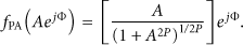
In [14], the PHY of the IEEE 802.15.4 at 2.4 GHz uses offset quadrature phase shift keying (O-QPSK) modulation with half-sine pulse shaping, which is equivalent to MSK (minimum shift keying) [19]. Let 
3.1.3.
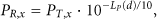
Carrier frequency offset between interferer (IEEE 802.11) and victim (IEEE 802.15.4) is also important to analyze the interference. Because the bandwidth of the IEEE 802.11b is 11 times that of the IEEE 802.15.4, in-band interference power of the IEEE 802.11b interferer to the IEEE 802.15.4 user is usually calculated as
Most current researches assume that IEEE 802.15.4 under the interference of the IEEE 802.11b with 0 frequency offset and the in-band interference power is calculated as
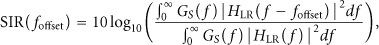
Howitt and Shukla in [20] studies the relationship between the SIR in conjunction with the frequency offset between the interference and desired signal in order to evaluate how these may disrupt packet transmission and introduces an analytical model for interference suppression versus carrier frequency offset. The relationship between SIR and frequency offset is

3.1.4.
An intuitive expression of interference is packet error rate (PER), which can be calculated from BER. We call the calculation model interference protocol model (IPM). In current studies, the packet of PER is always MAC layer frame. So the interference protocol model means MAC layer protocol.
Shin et al. in [14] give a simple interference protocol model (IPM1) with the following assumptions. First, there is only one IEEE 802.11 interferer. Second, the carrier detection method of IEEE 802.15.4 is CCA model 2, which means that IEEE 802.15.4 users are transparent to IEEE 801.11 users, and vice versa. In other words, they transmit the packets without considering whether the channel state is busy, resulting in the worst case. Finally, acknowledgment (ACK) packets of both IEEE 802.11 and IEEE 802.15.4 are not considered in IPM1.
3.1.5.
Shin et al. in [23, 24] improve the interference protocol model based on IPM1. Although IPM2 still uses CCA model 2, it supports multiple IEEE 802.11 interferers (with saturated traffic), and ACK is considered.
3.1.6.
For IEEE 802.15.4 and IEEE 802.11, the PHY shall provide the capability to perform CCA according to at least one of the following three modes.
CCA Mode 1 (energy above threshold)
CCA shall report a busy medium upon detecting any energy above the ED (energy detection) threshold.
CCA Mode 2 (carrier sense only)
CCA shall report a busy medium only upon the detection of a signal compliant with this standard with the same modulation and spreading characteristics of the PHY that is currently in use by the device. This signal may be above or below the ED threshold.
CCA Mode 3 (carrier sense with energy above threshold)
CCA shall report a busy medium using a logical combination of Model 1 and Model 2.
Using the CCA model 1 and 3 improves coexistence by allowing transmission backoff if the channel is occupied by any device, regardless of the communication protocol it may use. The choice of the optimal CCA threshold value is very important to mitigate coexistence interference.
Considering the importance of CCA model, Yuan et al. in [25] try to build a more reliable IPM (IPM3). IPM3 introduces the concept of coexistence range to classify the CCA models. The interactive behavior of IEEE 802.15.4 nodes and IEEE 802.11 nodes is different (different CCA models are used) in different ranges.
The transmission powers of IEEE 802.11b/g nodes and IEEE 802.15.4 nodes are significantly different. The differences of the transmit power and the receiver sensitivity lead to three distinct ranges R1, R2, and R3 as defined below.
R1
A range in which IEEE 802.15.4 nodes and IEEE 802.11 nodes can sense each other, and therefore both of their CSMA/CA mechanisms work, that is, as one is transmitting, the other has to wait. In this case, CCA model 3 (including CCA model 1 and 2) works for both IEEE 802.15.4 and IEEE 802.11 nodes.
R2
A range in which IEEE 802.15.4 nodes can sense IEEE 802.11b/g nodes but not vice versa, because the transmit power of IEEE 802.11b/g nodes is much higher than that of IEEE 802.15.4 nodes. Thus, when IEEE 802.11b/g nodes are transmitting, IEEE 802.15.4 nodes are waiting, but when IEEE 802.15.4 nodes are transmitting, IEEE 802.11b/g nodes cannot detect them and simply proceed to transmit, probably causing an overlap in packet transmissions. In this case, CCA model 3 (including CCA model 1 and 2) works for IEEE 802.15.4, and CCA model 2 works for IEEE 802.11 nodes.
R3
A range in which neither IEEE 802.15.4 nodes nor IEEE 802.11b/g nodes can sense each other. However, IEEE 802.15.4 nodes may still suffer from the IEEE 802.11b/g interference, because a range in which a wireless device can cause interference with others is usually larger than that where it can be sensed by the others. This means both of IEEE 802.15.4 nodes and IEEE 802.11b/g nodes can freely transmit packets without deferring the other, which is described as blind transmissions in [14]. In this case, CCA model 2 works for both IEEE 802.15.4 and IEEE 802.11 nodes.
3.1.7.
Different from other studies, IPM4 in [26] just considers the MAC layer. Without considering physical layer protocol and parameters (such as TP and NT), IPM4 assumes that IEEE 801.11 and IEEE 802.15.4 devices interfere with each other if they transmit simultaneously. So the interference is determined only by MAC layer protocol and network loading (NL). Carrier detection model is CCA model 1 in IPM4, because all of the IEEE 801.11 and IEEE 802.15.4 devices interfere with each other. IPM4 is built by a Markov chain analysis model. Combining IPM4 with other ICMs may produce more analysis models applicable for study on IEEE 801.11 and IEEE 802.15.4 coexistence.
3.1.8.
More performance parameters affected by interference are analyzed in [27], such as transmission delay (TD) and throughput (TH) of MAC layer frame. Delay model (DM1) is introduced in [27] to calculate these parameters. Transmission delay is defined as the total time from the moment a source station accesses a channel to the moment when a destination station receives an ACK packet. The throughput is the amount of data transferred from one station to another station during a specified period of time. The throughput is calculated from the PER and the average transmission delay.
3.2. IEEE 802.15.4 as Interferer
3.2.1.
As PFM is independent of physical layer and MAC layer protocol, it remains unchanged no matter IEEE 802.15.4 device is victim or interferer. Yoon et al. in [28] use the same PFM as (2) and (3) to calculate RP and SIR.
3.2.2.
Yoon et al. in [28] introduce ICM2 to calculate BER of IEEE 802.11b that is interfered with by IEEE 802.15.4.
The IEEE 802.11b PHY provides dynamic data rate, which is obtained through the combination of different modulations and codes. It is possible for the data rate to shift up to 11 Mbps using CCK (complementary code keying). 
3.2.3.
Symbol error rate (SER) is another indirect expression of interference, and it can be used to calculate PER further. Roy and Jamadagni in [30] introduce an analytical model ICM3 to get IEEE 802.11 SER in the presence of ZigBee interference in AWGN and Rayleigh fading channel.
3.2.4.
IPM5 in [28] is as simple as IPM1. For IPM5, there is only one IEEE 802.15.4 interferer. The carrier detection method of IEEE 802.11 is CCA model 2. ACK packets are considered in IPM5.
3.2.5.
IPM6 in [31] is the extension of IPM5. IPM5 assumes that all packets of 802.11b are broadcasting packets and does not consider the backoff time and the transmission of ACK packets, while IPM6 takes both factors into account.
3.2.6.
IPM7 in [32] improves IPM5 to support multiple IEEE 802.15.4 interferers.
3.2.7.
DM2 in [27] is used to calculate transmission delay (TD) and throughput (TH) of IEEE 802.11 MAC layer frame under the interference of IEEE 802.15.4.
4. Inherent Solutions of Coexistence
Inherent solutions are performed permanently to mitigate the interference. Most of inherent solutions have been included into IEEE 802.15.4-based network standards and perform independently of interference.
Table 3 lists current inherent solutions of different IEEE 802.15.4-based network standards. The second column is a simple description of the solutions. The third column is the basic principle of interference mitigation. The essence of coexistence problem is the conflict of spectrum resource, so the basic principle for interference mitigation is to avoid collision by three kinds of resource sharing (frequency, time, and space).
Inherent solutions.

Some interesting questions in Sections 4 and 5 are as follows: (1) which layer (physical layer, MAC layer, or higher layer) does the solution come from? What are the differences among the solutions in different layers? (2) what is the difference between the following on-demand solutions: central control and distributed control, single node action and cooperation action, passive action and cognitive action, and individual (MAC dependent) and universal (MAC independent)?
4.1. Solutions in IEEE 802.15.4
IEEE 802 standards family, which includes IEEE 802.15.4, IEEE 802.15.1, and IEEE 802.11, has paid great attention to wireless coexistence. For a standard in the IEEE 802 family to be approved, a “Coexistence Assurance” document must be provided and approved. The coexistence approval process usually involves IEEE members working together to ensure that all 802 wireless standards can coexist in the same space at the same time (further details on the coexistence of IEEE 802.15.4 with other IEEE standards can be found in Annex E of the IEEE 802.15.4-2003 standard [1]). In addition to these assurance documents, there are two special task groups of coexistence. The IEEE 802.15 coexistence task group two (IEEE 802.15.2) for wireless personal area networks developed recommended practices to facilitate coexistence of wireless personal area networks (802.15) and wireless local area networks (802.11). The IEEE 802.19 Coexistence technical advisory group develops and maintains policies that define the responsibilities of 802 standards developers in addressing issues of coexistence with existing standards and other standards under development.
The basic idea of spread spectrum is to transmit the signal over additional bandwidth, using more frequencies but less power per frequency. One of most used spread spectrum is direct sequence spread spectrum (DSSS), which is used to promote coexistence of IEEE 802.15.4. DSSS makes use of a pseudorandom code sequence, often called a “chipping sequence,” which is transmitted at a maximum rate called the chip rate. The chipping sequence is used to directly modulate the basic carrier signal and to encode the data being transmitted.
In addition to DSSS, IEEE 802.15.4 increases the opportunities for coexistence by employing a technique, generally known as frequency division multiple access (FDMA), which divides the 2.4 GHz ISM band into 16 nonoverlapping channels, which are 5 MHz apart. At least two of these channels, specifically 15 and 20, fall between the often used and nonoverlapping 802.11 channels 1, 6, and 11 as Figure 6.
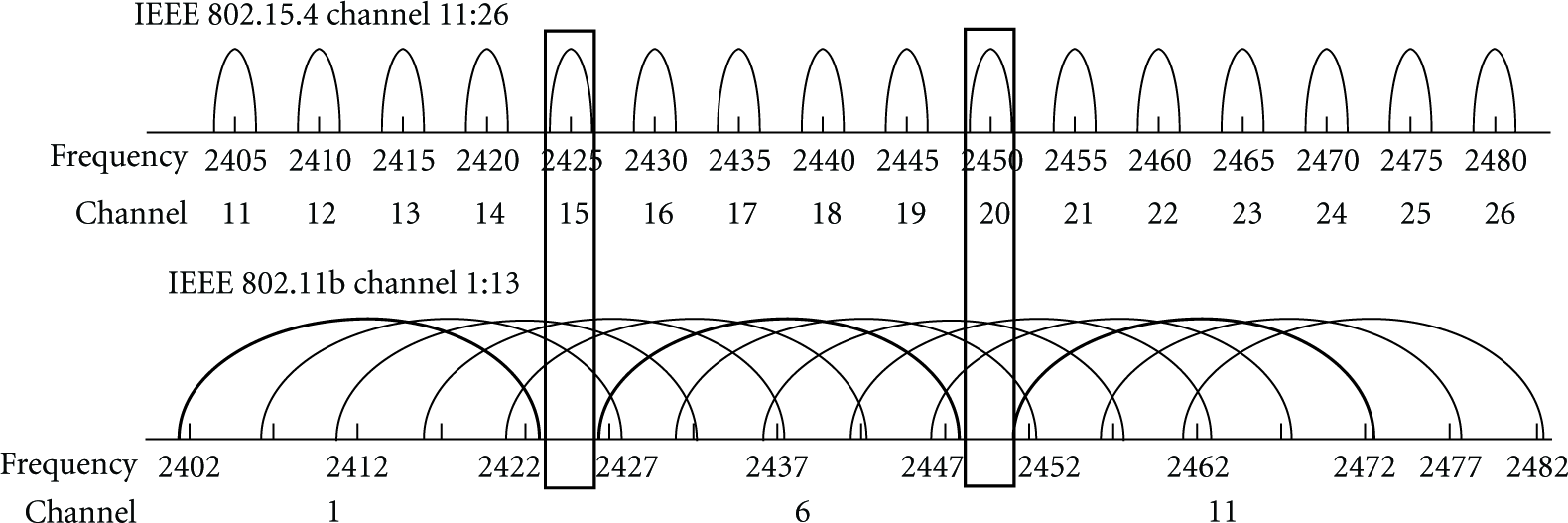
Channel assignment in 2.4 GHz band.
Even with the techniques described above in place, an IEEE 802.15.4 device may find itself sharing a channel with interferers. There are a number of ways to solve this problem, and the approach taken by the IEEE in the 802.15.4 standard is known as carrier sense multiple access with collision avoidance (CSMA/CA). A similar technique, carrier sense multiple access with collision detect (CSMA/CD), which has been used successfully for years in Ethernet, has the virtue that it requires no synchronization between devices. Instead, it employs a simple “listen before you talk” strategy.
In addition to CSMA, IEEE 802.15.4 also supports time division multiple access (TDMA) to control access to the network. TDMA is a widely used MAC technique that provides collision-free, deterministic communications. TDMA uses time slots where communications between devices occur. A series of time slots form a TDMA superframe. Superframes are repeated continuously. Typically, two devices are assigned to a given slot. One is designed as the source, and the other is the destination.
Most of the intended applications for IEEE 802.15.4 devices require a very low data rate; however, IEEE 802.15.4 chooses a relatively high data rate, 250 Kbps, because a radio with high data rate occupies the channel far less and leaves lower chances for collision.
Using a shorter packet length can generally reduce the packet loss. The IEEE 802.15.4 specifies the maximum number of bytes that can be transmitted in the MAC data payload as 102 bytes.
4.2. Solutions in ZigBee
The ZigBee protocol standard [2], which is built on top of IEEE 802.15.4, provides additional benefits of a well-developed wireless networking standard that is designed, built, and supported by hundreds of the world's leading technology companies. Most of these companies have thoroughly and independently investigated the coexistence capability of ZigBee and IEEE 802.15.4. ZigBee Alliance in [33] introduces coexistence techniques. There are also numerous technical reports of coexistence from ZigBee member companies [34–37].
When a ZigBee network is created, the ZigBee coordinator is required to scan the list of available channels and automatically select the channel with least interference.
Mesh network can provide path sharing and dynamic routing to improve coexistence.
ZigBee devices use the scanning facilities in IEEE 802.15.4 to detect interference and report the detection result to the ZigBee coordinator. The coordinator may direct the network to leave the channel it is currently using and turn to another one.
4.3. Solutions in WirelessHART
WirelessHART is the first open wireless communication standard specifically designed for process measurement and control applications. Like ZigBee, physical layer and parts of MAC layer in WirelessHART are based on IEEE 802.15.4, considering that industry circumstances have high demands on robustness, coexistence, power consumption, security, and so on, WirelessHART is like an enhanced version of ZigBee. Many new technologies are introduced into WirelessHART, such as frequency sharing, path sharing, and blacklist [38]. Most of these new technologies relate to improving the coexistence capability.
WirelessHART introduces channel hopping and combines it with TDMA. Channel hopping provides frequency sharing, which can avoid interference and reduce multipath fading effects. TDMA enables efficient low-power and reliable channel hopping communication because the synchronization of the slot and channel used by the communicating devices allows them to rendezvous in time and frequency, thus promoting successful communications.
Channel blacklisting of WirelessHART allows the network administrator to restrict the channel hopping to selected channels. For example, network administrators can blacklist channels in order to protect a wireless service that uses a fixed portion of 2.4 GHz band that would otherwise be shared by other WirelessHART devices.
4.4. Solutions in ISA100
ISA100 is another industry wireless network standard based on IEEE 802.15.4. To meet the needs of industrial wireless users and operators, ISA100 provides robustness in the presence of interference in harsh industrial environments and with legacy non-ISA100 compliant wireless systems. The Clause 4 [39] of ISA100 addresses coexistence with other wireless devices in the industrial workspace, such as cell phones and devices based on IEEE 802.11x, IEEE 802.15x, IEEE 802.16x, and other relevant standards.
Multihop network repeats the same message multiple times, which is easier to be interfered with. One fundamental capability of ISA100 architecture is to transfer the data packets as directly as possible.
ISA100 tries to minimize network overhead for most applications, which provides lower duty and shorter packet and therefore avoids interference.
ISA100 distinguishes different applications based on latency requirement. Many of the focused applications in ISA100 have less stringent latency requirements than other users of the spectrum, providing an opportunity to use time sharing for coexistence. Configurable retry periods potentially spanning hundreds of milliseconds enable the system to coexist with other users of the spectrum that may need to use the band for high-priority bursts of activity.
The probability of an external device mistaking a packet for its own is reduced since retransmissions have different physical layer payloads due to the data link layer inherent security. This mechanism minimizes the mistaken retransmissions in ISA100 network.
Adaptive channel hopping is the technique whereby a device may autonomously treat transmit links on problematic channels as idle, thus reducing unnecessary interference and energy consumption on channels with a history of poor connectivity. Adaptive channel hopping can be disabled by the system manager on a link-by-link basis.
4.5. Solutions in IEC TC65/ SC65C/WG17
The international electrotechnical commission (IEC) [40] is a worldwide organization for standardization comprising all national electrotechnical committees (IEC National Committees). The object of IEC is to promote international cooperation on all questions concerning standardization in the electrical and electronic fields. A work group of IEC, TC65/ SC65C/WG17, is “wireless coexistence.” The task of this work group is to provide definitions and guidance for coexistence of different wireless devices and networks taking into account the regional and national regulations. Because WG17 belongs to SC65C (industrial networks), it cares about industrial wireless network based on IEEE 802.15.4.
IEC standard [41] illustrates that most often the coexistence of several radio systems is feasible, if an appropriate approach is chosen, taking into account the respective requirements. In order to achieve this, a process is needed in which all aspects of the coexistence of radio systems during design, commissioning, and operation as well as maintenance are considered. This process called coexistence management system, which is used to select a radio solution dynamically. Coexistence management system considers all of the three sharing resources: frequency, time, and space. Figure 7 outlines the process of coexistence management and presents the relationships between the selection of a radio solution, the implementation of a coexistence management, and the actual coexistence management process.

Selection of a radio system and coexistence management.
5. On-Demand Solutions of Coexistence
On-demand solutions are performed dynamically according to the variety of interference. Most of on-demand solutions include two steps. The first step is to determine the level of interference. The second step is to take actions according to the level of interference.
5.1. Decision of the Level of Interference
We classify the detection criteria into two types as shown in Table 4. The first type is physical layer criterion, which is usually obtained from physical layer parameters (directly from the chip register) or more refined criteria based on other physical layer parameters. The second type is MAC layer criterion, which considers the receiving behavior of MAC frame. The evident difference between the two types reflects the tradeoff between accuracy and cost.
Measure criteria.

5.1.1. Physical Layer
We conclude five physical layer criteria: received signal strength indicator (RSSI), energy detection (ED), link quality indication (LQI), and noise floor (SSI noise). In addition to these parameters, two more refined criteria are interference temperature (IT) and capacity rate. Of course, refined criteria require more cost.
RSSI and ED are estimated values of the received signal power over some time. Several studies [42–45] use RSSI and ED to detect the level of interference. Measurement results in [42] show the considerable correlation between high RSSI and increased packet loss due to interference.
In addition to RSSI, CC2420 provides an additional hardware indicator, LQI, which is a measure of chip error rate. Hauer et al. in [46] use RSSI and LQI to measure the degree of interference from IEEE 802.11 devices. Measurement results show that RSSI seems barely affected by the 802.11 traffic, but LQI shows higher variance. This is understandable since LQI represents a measure of correlation between 802.15.4 chips; single chips may be corrupted by interference from IEEE 802.11 devices, while the symbols are still correctly decoded. While LQI can make more precise estimates, doing so requires averaging over many readings, which decreases agility and increases the estimate cost.
Hauer et al. in [46] also use SSInoise to detect the interference. SSI noise is the original value of RSSI in CC2420. Measurement results show that a single SSI noise value is rather unreliable in determining the presence of an interferer. A possible explanation is that the IEEE 802.11 devices are not permanently transmitting, but SSI noise is an instantaneous value rather than an average value over some time.
IT is considered a critical interference metric for intensive and dynamic use of the spectrum. Haron et al. in [47] interpret IT model and investigates how IT can be measured in coexisting networks of WLAN and WSN.
Capacity rate is another refined detection criterion introduced in [45], which is obtained from the knowledge of the probability distribution function (Pdf) of the interfering signal. Capacity rate allows a refined channel evaluation and makes the normalized capacity rate a suitable metric for the channel selection in adaptive WSNs or cognitive radio networks.
5.1.2. MAC Layer
Interference detection in physical layer is easy to implement, but it is not the optimum selection. Our ultimate purpose is to send or receive an MAC frame correctly, rather than detect physical interference. Interference detection in layers above MAC layer is not a good choice, either. Because of retransmissions in MAC layer, no packets are lost at the IP layer and the devices cannot find interference. Of course, if adding the consideration of delay, IP layer can find interference, but it is too complicated. So interference detection in MAC layer is a good choice.
There are many ways to describe the receiving MAC frame behavior in IEEE 802.15.4 coexistence studies, and the most common one is packet loss [14, 48], and others are packet delivery [13], packet error [49], Packet Collision [20], and so forth. All of the criteria have the same essence which is to describe the receiving of MAC frame under interference. The difference among them is the mechanism to obtain them, such as using test frame or retransmission counting.
A simple detection mechanism is based on counting beacon frame at the beginning of each superframe [48]. These methods are simple and do not require redundant procedures to detect interference; however, they could not satisfy all kinds of needs. Because interference detection mechanism based on ACK/NACK is a passive detection, only sending devices can detect interference with this method. However, in most cases, not only the sending devices but also some other related devices need to detect interference. For example, in a cluster-tree IEEE 802.15.4 network, the devices in a group use the same channel. If the sending devices detect interference and change to a safe channel, other devices in the group must also know the interference and change channel. Nonsending devices can acquire the interference event by either passive detection or active detection. For passive detection, the sending devices send a broadcast message to notify the nonsending devices [43, 48]. However, it is highly possible that the devices in the interference range cannot hear these broadcast messages because of strong interference. Then active interference detection is necessary. Kang et al. in [48] introduce an active interference detection scheme, using test frame to detect interference for some important communication links.
5.2. Actions to Handle the Interference
After detecting a high level of interference, wireless devices must take action to mitigate the interference. We name these actions on-demand solutions to differentiate the “inherent solutions.” Although the performing time is different for inherent and on-demand solutions, the principle of mitigating the interference is the same, which is to share the conflicting resources such as frequency, space, and time. We categorize the on-demand solutions in Table 5.
On-demand solutions.

5.2.1. Frequency Sharing Solution
Frequency sharing solution means that victim or interferer changes to a clean channel when they detect interference. Frequency sharing solution can be divided into two types, central control, and distributed control. Central control relies on a real or virtual center to coordinate channel change (which requires a dedicated interference-free channel). Yun et al. in [50] use PAN coordinator as center, while Musaloiu and Terzis in [42] use gateway. Won et al. in [43] and Kang et al. in [48] use broadcast message to coordinate with each other. An important difference among central control solutions is the scope of channel change in the presence of interference. Distributed control does not rely on any coordination, but every device should run the same algorithm to guarantee that communicating devices change to the same channel. This increases the complexity.
Yun et al. in [50] give a simplest solution based on central control frequency sharing. PAN coordinator is used as central control, which has to manage candidate channel set by periodically checking other channels during inactive period and notifying to other devices. The scope of channel change in [50] is the whole network, which means when one device detects interference, all the other devices in the IEEE 802.15.4 network have to change to the same frequency. This is not necessary for a multihop or cluster IEEE 802.15.4 network, and it could not deal with the case when different parts of the IEEE 802.15.4 network have different interferences (i.e., interferences with different frequency).
Musaloiu and Terzis in [42] tried to minimize the effect of IEEE 802.11 interference in IEEE 802.15.4 multihop wireless sensor networks, and the scope of channel change is based on a path. The solution includes two phases: during the first phase, each of the nodes on the multihop path between the sensing node and the gateway independently senses the RF spectrum to select the radio channel with least noisy. In the second phase, the nodes collaborate to agree on the common channel that is least congested across the whole path (which is coordinated by center gateway). Once this voting phase terminates, all nodes switch to the agreed upon channel, and the actual data transfer occurs. The selected channel will be used throughout the entire download operation. Unfortunately, some uninterfered nodes have to frequently change channel.
Unlike the study in [42], Won et al. in [43] limit the scope of channel change as an interference group, in which all of the devices are interfered, considering a multihop IEEE 802.15.4 network in which a part of the network (interference group) is interfered by IEEE 802.11b. Since the nodes are connected in multihop mesh network, packets are routed by visiting the nodes on the routing path. Packets cannot go through the interference group. The basic idea of the adaptive scheme is to make the interference group devices switch to a new clean channel. When packet is entering or leaving the interference group of the routing path, the radio channel is switched to a new clean channel or back to the old channel. The advantage of the proposed scheme is that the same routing path can be used when interference occurs. The interference group is surrounded by border nodes. The border nodes consist of immediate neighbors of the group and provide channel conversion for the group. To form the interference group and its border nodes, the node participating in interference group starts broadcasting GF (group formation) message to its immediate neighbors telling that it will change its current radio channel to a new one. Depending on the strength of the interference, nodes may or may not receive GF message. On the receipt of GF message, the node needs to decide to become a border node. The decision is made depending on the clearness of its channel. Only if the current channel is clear, the node will become the border. The forming of interference group and its border nodes relies on an assumption that communication between nodes on a channel is possible, even after interference has been detected on that channel. The problem is that it is highly likely that devices in the range of interferers cannot listen to the GF message because of strong interference. Kang et al. in [48] propose an adaptive interference avoidance algorithm for IEEE 802.15.4 cluster-tree networks. Cluster is the scope of channel change. Because all of the devices in a cluster should change to a same channel when there is interference, the algorithm in [48] faces the same problem as the algorithm in [43]. To avoid this problem, Kang et al. in [48] introduce more interference detection schemes (ACK/NACK based, the beacon based, and the test frame based) and channel change broadcast message (CCBM) to guarantee interference detection.
Central control solutions rely on the availability of a dedicated control channel, which drastically restricts the scalability and robustness of IEEE 802.15.4 network. Moreover, they do not consider the consumption of system power for environment scanning. Pollin et al. in [51] design a distributed channel selection algorithms that allow the sensor nodes to dynamically adapt to their channel in response to the IEEE 802.11 interference. The energy cost of the proposed algorithms will always be considered. Solution in [51] lets the devices select the channel by themselves when interference occurs. The quality of the channel is decided by hearing beacons. It is assumed that no beacon can be heard in the presence of IEEE 802.11 interference. Every period, next to the node i's current frequency channel
Zhou et al. in [52, 53] improve the work of [51] in two aspects. Firstly, they propose SAS, a self-adaptive spectrum management middleware independent of MAC protocol. SAS enables single-frequency MAC protocols to have multifrequency capability, so that an existing MAC protocol, like B-MAC, can automatically adapt to the least congested physical channel at runtime. Secondly, several new methods including toggle snooping, modified CCA, and receiver ID are introduced to make sure that communicating devices (sender and receiver) switch to the same channel. Toggle snooping implements snooping on three frequencies:
5.2.2. Time Sharing Solution
Unlike frequency sharing solutions, most time sharing solutions need cooperation between victim and interferer, which means that the solution must work on victim and interferer simultaneously. Time sharing solution can be implemented by time interval control [54–56], which means that different time intervals are used by different network devices (like a TDMA). Time sharing can also be implemented by traffic control [47]. A lager packets interval can reduce the probability of packet conflict at time dimension.
Jung et al. in [54] propose a proactive and node-centric scheme to mediate the intersystem interference of WLAN and ZigBee devices. The proposed algorithm finds the ZigBee channel that is least interfered with and prevents the WLAN from interfering with the selected ZigBee channel during a specified duration, called the WLAN interference-free time interval, for ZigBee data transmission. Jung et al. in [55] improve the work in [54] and introduces a network-centric interference mediation scheme in an overlaid network environment of WLAN and ZigBee devices.
Zhou et al. in [56] propose BodyQoS, the first running QoS system demonstrated on an emulated body sensor network. When the effective bandwidth of the channel degrades due to radio interference or body fading effect, BodyQoS adaptively schedules the remaining bandwidth to meet the QoS requirements. The QoS scheduling is based on a virtual MAC which is independent of any specific radio platform. This virtual MAC mainly implements time interval control. Time in VMAC is broken into intervals. Within each interval, VMAC is able to send out a certain number of packets with the specified data payload length, each within a specified time period.
Haron et al. in [47] present interference temperature to characterize both interference and noise in wireless sensor networks (WSNs) application. By measuring the interference temperature before data transmission, cognitive node is able to determine data rate that could be used to achieve desired capacity.
5.2.3. Space Sharing Solution
For an installed IEEE 802.15.4 or IEEE 802.11 network, it is impractical to move the devices frequently. On the other hand, there is close relationship between power fading and distance. Therefore, space sharing is often implemented by transmit power control [46, 47, 57, 58] or receiving power sensitive (CCA threshold control) [13, 59, 60].
Maximum transmit power level and signal coverage range are shown in Table 6, where IEEE 802.15.4, WirelessHART, and ISA100 have low transmit power, and hence it is very likely to be interfered with by IEEE 802.11. By adjusting the power level, space sharing solution can mitigate the interference.
Maximum transmit power levels and range.

Based on some measurements, Hauer et al. in [46] suggest that adaptive transmission power control seems a promising approach to improve coexistence between IEEE 802.11 and IEEE 802.15.4. Myers et al. in [57] also experimentally investigate the coexistence of IEEE 802.15.4 relying on the transmission power. Simulations in [47] indicate that power control can mitigate interference significantly, but the study in [47] does not detail the design and implementation process.
The work in [58] introduces an open and standards-based wireless architecture from Emerson and Cisco to address the concerns that radio frequency interference between wireless solutions could affect the reliability of essential communications. This wireless architecture uses low-power devices to provide power sharing.
Transmit power control is used in sender, and CCA threshold control is used in receiver. Petrova et al. in [13] observe that the IEEE 802.11n power is high enough to interfere with the IEEE 802.15.4 channels even outside of the operating channel, because of the high sensitive CCA (clear channel assignment) threshold settings in the IEEE 802.15.4 devices. If this threshold can be dynamically set according to the current interference level, there can be improvements in performance of the IEEE 802.15.4 communications both in the overlapping and nonoverlapping channels (with IEEE 802.11n). Bertocco et al. in [59] also study the choice of CCA threshold. The purpose of the work is to provide helpful information and hints for designers to optimize the use of CCA algorithm and the setup of CCA threshold, in the presence of in-channel additive white Gaussian noise interference.
Zhen et al. in [60] investigate CCA and its impact on the coexistence of WLAN and WPAN in the 2.4 GHz ISM band. Usually, the CCA threshold is optimized for its own type of signals, not for other signals. Asymmetric CCA makes channel sensing insensitive or oversensitive to other signals in the mixed WLAN and WPAN environment. WLAN signals are well sensed by both of them, but WPAN signals could be ignored by the WLAN systems when they are separated by enough space in which the SNR is lower than a certain threshold. CCA asymmetry places WPAN traffic in a secondary position and prioritizes WLAN traffic. The WLAN traffic is well protected, but WPAN traffic can sometimes be corrupted by the WLAN system due to miss detection of a busy channel. This paper defines “heterogeneous exclusive CCA range (HECR)” in which different systems in the heterogeneous environment can reliably sense the activities of each other. HECR can be considered in coexistence environment.
6. Future Development and Open Research Issues
6.1. Future Development
(1) The essence of coexistence problem is the collision of spectrum resource. So the basic principle of interference mitigation is to avoid the spectrum collision by three kinds of “resource sharing” (frequency, time, and space). All of current solutions can be mapped to these three kinds of resource sharing, though some of the mappings are not obvious. Most of current solutions are based on only one of the three kinds of resource sharing. Combining different kinds of resource sharing could give a more powerful solution. This can be seen from a new solution in WirelssHART and ISA100, which combines channel hopping (frequency sharing) and TDMA (time sharing). However, the algorithm of combination is not well established, and hence more efficient schedule algorithms are needed. In the future, new solutions that combine multiple resource sharing are needed to improve coexistence.
(2) For on-demand solutions, interference detection mechanisms are becoming more and more intelligent. Different detection mechanisms have appeared from low layer (physical layer) to high layer (MAC layer or higher layer). Interference detection in high layer could generate more intelligent and precise detection results but with higher cost due to its complexity. Mechanisms should be established to fairly evaluate different detections. Application scopes of different detections need to be clearly demarcated in the future study.
(3) For on-demand solutions, the actions after detection are also becoming more and more intelligent. The study in Section 5 shows the solutions are evolving from central control to distributed control, from separate action to cooperation, from passive action to cognitive feedback, and from individual (MAC dependent) to universal (MAC independent). Some new research fields, such as cognitive wireless and cooperation wireless network, will give more supports to wireless coexistence.
(4) Wireless coexistence is a complex topic, which relates to almost every wireless parameter. Signal-parameter solutions cannot meet the requirements of more and more complex wireless coexistence environment. Some systematic approaches are needed to set different network parameters according to different user requirement and network environment. Coexistence management system of IEC gives a solution from global and systematic perspective.
(5) Current studies focus on the direct interference in PHY or MAC layer. With the coexistence problem becoming worse, the indirect interference is gradually considered. Srinivasan et al. in [61] conduct empirical measurement and challenges analysis in IPv6 routing over low-power wireless personal area networks based on IEEE 802.15.4. One of the challenges is the interference with the IPv6 routing by IEEE 802.11. Many studies have analyzed security problem of IEEE 802.15.4 network caused by radio interference. The work in [62, 63] analyzes the DOS (denial of service) attack on IEEE 802.15.4 network from radio interference. IEEE 802.15.4 networks are built upon a shared medium that makes it easy for adversaries to conduct radio interference or jamming attacks that effectively cause a denial of service of either transmission or reception functionalities. The analysis in [64] considers the power consumption of IEEE 802.15.4 devices caused by IEEE 802.11 interference. Betta et al. in [44] deal with the electromagnetic susceptibility of measurement systems when subjected to interference generated by a ZigBee transmitter which is used as an interfering source that operates close to the instrumentation. The work of [65] is a measurement study of IEEE 802.11 interference with indoor localization systems-based IEEE 802.15.4. Medical network is changing toward an integrated heterogeneous network scenario that can support a wide range of applications. IEEE 802.15.4, IEEE 802.11, and other network technologies will play a fundamental role in enabling such integrated environment. The IEEE 802.15.4 coexistence with other 2.4 GHz wireless networks in medical environments has been studied in [15, 60, 66–69].
6.2. Open Research Issues
(1) WirelessHART and ISA100 both propose to combine TDMA and channel hopping. However, these two standards have not detailed their design. Most of current implementations are random hopping [70, 71], which means that devices randomly choose a channel to communicate in next time slot. This method does not make full use of the advantage of central administration in WirelessHART and ISA100. Some other studies [72–74] make use of central administration to design optimal scheduling, which try to finish fixed amount of data transmission with minimal channels and time slots. These scheduling mechanisms are optimal for the devices inside the network but do not consider the external interference. When the data packets are interfered by the external interference, the retransmission is a big problem in these scheduling mechanisms. Retransmission means rescheduling of superframe which is complicated by transaction priorities, the modification of links, and the enabling and disabling of superframes (WirelessHART standard [38] considers rescheduling a major problem but does not give any solution).
(2) Current coexistence studies do not distinguish sender and receiver. In fact, the reasons of interference are different for sender and receiver. When the sender is located far away from interferer, interference comes out as collisions at the receiver where the packets from the sender collide with the packages from the interferer. Conversely, when the sender is located close to the interferer, interference comes out as channel occupation. To detect and mitigate interference, we should understand its reason before taking right actions. For example, the sender can change the CCA threshold to ignore the interference, but the receiver cannot do the same thing.
(3) Current coexistence research does not distinguish uplink and downlink. In most IEEE 802.15.4-based wireless network, there are two kinds of node: central node (gateway, coordinator) and normal node. We define the packets transmission from normal node to central node as uplink, and the reverse as downlink. Because uplink and downlink have different traffic characters, the interference solutions on central and normal node are different. For example, the central node needs more protections because of its high throughput, especially when it is used as the only parent node for a group of normal nodes. In ISA100, redundant gateways are proposed to increase the reliability of central nodes.
(4) In view of the close relationship between coexistence and most wireless parameters, a systematic analysis model is too complex to construct. Section 3 shows the development of analysis model from physical layer to higher layer, from single parameter to multiple parameters. However, there are few analysis models considering multiple layers and parameters. Moreover, current analysis models are used only to analyze and evaluate network performance when interference occurs. How to evaluate different interference mitigation solutions is needed. Case analysis is an approach to simplify model construction. A good example is the study in [25], which divides the interference between IEEE 802.11 and IEEE 802.15.4 into three cases based on distinct ranges. Another example is the study in [75], which distinguishes cross-channel interference from cochannel interference.
(5) Finally, it should be noted that the paper limits the survey to the context of coexistence. However, due to the close relationship between coexistence and most wireless parameters, some studies that are not directly used to mitigate interference could also improve IEEE 802.15.4 coexistence. A good example is the multichannel technique [76, 77], which aims to improve the transmission performance of IEEE 802.15.4; however, it can be used to solve the coexistence problem with only a few amendments. It is well known that the difficulty of multichannel design lies in how to use multiple frequencies concurrently in an IEEE 802.15.4 networks. So multichannel must avoid internal interference. If the devices are improved to treat the external interference (coexistence interference) the same way as internal interference, multichannel is a potential solution to the coexistence of IEEE 802.15.4 with IEEE 802.11 [78]. Vice versa, the analysis methods and solutions of IEEE 802.15.4 coexistence can also apply to other IEEE 802.15.4 studies.
Footnotes
Acknowledgment
This work was supported by the Basic Research Supporting of Beijing Jiaotong University (Grant no. 2009JBZ004-2).