
Abstract
Inconel 718 has found its niche in many industries, owing to its unique properties such as high oxidation resistance and corrosion resistance even at very high temperatures. Coated carbide tool with hard layer of PVD TiAlN is used to turn Inconel 718. Taguchi method with the orthogonal array L9 is applied in this experiment with the parameter cutting speed of 60–80 m/min, feed rate of 0.2–0.3 mm/rev, and depth of cut of 0.3–0.5 mm. The results show that depth of cut is a significant influence to the tool life. Cutting speed of 60 m/min, feed rate of 0.2 mm/rev, and depth of cut of 0.3 mm are the optimum parameters. The flank wear, crater wear, notch wear, and nose wear are the wear mechanisms on the carbide tool. Through the SEM, abrasion, attrition, and adhesion are the wear mechanisms which can be seen on the cutting tool.
1. Introduction
The nickel-based superalloys are heat-resistant alloys with high melting temperatures. The ability to retain high mechanical and chemical properties at elevated temperatures makes these superalloys an ideal material for use in land-based power generators and aerospace aero engine components. About 50 wt% of all aeroengine alloys are nickel-based alloys [1]. However, nickel-based superalloys are also used for other applications such as marine equipment, nuclear reactors, petrochemical plants, food processing equipment, and pollution control apparatus. They are generally used in aggressive environments because of their ability to maintain high resistance to corrosion, mechanical and thermal fatigue, mechanical and thermal shock, and creep and erosion at elevated temperatures. Inconel 718 superalloy is one of the nickel-based superalloys mostly used in manufacturing of aeroengine components of the hot section, shown as 35% of all productions [2]. This alloy is often used in a solution-treated and aged condition [3]. Several problems that exist after machining nickel-based superalloys are reported in the literature, including surface tearing, cavities, cracking, metallurgical transformation, plastic deformation, increased microhardness, increased surface roughness, and the formation of tensile residual stresses [1].
The feasibility of dry cutting in the material removal industries has received much attention due to the fact that the cost of cutting fluids is considerably high at about 17% of the total manufacturing cost [2]. Cutting fluid waste needs to be treated prior to disposal and prolonged exposure is hazardous to the machine operators due to risk of skin cancer and breathing difficulties [4]. Dry cutting is desirable because not only it reduces manufacturing cost but also eliminates all the adverse negative effects associated with the usage of cutting fluids for cooling/lubricating.
High-speed machining to cut nickel-based super alloy Inconel 718 has long been researched to increase cutting process productivity [5]. The challenge and difficulty to machine Inconel 718 is due to its profound characteristics such as high shear strength, tendency to weld and form build-up edge [3], low thermal conductivity [6], and high chemical affinity. Inconel 718 also has the tendency to work harder and retain major part of its strength during machining [7]. Due to these characteristics, Inconel 718 is not easy to cut and thus has been regarded as a difficult-to-cut material.
The unfavorable characteristics coupled with dry cutting condition causes severe and rapid tool wear when machining Inconel 718 [1]. For this reason, machining Inconel 718 is still performed at low cutting speed, using coated carbide tool with cutting fluid to cool the tool and workpiece [1]. At this lower speed, the productivity is sacrificed to gain acceptable surface quality which leads to expensive cutting processes. The cutting speed usually employed under dry condition is in the range of 20≾50 m/min for uncoated carbide tools where the feed rates are 0.1≾0.2 mm/rev in turning [3]. Higher cutting speed, up to 100 m/min may be achieved with coated carbide tools [1]. Much higher speeds are also possible using ceramic tools.
This paper aims to investigate the tool performance when finish turning Inconel 718 using single layer PVD coated TiAIN carbide insert at high cutting speed at various cutting speeds, depth of cut and feed rate under dry cutting condition.
2. Methodology
The workpiece material used in the machining trials was a Inconel 718 with diameter of 103 mm and width of 157 mm. At least 3 mm of the thickness of material at the top surface of the workpiece was removed in order to eliminate any surface defects and residual stress that can adversely affect the machining result [8].
The machining trials under dry machining condition and high cutting speed were carried out using the Colchester T4 6000 CNC lathe machine. Tools and tool holders were selected based on the recommendation of the tool supplier [9]. Tungsten carbide tools used have substrate materials of WC: 96% and Co: 6%, grain size of 1–2 μm, hardness of 1464 HV, coated thickness of 6 μm. This Physical Vapor Deposition (PVD) inserted with designation CNMG 12 04 08-QM was used to turn the Inconel 718 under dry cutting condition. Single layers of coating materials, which consist of TiAlN, were selected. The parameters for turning operation are as shown in Table 1.
Factors and levels used in the experiment.

The average flank wear (VB) was measured by using a Mitutoyo Toolmaker Microscope at 30x magnification, and the machining time was recorded using a stopwatch. The wear and the cutting time were recorded at regular interval of one-pass-turning operation. The turning process was then stopped when VB reached 0.3 mm. The surface defects on the machined surface Inconel 718 were observed under the optical microscope and Scanning Electron Microscope.
3. Results and Discussions
3.1. Taguchi Analysis for Tool Life
Table 2 shows the significant values and contribution of cutting parameters when turning Inconel 718 with PVD carbide tools in dry machining. The significant value of depth of cut (P) is 0.019 (lower than 0.05). It means that the depth of cut significantly influences the tool life value [10, 11]. Whereas, in this experiment, the feed rate and cutting speed are not significant. The significant values of both factors are bigger than 0.05. The depth of cut has a contribution for the tool life of 45.47%, otherwise, for feed rate and cutting speed are 39.53% and 15.00%, respectively, as shown in Figure 1. From this result, it can be concluded that the depth of cut is the most significant factor and it gives most contribution on the tool life. It is due to a big depth of cut selected. Machining at bigger depth cut may cause a big contact between the cutting tool and workpiece material. Even cutting at bigger depth of cut causes high cutting force generated that influences wear progression. Due to high tool pressure when machining, the cutting tool performed chipping at the cutting edge, then as cause wear the cutting tool occurred severely. Tzou et al. [12] reported that the depth of cut significantly influenced flank wear of tool life when machining Inconel 718 was compared to the cutting speed and feed rate. Meanwhile, Pawade et al. [13] stated that the depth of cut was the most significant factor that affected the cutting force and the cutting force also gave a significant contribution to flank wear or tool life when cutting Inconel 718 under dry condition. It can be seen clearly that the depth of cut is the most significant factor influencing the tool life at high cutting speed and dry machining. Some previous researchers also suggest similar results. They claimed that the tool life or flank wear well strongly depends on the depth of cut [12, 13].
ANOVA analysis of S/N ratio for surface roughness values.


Main effects of machining factors versus S/N ratio of surface roughness.
3.2. Tool Wear
Tool wear of tool life is significantly influenced by temperature generated at the cutting zone especially for low thermal conductivity alloys such as Inconel 718. Increases in the feed rate and depth of cut significantly affect the tool life and promote wear progression. The effect of feed rate and depth of cut on tool life was quite apparent as displayed in Figure 2. Obikawa et al. [14] conducted dry turning on Inconel 718 at 60 and 90 m/min and also observed that tool life tends to decrease as cutting speed and depth of cut increases. Similar pattern was observed at cutting speed of 60 m/min and 70 m/min. In all conditions (Figure 2), machining at cutting speed of 80 mm/min shows the shortest life and cutting speed of 60 mm/min shows longer life. Figure 2 also compares the tool life at various cutting speeds, feed rates, and depths of cut. At lower cutting speed, tool life improves for all feed rate and depth of cut, however the increase in tool life is much more significant at 60 m/min and less significant at 80 m/min.

The graph of cutting time versus wear on cutting tool: (a) cutting speed of 60 m/min, (b) cutting speed of 70 m/min, and (c) cutting speed of 80 m/min.
3.3. Wear Progression
Figure 3 shows a flank wear progression stage at the initial machining at cutting speed of 70 m/min, feed rate of 0.20 mm/rev, and depth of cut of 0.50 mm. At the first stage, the wear increases rapidly to the VB = 0.03 mm. When VB reached 0.041 mm or the cutting time of 1.4 min, there is a chip that welded at the cutting edge of the tool. Next, the chip is removed away from surface of cutting tool. As the cutting time reached 3.06 min, chipping at the cutting edge started and can be seen clearly. With further machining, severe chipping at the cutting edge until the wear reached 0.3 mm or the end of tool life. Severe chipping at the cutting edge of Inconel 718 was due to machining at high cutting speed and characteristics of Inconel 718 [2]. The machining at high cutting speed caused high temperature generated, meanwhile brittle Inconel 718 caused easiness to fracture mainly at high cutting speed and machining without cooling. When the flank wears of the cutting tool reached 0.273 mm or the cutting time of 8.13 min, the maximum Inconel material that welded at the cutting edge are reached. With further machining, the welded Inconel material was removed away from the cutting edge. With further machining, severe wear was observed after VB reached 0.300 mm. Type of chip formation produced when machining at this condition is different for every step as shown in Figure 3. At first machining, type of chip formation is regular helical type and after VB reached 0.118 mm, the chip formation is dominated by non-regular helical chip.
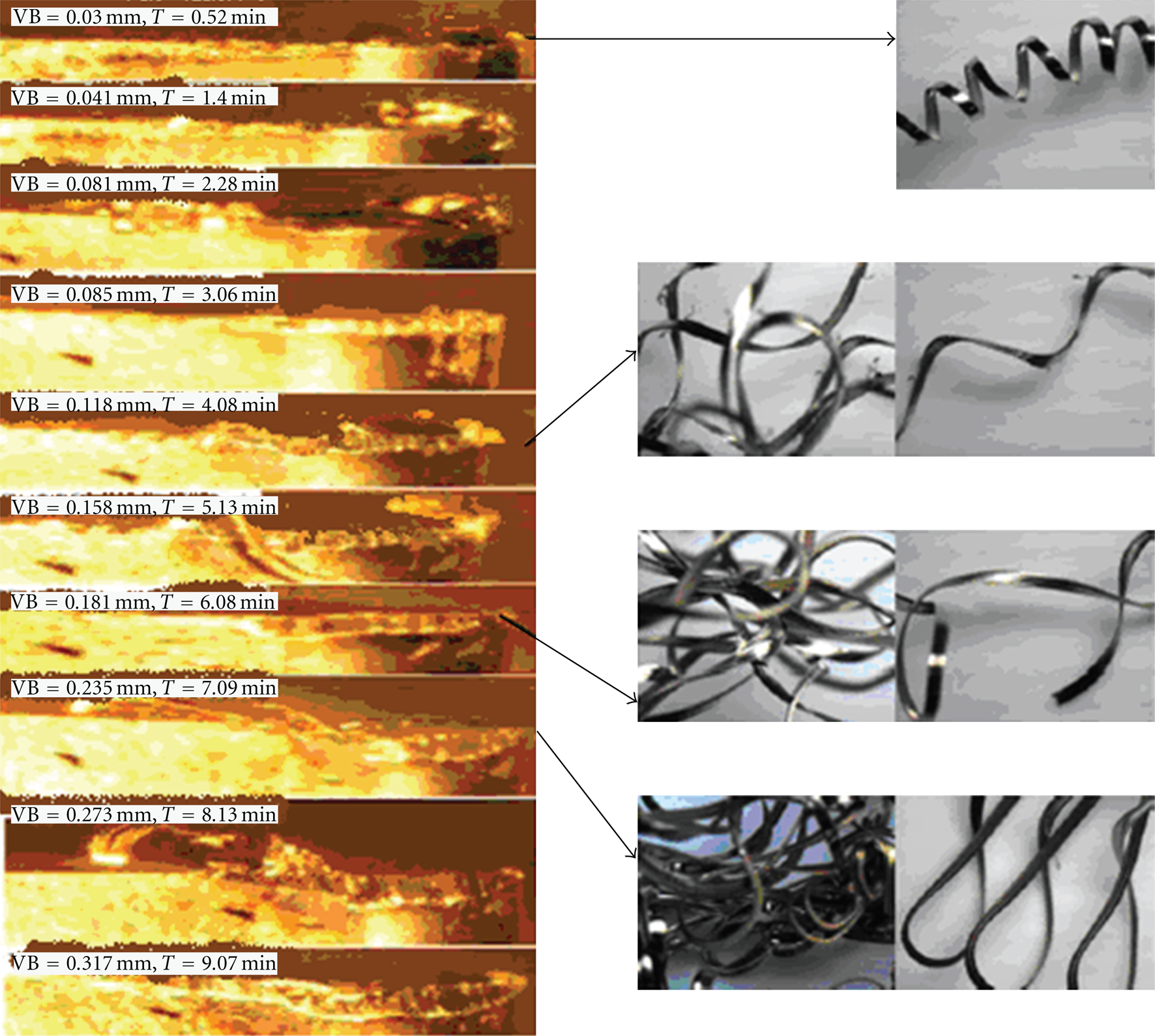
The flank wear progression steps when cutting speed was 70 m/min, feed rate was 0.20 mm/rev, and depth of cut was 0.50 mm and Types of chip produced.
The welded Inconel occurred at the cutting edge of tool because of the characteristics of Inconel 718 which reacts with the cutting tool at high temperature. which Similar to previous researcher found that operating at low cutting speed and low depth of cut can cause a chip stick on the cutting edge [7]. Operating at low cutting speed generates a low temperature between the cutting tool and the chip, so that this temperature is not high enough to release the chip from the cutting edge, as shown in Figure 3 at stage 2. Similar phenomenon was also found when machining titanium alloy, as reported by Che Haron et al. [15], that machining titanium alloy used cemented carbide tool under dry cutting condition, there was a strong bonding between the chip and tool material. Generated temperature was high, this condition was conducive for adhesive wear; therefore, rough machined surface will be produced.
At the initial cutting, machining of Inconel 718 produced a regular of continuous helical chip formation due to Inconel 718 being the material that consist of more than two phase. Then, chip formation changed to nonregular continuous chip and grouping. The changing of chip formation was caused by change of wear progression of the cutting edge of tools. At the end of machining, the color of chip changed to red grey. It was due to very high temperature generated while machining mainly at the interface between cutting tool and chip.
Similar to the phenomenon at Figure 3, Figure 4 shows a flank wear progression steps at the second area of machining at cutting speed of 70 m/min, feed rate of 0.30 mm/rev, and depth of cut of 0.40 mm. Some material of Inconel adhered or welded on the rake face and the cutting edge of tool. Small amount of titanium alloy is welded on the cutting edge when VB reached 0.119 mm. Further machining caused welded material to remove away from the cutting edge. According to Konig [16], the adhered or welded workpiece material on the cutting tool occurred when machining super alloy materials due to low generated temperature when machining at the low cutting speed.
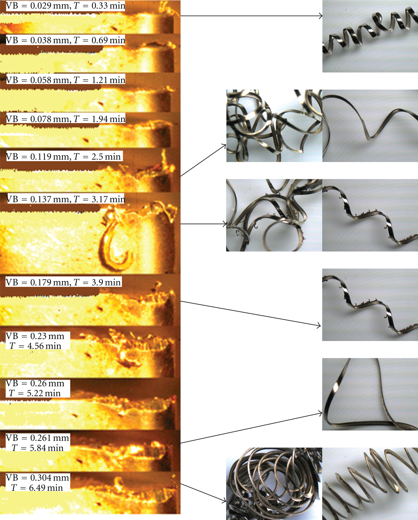
The flank wear progression steps when cutting speed was 70 m/min, feed rate was 0.30 mm/rev, and depth of cut was 0.40 mm and types of chip were produced.
3.4. Wear Mechanism
Wear mechanism occurred when turning Inconel 718, using PVD-coated carbide tool at various cutting speeds, feed rates, and depths of cut as shown in Figure 5. Abrasive wear on the flank face and the rake face, coating delamination at initial wear (at the flank wear), flaking and adhesive wear at the rake face, crack and fracture at the cutting edge. Adhesion or adhering chip of the cutting edge of Inconel material can be seen clearly, demonstrating a strong bound (no evidence of any gaps) at the workpiece tool interface. According to Konig [16], the adhesion wear takes place after the coating has worn out or coating delamination has occurred. The adhered or welded super alloy materials will be hit and squashed by the tool, and reentered the workpiece, thus leading to the initiation of chipping, flaking, and finally to the breakage of carbide at the cutting edge or fracture. Previous researchers have reported on phenomenon of coating delamination that when machining using coated carbide tool, delaminated coating performed before severe worn out or fracture. Some of them have attributed to chemical reaction, whereas others have argued that it is due to crack propagation at the surface interface, which could be due to the difference in the thermal coefficient of expansion between coating matrix and the substrate [7, 17]. The abrasive wear was due to the presence of hard particle and impurities and the adhesion wear was due to high temperature generated when machining Inconel 718 which caused welding to take place between the surface of chip and the tool rake face [7].

The tool wear mechanism with machining Inconel 718 at various cutting speed, feed rate, and depth of cut under dry cutting condition.
4. Conclusions
The most significant factor that influences the flank wear or tool life at high cutting speed and dry machining is depth of cut followed by feed rate and cutting speed, respectively. Tool life is significantly influenced by temperature generated at the cutting zone when machining Inconel 718 under dry cutting condition. Increaseing the cutting speed and depth of cut affected the tool life and promoted wear progression. At the first stage, the wear increases rapidly, then a chip that welded is at the cutting edge of the tool, and almost at the end of tool life, severe chipping at the cutting edge occurred due to machining at high cutting speed and coupled with brittle characteristics of Inconel 718. Wear mechanism types of carbide tools when machining Inconel 718 under dry cutting condition are abrasive wear on the flank face and the rake face, flaking and adhesive wear at the rake face, crack and fracture at the cutting edge.