
Abstract
At present day, pipe mill engineers have to deal with challenging technological problems of heavy-wall and high-strength line pipe manufacturing. Numerical analysis of welded large-diameter pipe manufacturing stages is the most efficient way to solve these problems. Corresponding computational technologies and applied software were developed at Physical & Technical Center. Numerical structural analysis of steel plates at various stages of line pipe manufacturing is performed by the finite element method, accounting for geometric and material nonlinearities. The only thing to be done by the engineer in such analysis is to specify required input parameters. All the further process is software controlled. The discrepancy between the numerical analysis results and measured data in the overwhelming majority cases did not exceed 1%.
1. Introduction
The fast growth of energy consumption in the world guaranties a stable growth of demand for welded large-diameter pipes, which are used in the construction of oil and gas trunk lines. Most of such pipes are made from steel plates by the so-called UOE process. UOE stands for a series of three basic steel plate forming processes in pipe manufacturing: U for forming the steel sheet to the U-shape (U-ing), O for forming the U-shape to the O-shape (O-ing), and E for expanding the formed and welded pipe to the specified diameter (expansion). The characteristic feature of this process is elastic-plastic deformation of cold steel plates at each process stage. In addition, longitudinal welding is accompanied by the formation of hot spots in pipe walls. Thus, each manufactured line pipe possesses some nonuniform residual stress state. Such residual stress state determines the key measures of pipe quality, such as deviations from specified diameter and specified wall thickness, out-of-roundness of cross-sections, straightness of longitudinal sections, end squareness, and so forth.
A large number of trans- and intercontinental trunk lines are being constructed today for oil and natural gas transmission. Such trunk lines contain a large number of segments, which are laid in tough locations. Such tough locations include, first of all, high-mountain and seismically active regions, permafrost regions, seas, and oceans. In order to meet applicable safety standards, pipeline system segments laid in critical areas are usually assigned higher design safety margins. In addition, pipes supplied for the construction of such segments are subject to more stringent standard dimensional requirements. In order to satisfy such strict dimensional standards, pipe mill engineers have to deal with challenging technological problems. On one hand, in order to provide higher strength of line pipes, one has to increase their wall thickness and/or use steel plates from high and ultrahigh strength grades of steel. On the other hand, in manufacturing high-strength heavy-wall pipes, one has to ensure their compliance with standard dimensional requirements. For example, for the installation of subsea pipeline systems, one has to use large-diameter pipes with a wall thickness of up to 50 mm made from steel grades up to X120 inclusive. Dimensional deviations of line pipes from specified values should lie within strict standard tolerance ranges. As an illustration, Table 1 presents the values of such tolerances for major dimensional characteristics of submerged arc-welding line pipes [1].
Standard dimensional requirements for line pipe with a diameter of D≥610 mm and wall thickness of t≥20 mm.

Notes: D = specified outside or inside diameter; t = specified nominal wall thickness; L = pipe length.
Numerical simulations for the analysis of large-diameter pipe manufacturing operations offer the most efficient way to solve challenging technological problems in pipe manufacturing and to provide compliance with strict quality standards. In order to carry out automated numerical analysis of the complete manufacturing cycle of welded large-diameter pipes, Physical & Technical Center has developed corresponding computational technologies and applied software.
2. Mathematical Models and Numerical Analysis Techniques Employed
Analysis of multiaxial stress state of steel plates at different stages of line pipe manufacturing is provided for the numerical solution of the governing solid mechanics equations accounting for geometric and material nonlinearities [2–4]. Structure velocities at process stages in pipe manufacturing are not high. Therefore, inertia effects can be ignored, and the problem can be reduced to a quasisteady-state case, or solution of equilibrium equations. The most convenient way of solving the equilibrium equations is the direct displacement method. Given the substantially higher stiffness of press tools compared to the stiffness of steel plates, the tools can be represented by rigid bodies. The laws of spatial tool motion can be used conveniently as boundary conditions. In this case, force action on steel plates is simulated by a set of contacts at interfaces between die, steel plate, rollers, and other equipment components. One should also note that in order to obtain accurate results, simulations of most of process stages in pipe manufacturing should include gravity effect.
Physical nonlinearity of steel plates is described by constitutive models of the incremental theory of plasticity for elastic-plastic hardening materials [2, 3]. Strain rates of the steel plate material at process stages in large-diameter pipe manufacturing are not high either. Therefore, rate-independent plasticity models are sufficiently suitable for most of such process steps, except the pipe welding processes. In order to provide credible numerical analysis of welding operations, one should also account for the rate-dependent properties of material, namely, the short-term creep of steel at high temperatures [5].
Numerical structural analysis of steel plates at various stages in line pipe manufacturing is performed by the finite element method [6–8]. As a numerical simulation tool, it is reasonable to use general-purpose FEA programs possessing the required functional features. Note that recent versions of the most widely used general-purpose FEA programs (ANSYS, ABAQUS, LS-DYNA, MSC.NASTRAN, MSC.MARC, COSMOSM, etc.) offer such capabilities. In all the above software, FEM has been implemented by solving a weakly stated variationalproblem of deformable solid mechanics by the displacement method [6, 7]. Below we describe algorithmic procedures realized in ANSYS environment [9] and present some results of numerical analysis of process stages in large-diameter pipe manufacturing obtained using these procedures.
As a rule, detailed multiaxial stress state simulations require 3D FE-models of steel plate (pipe) and tools. 3D FE-models enable successive numerical analysis of all pipe manufacturing processes and give as a result the nonlinear stress state of large-diameter pipes accounting for the effects of each process. When only 3D FE models are used, the residual stress state in a manufactured large-diameter pipe is determined taking into account the effects of each process by performing a series of numerical simulations of all pipe manufacture processes with the same model. No special procedure for mapping the state variables from one process to the other is required in this case. The drawback of this approach is that it requires using high-performance supermini computers or multiprocessor clusters with a large RAM size and disk space. However, for some stages, such as forming (Figure 1), it is quite reasonable to assume that the strain state of the cross-section of a long pipe is plane. Therefore, numerical analysis of such process stages can also be performed using 2D FE-models of steel plate and tools. 2D FE-models efficiently save computational resources, which are required for producing apractical result, thereby enabling optimization of line pipe manufacturing processes on standard personal computers. When 2D FE models for forming processes and 3D FE models for welding, expansion, and hydrostatic test processes are used in combination, it is impossible to account for the effects of the forming process on the residual stress state of a finished large-diameter pipe to the full extent. In this case, 3D FE models are constructed taking into account only the simulated open-seam pipe cross-section geometry generated using 2D FE models.

U-ing of steel plate.
3. Automated Numerical Analysis of Large-Diameter Pipe Manufacturing
3.1. Computational Technology
The process of welded large-diameter pipe manufacturing is a sequence of the following basic stages: forming, longitudinal welding, expansion, and hydrostatic testing. Each basic stage, in turn, comprises a set of process steps with variation in the multiaxial stress state of steel plate (pipe). Therefore numerical analysis of process is divided into respective successive simulation steps, which reflect the loading history of the pipe structure.
As noted above, in order to simulate the nonlinear behavior of a steel plate under mechanical loading, we use the elastic-plastic hardening material model. In this case, steel should be simulated as an elastic-plastic material with kinematic or combined (translation and expansion of the yield surface in stress space with progressive yielding) hardening law. In this material model, one can take into account the Bauschinger effect, which manifests itself noticeably in low-alloyed steel grades in the repeated loading-unloading cycles typical of large-diameter pipe manufacturing processes [10]. Application of this model to the nonlinear metal behavior analysis also makes it possible to obtain satisfactory results even with a minimum set of initial data. For example, in order to plot a bilinear stress-strain curve for an elastic-plastic material with the kinematic hardening law, it would suffice to know standard characteristics of physical and mechanical properties of steel and ultimate strain εUTS that corresponds to ultimate tensile strength (UTS) in the strain-stress diagram. Then, stress values beyond the yield stress can be calculated as

where E is Young's modulus; σ
Y
is yield stress;
The size of a computational model is determined based on the minimum length of finite elements discretizing the steel plate in the through-the-thickness direction. In order to achieve the required accuracy of simulations on PCs, the size of FE meshes through the plate thickness should be 6 to 12 for 2D FE models and 2 to 4 for 3D FE models. The complete FE mesh is then generated subject to the condition that the FE aspect ratio should not exceed 1 : 4 and that the fine-to-coarse mesh transition should be gradual. For adequate simulation of each process, defined boundary conditions should not constrain real degrees of freedom of the steel plate/pipe. Therefore, in most cases, such conditions are limited to the fixed pipe supporting rollers and displacements/rotations of the tool. All nodes of the FE pipe model remain unfixed during numerical analysis and stay in equilibrium only due to friction at the interface with adjacent equipment components. Such an approach significantly complicates the process of obtaining the nonlinear solution, but represents the actual stress state of the structure with the highest possible accuracy. Corresponding efficient algorithms for obtaining converging solutions of nonlinear contact problems with multiple repeated loading have been developed and implemented in the computational technology for each large-diameter pipe manufacturing process [10].
Open-seam pipe is made using the UOE technology on forming presses. The forming process usually consists of three process steps: edge crimping, U-ing (Figure 1), and O-ing. In the first forming stage, the plate is crimped in the area of its longitudinal edges. The method of U-ing and O-ing and respective tools depend on the type of welded pipes to be manufactured. The two types of large-diameter pipe, the manufacture of which is particularly widely spread today, include single-seam and double-seam pipes. In the latter case, the last process step is called C-ing, because the resulting half of pipe has a C-like shape. Numerical simulation technologies for open-seam pipe forming have been implemented for both single-seam and double-seam types of large-diameter pipe. Figure 2 represents successive numerical analysis of double-seam pipe forming stages. The successive implementation of all forming processes with the same FE steel plate model shown in Figure 2 makes it possible to obtain the nonlinear residual stress state of a half pipe taking into account its complete loading history during the forming processes.

Continuous numerical analysis of double-seam large-diameter pipe forming stages (2D FE models): edge crimping (a), U-ing (b), and C-ing (c). Von Mises stress (Pa) pattern in the steel plate.
An alternative to UOE is the JCOE process developed in recent years by SMS MEER GmbH [11]. In the JCOE process the plate, milled and crimped at the edges, is fed step-by-step by manipulators to the forming tool in the pipe forming press where it is formed over the whole plate length: J-ing, C-ing, and O-ing. E stands for expansion, just as before. The major advantage of the JCOE process is the possibility of making heavy-wall (t≥35 mm) pipe of any diameter, including relatively small diameters without any increase in capacity of forming presses. The demand for different-size heavy-wall pipes increases rapidly as a result of large-scale installation of offshore trunk lines all over the world. As most of Russia's line pipe manufacturers use forming equipment supplied by SMS MEER, special attention in the computational technology developed by the Physical & Technical Center is paid to the algorithms enabling highly accurate simulations of the JCOE forming process. Figures 3 and 4 show examples of numerical simulation results for JCOE forming. Note that edge crimping is also performed step-by-step with longitudinal die motion. As one can see in Figures 3 and 4, the nonlinear stress state resulting from JCOE forming is essentially nonuniform in both longitudinal and transverse sections of the steel plate.

Von Mises stress (Pa) pattern in the steel plate at the first step of edge crimping, tool are not shown (JCOE process, 3D FE model).

Von Mises stress (Pa) pattern in the steel plate at the 16th forming step (JCOE process, 2D FE model).
The as-formed open-seam pipe is fed to the roller cage, where pipe edges are pressed together and tack welding is performed. The tack-welded pipe is then conveyed to the submerged-arc welding stand where, at separate lines, it is provided first with the inside and then with the outside pass. In the computational technology, elimination of offset between pipe edges is simulated in accordance with the respective process stage. At the same time, all computational solid mechanics, thermodynamics, and electrodynamics models, which describe interrelated complex physical processes in metal welding operations, cannot be implemented in numerical simulations without supercomputers. In addition, most of such computational models are still in the phase of their development and validation. Therefore, for the purpose of computational implementation of continuous numerical analysis of the line pipe manufacturing process flow, simulations of longitudinal welding were restricted to solving a coupled thermal-stress problem. The latter is quite sufficient for consistent multiaxial nonlinear stress state modeling accounting for thermal strain of pipe. The thermal-stress problem is solved in two interrelated successive steps: transient thermal analysis of the nonuniform temperature field in pipe walls accounting for the given heat input, radiation, and convection heat exchange with surrounding medium, and structural analysis of multiaxial stress state accounting for the transient temperature field. The rate of short-term creep of pipe material was evaluated using the relationship

where σ is stress, T is temperature, and C, n, kare material constants. It is also necessary to add that welding simulations should account for the temperature dependence of all characteristics of physical and mechanical properties of pipe steel. Figure 5 shows examples of numerical simulation results for thermal-stress analysis of the line pipe welding process. Figure 5(a) shows the nonuniform temperature pattern in the upper half of a single-seam pipe after its welding and cooling to 370 k. As shown in Figure 5(a), some noticeable temperature effect is produced in a limited region along the longitudinal weld seam. The width of this region is generally no larger than 5 to 10% of the pipe perimeter. Note that the temperature distribution in the transverse (hoop) direction of such a region is essentially nonlinear (Figure 5(a)). Therefore, thermal and mechanical effects on the pipe as a result of welding show as a fairly narrow band of residual strain (Figue 5(b)), which leads to the banana-shaped longitudinal distortion of the pipe.

Results of numerical thermal-stress analysis of pipe welding: temperature (K) pattern in the seam region, 1080 seconds after welding completion (a); equivalent creep strain pattern in as-welded pipe (b).
The as-welded pipe is not yet able to satisfy the tolerance specifications in relation to diameter, roundness, and longitudinal straightness. In the finishing department, therefore, it is sized by cold expansion. This operation is performed by hydraulic or mechanical expanders. The computational technology contains models for both types of pipe expansion. An example of numerical analysis of mechanical pipe expansion is depicted in Figure 6. As evidenced by Figure 6, on the one hand, mechanical expansion effectively straightens the pipe geometry. On the other hand, this process also results in a noticeable redistribution of the multiaxial nonlinear stress state in pipe walls, making it significantly more nonuniform. The final stage in the line pipe manufacturing process is hydrostatic testing. The comparatively low hydrostatic test pressure cannot have any significant effect on the dimensional parameters of pipe. However, in order to obtain a highly accurate pattern of stresses in pipe, a simulation capability for such load was implemented in the computational technology as well. Figure 7 shows an example of residual stress pattern in large-diameter pipe body after hydrostatic testing. If we carefully examine the stress field in pipe walls in Figure 7, we will see a narrow region along the longitudinal seam, where maximum stresses occur. Such a pattern of residual stress state is due to the modern technology of making welded large-diameter pipes and is typical of all the above forming methods. Note that this kind of information is necessary today for high-accuracy numerical analysis of remaining strength of pipeline systems accounting for all factors, including residual stresses in line pipes [12].

Von Mises stress (Pa) pattern in pipe wall at the 10th step of mechanical expansion (1/2 of FE model).
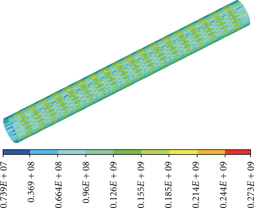
Residual stress state of pipe after hydrostatic test, Von Mises stress (Pa) pattern.
3.2. Industrial Application and Verification
The computational technology described above is intended for unassisted industrial application by engineers of the pipe manufacturing industry. Physical & Technical Center has therefore developed algorithms, procedures, and applied software enabling automated numerical analysis of the full cycle of making a certain type of large-diameter pipe. In particular, with ANSYS used as a solver, the developed applied software comprised two parts: a kernel in the form of a library of modules written in the APDL (ANSYS Parametric Design Language) macro language and a graphical user interface written in Microsoft Visual C++. The only thing to be done by the engineer in such analysis is to specify required input parameters (or choose them in attached databases), such as the pipe size, physical properties of the steel plate material, tool parameters, and so forth. All the further process of FE-model generation, assignment of boundary conditions and application of loads, choice of nonlinear analysis options, and processing of numerical simulation data is software controlled. This approach facilitated efficient assimilation and application of the computational technology by pipe mill engineers.
In their turn, in learning how to operate the computational technology, industrial engineers carried out its extensive verification by comparison of numerical simulation results with actual parameters of manufactured large-diameter pipes. An example of such verification is shown in Figure 8. In this Figure, values of the polar radius of an as-formed double-seam large-diameter half pipe measured (red curve in Figure 8(b)) by a high-precision optical device (Figure 8(a)) are compared with the results of numerical analysis using the above computational technology and applied software (blue curve in Figure 8(b)). Figure 8(b) shows that the simulated and measured values are in close agreement. Note that the discrepancy between simulated and measured data in the overwhelming majority of such verification cases did not exceed 1%.

Verification of the computational technology: high-precision optical measurements of a half of double-seam pipe after U-forming (a); comparison of measured data and numerical simulation results (b).
4. Conclusions
The computational technology for numerical simulation of the full cycle of large-diameter pipe manufacturing operations presented here is an efficient tool, which helps improve the competitiveness and broaden the product range of pipe mills. Industrial application of this technology allows pipe manufacturers to save time spent on setting up commercial production of highly demanded heavy-wall pipes from high and ultra high strength steel grades, which comply with strict requirements of international standards. At present, the computational technology is used in a number of large Russian pipe manufacturing companies.