
Abstract
This work evaluates the hole quality on AISI H13 hardened steel using high-speed drilling. Specimens were machined with new and worn out drills with 8.6 mm diameter and (TiAl)N coating. Two levels of cutting speed and three levels of cooling/lubrication systems (flooded, minimum lubrication quantity, and dry) were used. The hole quality is evaluated on surface roughness (Ra) parameter, diameter error, circularity, and cylindricity error. A statistical analysis of the results shows that the cooling/lubrication system significantly affects the hole quality for all measured variables. This analysis indicates that dry machining produces the worst results. Higher cutting speeds not only prove beneficial to diameter error and circularity errors, but also show no significant difference on surface roughness and cylindricity errors. The effects of the interaction between the cooling/lubrication systems, tool wear, and cutting speed indicate that only cylindricity error is influenced. Thus, the conclusion is that the best hole quality is produced with a higher cutting speed using flooded or minimum lubrication quantity independent of drill wear.
1. Introduction
Nowadays, the molds and dies industries are very important in the supply chain to obtain a new product at low costs. In addition, considering industrial competitiveness and short product life, the requirements on production times and lower costs of machining processes are of significant importance. One should also consider that drilling is an especially extreme process in most industries, which use conventional machine tools the majority of times. When the production of molds and dies is considered, the machining process corresponds to 65% of the costs and drilling is the most utilized process. According to Haber-Haber et al. [1], drilling is one of the main machining operations in the manufacturing industry, and in some countries drilling has been reported to account for nearly 50% of all machining operations.
That is why it is important to study drilling performance with strong reduction or total elimination of cooling systems, considering the aspects of tool life. Cooling fluids are very important in high-speed cutting where the temperature can approach annealing point. Heat generation and friction between the tool and chip generally limit drilling performance, therefore coolants and lubricants are used in high quantities to reduce the temperature and friction in the cutting region [2].
On the other hand, vapors generated during the machining process are prejudicial to the operator's health, and much research has been carried out aiming to reduce the use of fluids. For this reason, and in some specific cases, the use of minimal quantities of lubrication is a solution that can be implemented, like in plain carbon steel drilling where this technique is a good alternative between dry and flooded machining [3].
Tool wear has always been a problem, due to the need to stop the machining process in order to change the tool, meaning additional costs and lost productivity. Drilling is affected, just as machining in general, by tool machine rigidity, tool wear, and other factors that directly influence the hole quality, causing dimensional, eccentricity, and form errors. The effects of tool wear on the surface roughness of holes have been studied by Sharmann et al. [4]. They used drills with eight different geometries to drill Inconel 718, and the results show that for two geometries, the surface roughness obtained with the worn out drill was significantly smaller than those obtained with new drills. In other cases, the difference was negligible.
The development of coatings allow the use of tools in extreme machining conditions, because, if applied correctly, they increase the tool's surface hardness and minimize the effect of abrasive wear under high temperatures by reducing the friction coefficient between tool and hole [5]. Aneiro et al. [6] have studied tool wear and the influence of coating on the reduction of friction in the turning of hardened steels. They note that coated tools show significant effect minimizing heat and friction due to its low adhesion coefficient. Moreover, during the experiments the temperature was monitored using an embedded thermocouple showing that tests with coated tools generated the lowest values.
The interaction of cutting speed and tool coating on the integrity of the hole surface has also been the object of study, and according to Tosun and Muratoglu [7] the cutting speed increases the roughness surface of holes drilled with TiN coating in Al/SiCp composites. This occurs due to the great chemical interaction between composite and coating and with high-speed drilling this effect is harmful to the tool.
Cooling/lubrication plays an important role in tool wear because cutting fluids fulfill multiple functions simultaneously in a machining process: cooling and lubrication of the tool/specimen interfaces and chip/tool interfaces, the extraction of chips of the cutting region, the prevention of edge formation, among others. However, the costs of cutting fluids are increasing due to environmental concerns related to fluid handling, disposal, and the coming legislations from national and international authorities [8–11].
According to Nandi and Davim [12], two techniques to eliminate cutting fluids in machining processes have proven successful. The first one is dry machining. In this case, it is essential to use suitable tool materials and cutting conditions to avoid a large decrease in tool life and the loss of specimen quality. The second method that can diminish the amount of cutting fluid in the machining process is the use of minimum quantities of lubricant. Brandão et al. [13] show that the effects of heat can be minimized with the use of cooling with a minimum quantity of lubricant. The finite element analysis shows that this system has the same ability to remove heat from the machining process with a smaller amount of cutting fluid. This work evaluates the influence of different cooling/lubrication systems on the drilling process of hardened steels with high-speed cutting. This study takes the influence of variables such as new and worn out drills on hole surface roughness into consideration.
2. Methodology
The goal of this work is to evaluate the interaction between cutting speed and tool wear on hole quality and to describe its quality with a statistical methodology obtained by a complete randomized factorial design. This design of experiments was developed using the cooling/lubrication system, the cutting speed, and the drill's flank wear as input variables, and the Ra surface roughness, the diameter error, the circularity, and the cylindricity error as output variables. The cooling/lubrication system was evaluated on three levels; dry, flooded, and minimum quantity of lubricant. Cutting fluid applied on both systems was BioG 850, mineral-based oil, viscosity 18 cSt at 40°C, produced by Microquímica. The MQL system was set for 20 mL/h, both with integral mineral oil. The cutting speed was evaluated on two levels; 25 and 60 m/min, which correspond to the minimum and maximum values according to the supplier recommendation, and the drills were evaluated on two levels; new and worn out. A fourth variable was used only to evaluate the diameter error, on two levels: hole top and bottom.
Each test received a sequential identification number, so the tests sequence was completely randomized; Table 1 shows a summary of the experiment design. Figure 1(a) shows the plate used to generate the wear on the drills, and Figure 1(b) the specimen's layout used to measure the cylindricity and roughness of holes. The holes’ assembly according to the scheme of Figure 1(b) was done with the objective of maximizing the number of holes on the specimen.
Summary of the experiment design.


Details of the specimen used in drilling tests.
A ROMI machining center, model Discovery 560, with 7,500 rpm and 15 kW of spindle power was used. The machining trials involved drilling the AISI H13 specimen (100 × 40 mm and 14 mm thick, Figure 1(b)) with 53 HRC and the following average chemical composition: 0.40% C, 0.95% Si, 0.31% Mn, 0.011% P, 0.006% S, 5% Cr, 0.12% Ni, 1.25% Mo, and 0.13% Cu. The holes were drilled with Alpha-Rc tools model A3269TFL ∅8.6, helix length = 47 mm and total length = 89 mm, according to DIN 6537K, Figure 2(a).
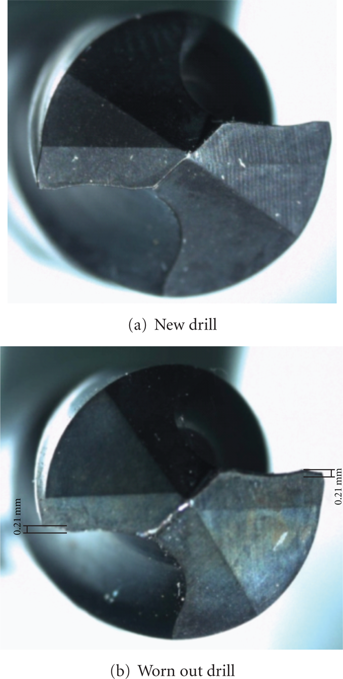
Detail of the cutting edges for new and worn out drills.
Preliminary tests were carried out on the AISI H13 specimen as can be seen in Figure 1(b), with the aim of generating holes with diameters within 8.6±0.02 mm with a new drill. This way it was possible to evaluate hole quality at the start of experiments. In order to increase the tool wear, successive tests were carried out on the other plate, as can be seen in Figure 1(a), with the same chemical composition of the specimens until the flank wear reach 0.21 millimeters, which corresponds to the average value of tool wear during drilling tests, Figure 2(b). The tool wear out above 0.21 occurred at the end of the cutting edge, and the probability of breakage of the tip could lead to uncertain data during the tests affecting the results. Thus, the value of 0.21 was considered as pattern to define the end of the experiments.
Form errors were measured in a Tailor Robson device, model Talyround 131, using an accuracy of 5 and 10 measure points in the axial direction for cylindricity error, and an accuracy of 0.5 μm with 36 radial points for circularity errors, as can be seen in Figures 3(a) and 3(b), respectively.
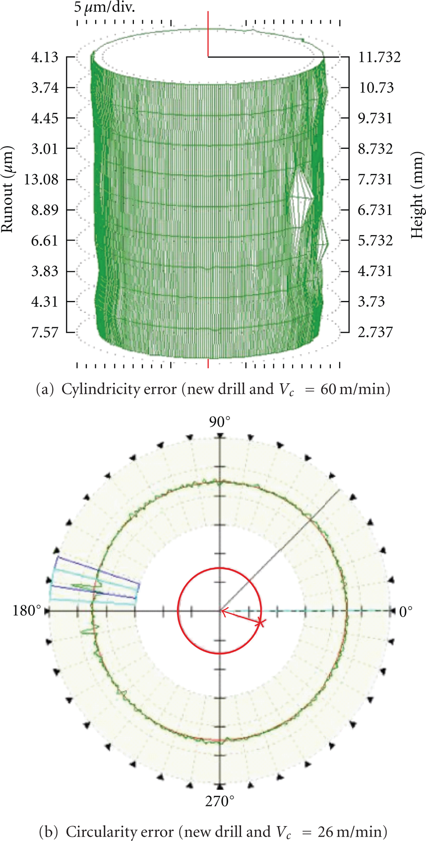
Detail of cylindricity and circularity errors.
3. Results and Discussion
3.1. Roughness
Figure 4 shows the average roughness values on the hole wall as a function of the input variables. With the minimum quantity of lubricant, the roughness surface values are high for the worn drill running at 60 m/min and low for the new drill running at 25 m/min. The flooded coolant system shows very similar results with medium roughness surface values of 0.35 mm, dry tests show high values for the new drill running at 60 m/min and small values running at 25 m/min for the worn drill. Thus, the minimum quantity of lubricant is more effective only with the new drill running at 25 m/min because when high cutting speed and worn out drill are applied, the spray generated during the process loses its effectiveness, not cooling the cutting region.

Mean roughness × input variables.
The use of flooded system does not represent an efficient drilling solution. The roughness surface values for this condition remain near those for minimum quantity of lubricant, but the resulting waste in coolant fluids is very high. It demonstrates that hole quality using excessive cutting fluid does not change and does not produce a good surface. The dry condition shows the worst values for roughness surface and significant differences only do not occur, because the worn drill with cutting speeds of 25 mm/min shows a value below of 0.5 μm.
A variance analysis (ANOVA) with 95% reliability is shown in Table 2, where SS is a square sum, F is the calculated variance, and F0 is variance from a Fisher distribution. H0 is the null hypothesis that holds that the treatment means are equal. According to ANOVA, the cooling/lubrication system influences hole wall roughness. New or worn drills do not significantly influence roughness Ra of the holes and neither do cutting speeds. Therefore, there is no interaction between the variables, except in the case of cooling/lubrication system and new or worn drill. Instead tests show that the dry system produces hole wall Ra roughness values higher than the other systems. There is no difference, however, between MQL and the flooded system. The worst interaction occurs with the dry cooling/lubrication system using new drills, and the best interaction occurs with the MQL cooling/lubrication system combined with new drills.
Analysis of variance to wall roughness Ra.

3.2. Diameter Variation
Specimen hole diameters were measured in radial positions at 120° at the beginning and end for each cutting speed. Thus, the diameters medium values were obtained and correlated to the trials with the cooling/lubrication systems and dry condition. Figure 5 shows the mean results of the drilling. Figure 5 shows that no tendency can be inferred from the results using a statistical analysis with a variance of 95% reliability, corresponding to Table 3. According to our analysis, the diameter variation is affected by cooling/lubrication system, cutting speed, and drill condition.
Analysis of variance for diameter error.


Diameter error × input variables.
Regarding diameter error, contrast testing indicates that flooded cooling/lubrication and MQL system produce the same results. The dry system shows the largest diameter error, where new drills produce worse results than the worn drills, and high cutting speed prove to be better at reducing diameter error. In addition, the results show that worn out drills using flooded cooling/lubrication systems and high cutting speeds produce holes with smaller diameter error.
3.3. Cylindricity Error
Figure 6 shows the mean results for cylindricity error of the drilling trials. The cylindricity error corresponds to a three-dimensional geometric tolerance that controls how much a feature can deviate from a perfect cylinder. From Figure 6, one can conclude that the worn drills produce higher cylindricity error and that the cooling/lubrication system demonstrates important differences in the outcome.

Cylindricity error × input variables.
The variance analysis with 95% reliability is presented in Table 4, and shows that the cooling/lubrication system and the drill condition are of great influence on cylindricity error. Cutting speed, on the other hand, has no influence on cylindricity error. Table 5 shows the contrast test for cooling/lubrication system and verifies that the systems produce different results and cylindricity errors minors. The same test was done on drill condition and shows that the worn drills produce higher cylindricity error. According to Figure 6, the lowest and highest values for cylindricity error are obtained with a cutting speed of 60 m/min, with the lowest using a new drill with flooded lubrication and the highest using a worn drill with the dry lubrication system.
Cylindricity error—analysis of variance.

Contrast test cooling/lubrication system—cylindricity error.

3.4. Circularity Error
Finally, circularity error is analyzed as a function of the input variables. The circularity error corresponds to a two-dimensional geometric tolerance that controls how much a feature can deviate from a perfect circle. Figure 7 shows the average results, and they show that MQL has the worst performance among the three systems providing the biggest circularity errors with a cutting speed of 25 m/min. On the other hand, the flooded system presents the best results in the average values, showing only great circularity errors for a cutting speed of 25 m/min with a worn drill.

Circularity error × input variables.
However, according to Table 6 the medium treatment values do not present a clear tendency. Using the variance analysis, however, clarifies the influence of the treatment on hole circularity error. Table 6 presents these results with 95% confidence.
Analysis of variance of the circularity error.
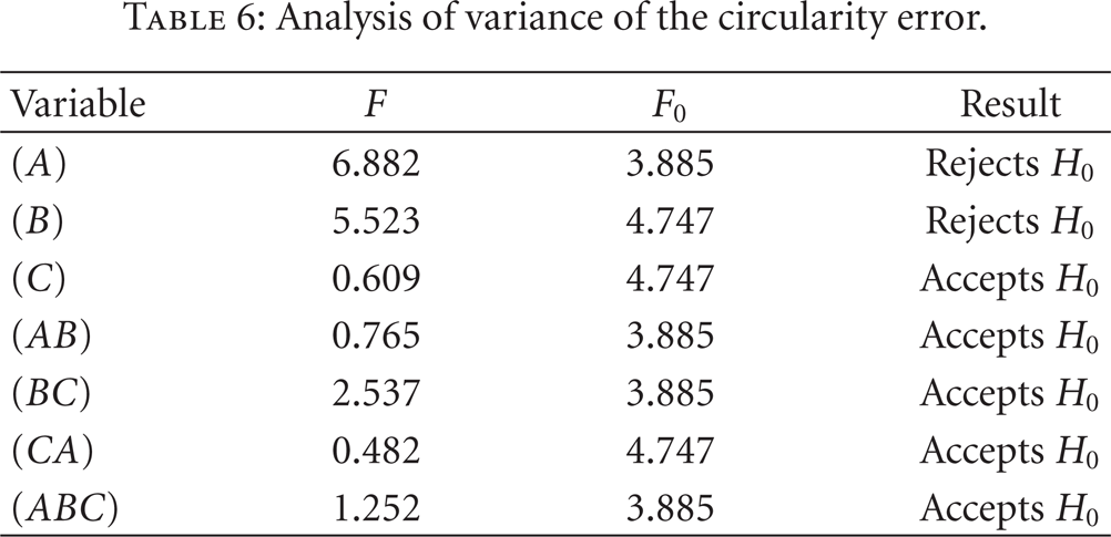
Table 6 shows that circularity error is affected mainly by the cooling/lubrication system and by the cutting speed, but it is not affected by drill condition. Table 7 shows the contrast tests only for cooling/lubrication system. This test was carried out with the objective of confirming the cooling system's influence on cylindricity error.
Contrast test for the influence of cooling/lubrication on circularity error.
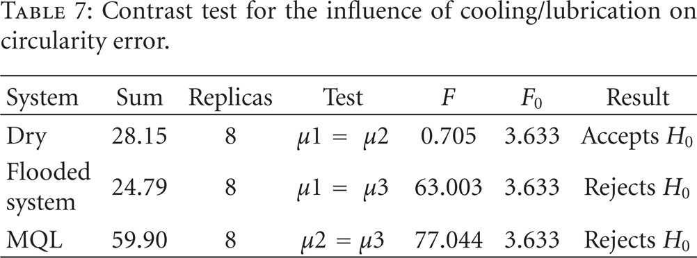
The results of Table 7 show that MQL and flooded systems produce similar values generating the worst results, and that the dry condition does not show significant influence. Conversely, the cutting speed reveals that high cutting speeds obtain the best results due to its ability to maintain the cutting mechanism and process kinematics, generating the best chip formation and not interfering directly with cylindricity error.
4. Conclusions
This study represents a stable effect model, thus the conclusions are based only for the new and worn out drill condition. Therefore, based on the results of this investigation the following conclusions can be drawn.
From the input variables studied, cooling/lubrication is the one that most affects hole quality. The dry system produces the worst results while the flooded system produces the best results.
The cutting speed on its own influences hole quality and the best results can be obtained using high speeds.
The measurement position of the hole diameter does not have a significant influence on the results.
Drill condition proves to be important for cylindricity error and diameter variation, because worn out drills produce better results on diameter variation and worse results on cylindricity error.
Circularity error, considering the results obtained only for the new and worn out drill condition, is affected mainly by the cooling/lubrication system and by the cutting speed, but it is not affected by the drill condition.
Since diameter variation is the most important variable to consider in hole qualifies, this study indicates that the use of flooded systems associated with higher cutting speeds and independent of drill condition produces the best results.
Footnotes
Acknowledgments
The authors would like to thank FAPEMIG for the financial support and the Laboratory for Optimization of Manufacturing Processes in São Carlos/USP for the technological support.