
Abstract
A method to synthesize a five-bar slider mechanism with variable topology is suggested. Synthesis is carried out in two phases for function generation. In Phase I, synthesis is carried out for three finitely separated positions. In Phase II, it is carried outfor two finitely separated positions. A dyadic complex number method is used to write the equations of motion. The method is simple, general and has an increased accuracy over graphical techniques. An application of the five-bar slider mechanism with variable topology is illustrated.
1. Introduction
Dimensional synthesis plays a vital role in kinematic synthesis of mechanisms. It deals with the determination of various link dimensions of mechanisms [1]. The variable topology mechanisms are used to meet complex motion requirements through multiple phases [2]. The main purpose of variable topology mechanism is to make synthesis processsimpler [3–5].
Four-bar slider crank linkages have been widely used in industrial applications [6]. Many works on five-bar linkages with variable topology mainly target on revolute joint type [3–5]. Though there are works which deal with the five-bar slider crank linkages, they are not commonly found in industries because of their limitations and difficulty in synthesizing [6]. The objective of the present work is to familiarize the five-bar slider mechanism for industrial applications and to make the synthesis of five-bar slider easy. For the purpose, a method known as variable topology is used. The paper deals with the synthesis of an offset five-bar slider with variable topology mechanism and a centric five-bar slider variable topology mechanism. In a way, this paper is the continuation of the work of second author [3–5]. The suggested procedure successfully applied tothe synthesis of five-bar slider which has not been tried.
The method used in the present work has been found in the previous studies for the planar five-bar and seven-bar mechanisms with only revolute pairs [3–5]. The mechanisms with sliders and so forth are not dealt with. Here is an attempt to use the technique to the mechanisms with prismatic pairs, that is, sliders, where the situations like that of offset slider and, hence, the stretch ratio come into picture.
1.1. An Offset Five-Bar Slider Mechanism
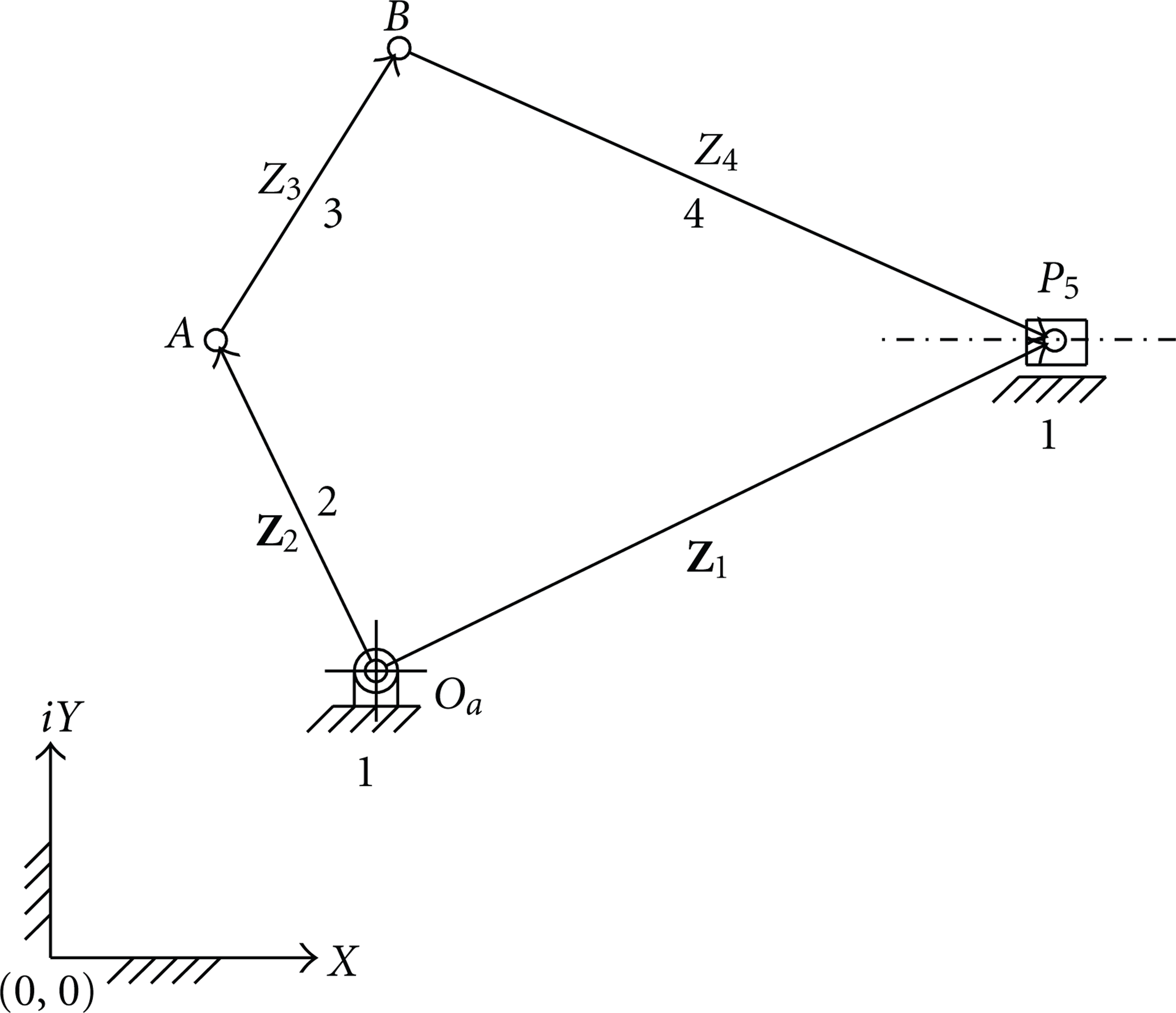
A planar offset five-bar slider mechanism has two degrees of freedom. It has one rotary and one linear independent input as shown in Figure 1. A planar five-bar slider mechanism with variable topology is a mechanism which operates as a simple single-degree-of-freedom mechanism in each phase.

AFive-bar slider mechanism.
During Phase I of operation, a link adjacent to the permanently fixed link, that is, crank O a A shown in Figure 2. is temporarily fixed which results in an off-set slider crank mechanism ABP of one degree of freedom. The synthesis procedure is then carried out for three finitely separated positions for the function generation task. The link lengths determined in Phase-I synthesis are considered while determining the remaining dimensions in Phase-II.

An offset five-bar slider variable mechanism with variable topology, Phase I.
In Phase II the slider is temporarily fixed in position 3, and the crank is released as shown in Figure 3. The resulting mechanism is a four-bar mechanism of single degree of freedom. Now the synthesis is carried out for two finitely separated positions for the function generation task to determine the other unknown parameters [3–5]. It is to be noted that the third position of Phase I is the initial position of Phase II.

An offset five-bar slider mechanism with variable topology, Phase II.
When the offset distance of an offset slider mechanism is reduced to zero, it becomes an in line or centric slider-crank mechanism as shown in Figure 4. The procedure of synthesis of mechanism in Phase I shown in Figure 5 is similar to an offset five-bar slider mechanism with variable topology except that the offset is equal to zero. Thus, this is a degenerated case of an offset slider-crank mechanism that is. it becomes a centric slider crank mechanism. The synthesis procedure is similar to an offset five-bar slider mechanism with variable topology. Hence, all the equations of Phase I of a centric five-bar slider mechanism with variable topology, are derived by setting the offset distance equal to zero in appropriate equations. The procedure of Phase II synthesis is similar because it is again a four-bar mechanism of single-degree freedom which is as depicted in Figure 6.
A centric five-bar slider mechanism.

Centric five-bar slider mechanism with variable topology, Phase I.

Centric five-bar slider mechanism with variable topology, Phase II.
1.2. Review of Literature
Stanely [7] suggests to couple any two adjacent links either rigidly or in some prescribed manner and reduce the five-bar loop to a four-bar linkage synthesis. Rawat [2] established a graphical synthesis technique for a five-bar variable topology mechanism operating in two phases. Joshi et al. [8] and Joshi [9] used the dyad synthesis for circuit breaker applications. Balli and Chand [3] dealt with synthesis of five-bar variable topology for motion between extreme positions, five-bar motion and path generators with variable topology for motion between extreme positions [4] and five-bar variable topology mechanism with transmission angle control [5]. Balli & Chand [10] proposed a method of synthesis of a seven-link mechanism with variable topology for motion between 2 dead center positions.
Kinzel et al. [11, 12] dealt with kinematic synthesis for finitely separated positions and function generation with finitely separated precision points using geometric constraint programming. Yan and Kang[13] dealt with configuration synthesis of mechanisms. Naik and Amaranath [14] studied synthesis of adjustable four-bar function generators through five-bar loop closure equations. Zhou and Ting [15] dealt with adjustable slider-crank linkages for multiple path generation. Zhou [16] dealt with synthesis of adjustable function generation linkages using optimal pivot adjustment. Deng-guise [17] dealt with analytical synthesis of slider-crank function generator with fifth order approximation.
Erkaya et. al. [18] dealt with dynamic analysis of a slider crank mechanism with eccentric connector and planetary gears. Vadasz [19] developed design charts for slider-crank mechanisms with prescribed minimum transmission angle and time ratio. Soylemez [20] dealt with Classical transmission angle problem for slider crank mechanisms using extreme positions. Zhou and Ting [6] dealt with the path generation with singularity avoidance for five-bar slider-crank parallel manipulators and categorize the five-bar slider mechanisms. Chen et. al. [21] dealt with synthesis of dyads with one prismatic joint. Du and Gou [22] presented the design of a new metal forming press with controllable mechanism using two inputs. Akyurt [23] used computer-aided graphical design procedures for the synthesis of basic linkages for input-output coordination for revolute pairs. Reifschneider [24] dealt with teaching Kinematic synthesis of linkages without complex mathematics i.e., by graphics based technique for the design of an offset-slider crank mechanism used for the oven door opening. Bagci [25] presented optimum synthesis of planar function generators by the linear partition of the dyadic loop equations. Gadad et. al. [26] presented combined triad and dyad synthesis of seven-link variable topology mechanism using a ternary link. Daivagna and Balli [27] dealt with the synthesis of seven-bar slider mechanism with variable topology for motion between two dead center positions with an application to press working operations. Daivagna and Balli [28] presented synthesis of an off-set five-bar slider mechanism with variable topology for finitely separated positions. Balli and Chand [29] explained variable topology mechanism synthesis as an advanced trend in mechanism synthesis.
1.3. Present Problem
The review of papers reveal that the synthesis of variable topology mechanisms are available for the revolute pairs only [3–5]. Many papers focus on the synthesis of single-degree-of-freedom mechanisms. The dimensional synthesis of a five-bar slider mechanism with variable topology is not dealt. The five-bar slider mechanism with variable topology may also be used to provide complex motion requirements in the industry [6].
Hence, the presentcase study deals with the five-bar slider mechanism with variable topology which yet not been studied [3–5]. Here, an offset five-bar slider mechanism with variable topology is synthesized. The synthesis of a special case, where in the offset is reduced to zero which resulting in an inline or centric slider-crank mechanism is also dealt with.
A variable topology synthesis method is suggested as an alternate method to the graphical method of synthesis suggested by Joshi et al. [8], Du and Guo[22]. Many methods of synthesis like algebraic method, loop closure technique and graphical methods, geometric constraint programming method, and algebraic methods are available for the slider crank mechanisms and four-bar mechanisms. The method of variable topology suggested in this paper reduces the cumbersome calculations of the algebraic methods. It has an increased accuracy over the graphical methods and graphics-based techniques. The main advantage of the method is that the two-degree-of-freedom mechanism is successively reduced to single-degree-of-freedom mechanism which involves only one input in each phase, thus, the complexity of the five-bar slider mechanism is reduced to that of single degree of freedom by operating it in two successive phases separately. The procedure is also applicable to seven-bar slider mechanisms with variable topology for function generation task.
2. Process of Synthesis
It is required to synthesize a planar five-bar slider with variable topology mechanism. One can have two options as follows:
one end, that is, the crank is fixed temporarily (Figure 2).
The slider is fixed temporarily (Figure 3).
The conventions to be followed to denote angles and link lengths in Phase I and in Phase II are described in Table 1. These conventions are used to write the dyad equations of the displacements of the slider for function generation. A function generation mechanism is a linkage in which relative motion transmissionamong links connected to ground is taken into account. It is required to coordinate the angular motion of the input link AB to the sliding motion of the output link, that is, the slider for three specified design positions [28, 29].
Conventions to be followed to denote the linkages and the angles in Phase I and in Phase II.

Note for sign conventions: Angular motion is positive for anticlockwise and negative for clockwise.
Linear motion of the slider is positive for left to right and negative for right to left.
2.1. An Offset Five-Bar Slider Mechanism
Solution Steps. In order to synthesize a planar five-bar slider mechanism with variable topology, the following points are considered:
Links to be fixed temporarily are to be identified for Phase I and Phase II.
To write standard dyad equations for function generation task while moving between position 1 and 2 and position 1 and 3 of Phase I and between position 3 and 4 of Phase II.
To solve the equations of function generation in each phase separately for the link lengths.
To retain the dimensions of phase I while solving the equations in phase II.
To find out the total number of solutions by the method.
2.1.1. Phase I Synthesis
Three positions of the slider are considered for the synthesis of the unknown parameters
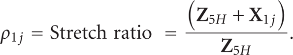
Here, the line of action of the slider is offset by a distance d1 (
In function generation problem, the input (φ12, φ13) and output motions (
using loop closure equation of vectors, for the initial position (Figure 2)

where in
and
For the jth position (Figure 2)

where

Writing (5) for 3 positions of the slider
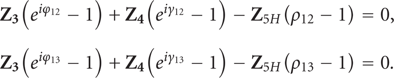
Rewriting (6) in the following form:
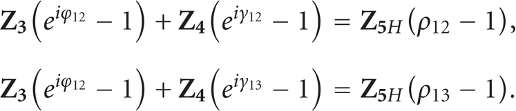
Writing in the matrix form,

Here,

Let

Then,


Also from loop closure equation

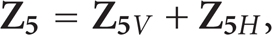
Thus,
The constant vector

From (1),

where α = angle made by the vector
When the mechanism moves from position 1 and reaches position 3, it stops and further motion is ceased. Here, in this position Phase II synthesis is considered. In Phase II, the link 2 is released for motion and the slider is temporarily fixed.
2.1.2. Phase II
In the present problem, more emphasis is given on finding out the link lengths rather than the number of positions. It is seen that while finding out the link lengths in Phase I, the three positions yielded two equations of motion. After prescribing and assuming some of the unknown parameters, two unknown vectors are left with. Two equations of motion are sufficient to solve the problem, that is, to find out the two unknowns in Phase I.
Because we make use of the same link lengths found in Phase I for the configuration of mechanism in Phase II, we have very few unknowns to find out. Therefore, it is felt that two positions yielding one equation are sufficient to find out the only remaining unknown. However, there is nothing wrong in going for three or four positions of synthesis. There will be a change in the number of solutions depending upon the number of free choices made. It will be ∞3 solutionsfor two positions of synthesis, ∞2 solutions for three positions of synthesis, ∞1 solutions for four positions synthesis and so-on, in Phase II [3, 4, 29].
Here the input angle is θ34 and the output link PB describes γ34. It is required to coordinate the angular motion between the input link 2 and the output link 4 for the function generation. Hence, the prescribed parameters are γ34 and θ34. Assuming the coupler angle φ34 for the link 3, the only unknown
Writing dyadic equation (Figure 3)

Herethe only unknown is

By loop closure equation and referring to Figure 1,

Therefore,

Also, from loop closure equation andreferring Figure 3,

Hence all the design parameters of the five-bar-slider mechanism with variable topology are determined from Phase I and Phase II.
2.1.3. Centric Slider-Crank Mechanism
From (2)

Then,

Hence, a special case is in (Figure 5). The mechanism becomes an inline or centric slider crank mechanism of one degree of freedom when offset equals to zero. Hence, the line of action of the slider is passing through the temporarily fixed pivot A (Figure 5). The synthesis procedure is similar to Phase I of an offset five-bar slider mechanism. All equations from (3) to (12) are applicable except that
The procedure of synthesis of Phase II (Figure 6), is also similar to Phase II of an offset five-bar mechanism with variable topology. The unknown vectors
3. Application
The off-set five bar slider mechanism with variable topology may be used as the double locking device for gate, cupboards, refrigerators, and so forth. The double locking device increases the degree of safety. The operations of Phase I and Phase II are shown in Figures 7(a), 7(b), 7(c), 8(a), 8(b), and 8(c)foran offset five-bar slider mechanism with variable topology and a centric five-bar slider mechanism with variable topology, respectively.

(a) An offset double locking device. (b) Operation of an offset double locking device, Phase I. (c) Operation of an offset double locking device, Phase II.

(a) Centric double locking device. (b) Operation of centric double locking device, Phase I. (c) Operation ofcentric double locking device, Phase II.
4. Examples
Example 1 (1). It is required to synthesize an offset five-bar slider with variable topology mechanism as shown in Figure 7 for double locking device of a gate. Given that φ12 = 30.20° CW, φ13=56.57° CW,
Solution.
Phase I. Assuming γ12 = +4.45 ° and γ13 = +13.07°;
From (11),
From (12),
From (13),
From (14),
From (15),
Phase II. Assuming φ34=+38.40°;
From (18),
From (19),
Also from (20),
Example 2. It is required to synthesize a centric five-bar slider with variable topology mechanism as shown in Figure 8 for double locking device of a gate. Given that φ12=23.27° CW, φ13=45.15° CW,
Solution.
Phase I. Assuming γ12 = +6.28 °, γ13 = +18.22°;
From (11),
From (12),
From (13),
Phase II. Assuming φ34=+49.00°;
5. Conclusion
The present work suggests variable topology method using dyad techniques for synthesizing an offset five-bar slider mechanism for three positions in Phase I and two positions in Phase II. It is synthesized for the task of function generation. Complex numbers, which readily lend themselves as an ideal tool for modeling linkage members as parts of planar mechanisms, are used for writing displacement equations for dyads. The method used here is a noniterative and has an increased accuracy over the graphical methods and also the advantage of transforming the two degrees of freedom of a five-bar slider mechanism to single degree of freedom mechanisms, separately. Applications of an off-set five-bar slider mechanism with variable topology and a centric five-bar slider mechanism with variable topology are also illustrated.