
Abstract
The present study focus on evolution of compressible vortex ring generated at the open end of a shock tube through accurate measurement of velocity field using Particle Image Velocimetry (PIV). To investigate the unsteady characteristics of embedded shock-free, low Mach number vortex rings, two cases (shock Mach numbers, M=1.27 and M=1.37) are considered for PIV measurements. Time-dependent variations of circulation, core and ring diameters, and ring velocity are calculated from the measured velocity field. Pinching-off process is investigated in detail for both cases. Formation time and the time of complete detachment of the vortex ring from the trailing jet are identified from the velocity and vorticity field. The ring formation is complete at about t
*
(=tU
b
/D)=1.75 and 1.65 for M=1.27 and 1.37, respectively, where t is time, U
b
is fluid velocity behind the shock at exit, and D is tube diameter. Complete detachment of the vortex ring from the trailing jet is observed at
1. Introduction
A vortex ring is a bounded region of vorticity in a fluid in which vortex lines form closed loop. A large volume of research has been published on incompressible vortex rings; for extensive reviews, see Shariff and Leonard [1] and Lim and Nickels [2] and the mathematical details are given in Saffman [3], Lamb [4], and Batchelor [5] and experiments [6, 7]. In recent years, there have been several studies in the area of compressible vortex rings [8–10]. These studies deal with various phenomena such as, sound generation associated with the formation of vortex rings, vortex-vortex interactions, and shock-vortex interaction.
Compressible vortex ring generated from the open end of a shock tube at high incident shock Mach number (M) is an important study due to the presence of shock/expansion waves in the flow field and large variations in thermodynamic and physical properties across the vortex ring. Though the generation mechanism is simple, the unsteady nature of the flow field facilitates understanding of many transient, compressible flow events and associated noise generation mechanism. Shock generated compressible vortex ring at the open end of a duct simulates cold flow from a pulsed detonation engine, where a train of propagating waves are used to generate high transient thrust. It also simulates starting flow field from a rocket nozzle, diesel engine exhaust mufflers, and pulse combustors. Compressible vortex ring emerging from the open end of a shock tube is first studied experimentally by Elder and De Hass [11]. Trajectories of the vortex ring and the incident shock are measured using spark Schlieren photographs for shock Mach number M=1.12 and 1.32. Moore [12] derived a theoretical expression for the propagation velocity of compressible vortex ring. Arakeri et al. [13] studied the flow field of a vortex ring at an open end of a short driver section shock tube using particle image velocimetry (PIV). They examined the early evolution of the vortex ring for three different Mse = 1.1, 1.2 and 1.3 and found that the vortex ring formation is complete at nondimensional time t * =tUbe/D=2 where, Ube is the velocity behind the incident shock at shock tube exit which is measured from PIV experiments, Mse is the shock Mach number at the exit calculated from Ube and D is the diameter of shock tube. They also observed that the translational velocity of the ring after formation is 0.7U b .
Baird [14] studied the flow phenomenon of supersonic vortex ring formed at the open end of the shock tube using differential interferometry. The flow visualization pictures reveal that an embedded rearward facing shock lies in the recirculation zone of the vortex ring at shock Mach number M=1.5. He confirmed the presence of the embedded shock by on-axis pressure measurements and simplified quasisteady calculations. Brouillette and Herbert [15] using Spark Shadowgraph and Schlieren techniques identified the existence of an embedded shock wave inside the ring for shock Mach numbers greater than 1.43, and shock-free vortex rings below this Mach number for critical driver section length. Murugan and Das [16] studied the characteristics of high Mach number compressible vortex ring generated at the open end of the shock tube using high-speed laser sheet-based flow visualization. The formation mechanism and the evolution of counter rotating vortex ring formed ahead of the primary vortex ring are studied in detail for shock Mach number M=1.7 with different driver section lengths.
Apart from the ring characteristics, the other important aspect of the vortex ring is its formation time. The formation number or initiation of pinch-off is defined as the non-dimensional time at which the vortex ring can attain maximum circulation during its formation [17]. Once the vortex ring reaches this non-dimensional time, no more circulation is fed into the ring. The pinch-off process is not a sudden process. A two stage process can be observed before complete detachment of vortex ring from the trailing jet [18]. Mohseni [19] has theoretically analyzed the vortex ring formation and pinch-off at the exit of a shock tube. The detailed mechanism of pinch-off process can be found in [20, 21].
There are only few experimental studies available in the literature on compressible vortex ring and its properties such as propagation velocity, formation times, and velocity and vorticity distributions within the core. Present study is an effort to fill this gap by extensive experiments. All the earlier studies mentioned above lack the quantitative information except Arakeri et al. [13]. The present study investigates the characteristics of shock free vortex ring along with the pinching-off process through quantitative measurements. Brouillette and Hebert [15] from their Shadowgraph visualization study reported that for shock Mach number M┼1.43, the vortex ring is free of embedded shock and the embedded shock forms for M>1.43. The present study comes under shock free region (M┼1.43). The measured data in the present study is of higher accuracy in comparison to the earlier study of Arakeri et al. [13] and the details of the core at later times of the vortex ring have been reported. Experiments are performed with a longer driver section length compared to earlier study of Arakeri et al. [13] to know the nature of pinching-off process.
2. Experimental Setup
The schematic of the experimental setup is shown in Figure 1. An open ended shock tube of driver section length 285 mm is used to generate compressible vortex rings. The inner and outer diameter of the tube is 64 mm and 100 mm, respectively. Two different driver section pressures of 2.06 and 3.1 bar are used to study the flow field. The driven section of the shock tube is 1200 mm long. Helium is used as a driver section gas. A straight nozzle with sharp exit angle of 60° is attached with the driven section to have the smooth rolling up of vortex sheet at exit. Aluminum and Mylar sheets of different thicknesses are used as diaphragms. Diaphragm is ruptured using a pneumatic plunger.
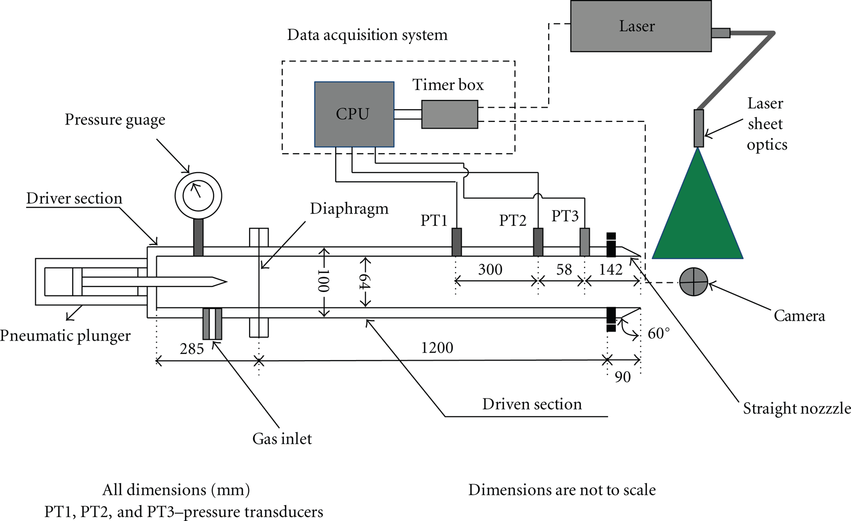
Schematic represented of the experimental setup.
Particle image velocimetry (PIV) technique has been employed for measuring the velocity field of the flow emerging from the shock tube. A double-pulsed Nd: YAG laser (200 mJ/pulse, 10 Hz) is used for illuminating the flow field. The beam is delivered from laser head to the experimental zone by an articulated arm with a sheet forming optics at the end. The sheet forming optics consists of two spherical lenses and a cylindrical lens. The thickness of the sheet is approximately 1mm. The sheet is aligned to the centre line of the shock tube and cuts the radial plane. A 12-bit CCD camera of 4 MP (megapixel) resolution is used for capturing the particle images. The frame rate of the camera is 4 Hz in double frame mode.
The pressure data is acquired at a sampling rate of 100 kSa/s using NI 4472, 24-bit sound and vibration DAQ (Data Acquisition) card. Voltage signal from a pressure transducer (PT) mounted on the shock tube wall is used for triggering the delay unit. The delay unit is an external delay generator which has a variable delay from 1 μs to 10 ms. This delayed signal is used to trigger the PIV acquisition system. Flow field at different times is captured by adjusting the delay in the delay generator.
The PIV acquisition system comprises of a synchronizer (NI PCI-6602 timer box), which synchronizes the laser and camera. The laser is having a delay of 200 μs. The laser and camera is synchronized by delaying the camera to 200 μs. PIV measurements are carried out in dark conditions. The time between the two laser pulses is optimized from parametric study and 3 to 5 μs have been used for these high-speed measurements. Fog is used as seeding in all the experiments. The driven section is filled with fog prior to the bursting of the diaphragm. The diameter and density of the seeding particles are 1 μm and 1.353 kg/m3, respectively. In order to estimate how strictly the seed particles follow the fluid and their response to high velocity gradients, particle Stokes's number has been calculated. Stokes's number (Stk) is the ratio of the particle relaxation time (τ p ) to the characteristic time scale of the fluid (τ f ). The particle relaxation time is given by Melling [22]

where ρ p is the particle density, d p it is diameter of the particle, and μ is the fluid viscosity. The fluid time scale is given by
where L f is characteristic length and U f is the characteristic velocity. The inner diameter of the shock tube (D) is taken as L f and maximum induced velocity behind the shock wave as U f . The Stokes's number is calculated as Stk=1.16×10− 5. As Stk is far less than 1 the seeding particles can respond to the high velocity gradients of the flow.
Dynamic Studio software of Dantec Dynamics is used for acquisition and analysis of the captured particle images. The total area of the captured images is 150 mm × 150 mm. Analysis is carried out with interrogation window of size 32×32 pixels and an adaptive correlation with a 50% overlap.
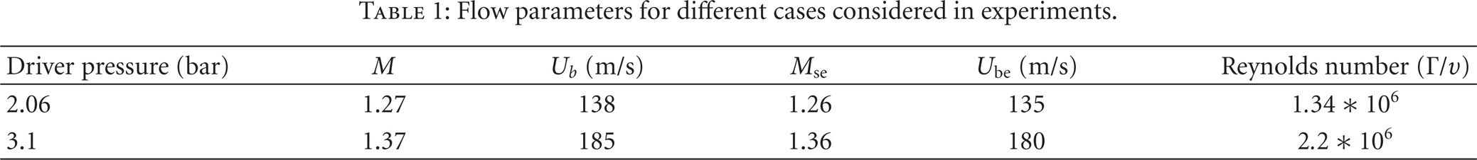
Table 1 shows the different flow parameters considered for the experiments. M is the shock Mach number measured from the pressure transducer (PT) signals. U b is the velocity behind the shock calculated from normal shock relations based on the measured shock Mach number (M). Ube is the velocity behind the shock from the PIV measurements when the shock is exactly at the exit. Mse is the calculated Mach number based on Ube. Obtaining Ube from the PIV measurements for every case is cumbersome process. Also Ube can only be measured when the shock is at least 2 mm ahead of the tube. To overcome this problem, three pressure transducers (PT) are mounted on the shock tube towards the exit. PT2 and PT3 are placed much closer to the exit (see Figure 1). The distance between PT1 and PT2 and PT2 and PT3 is 300 mm and 58 mm, respectively. The difference in two values in shock speed calculated from PT1 and PT2 and PT2 and PT3 is less than 0.4%.
Flow parameters for different cases considered in experiments.
For a given driver pressure, we performed 30 experiments to check the variation of the shock speed. The variation in the shock speed is found to be less than 1%. For a given driver pressure, the same delay and the same time between the pulses, the repeatability of the experiments are conducted for 4 runs and the maximum variations in the ring position is 0.5%. The uncertainty analysis has been performed and the ring diameter is measured with an accuracy of ±0.5 mm. The uncertainty in the translational velocity of the vortex ring is ±1.05 m/sec.
PIV calibration is conducted by insertion of a calibration plate at the same position as the laser sheet. The orientation of laser sheet with calibration plate, distortion by lens and CCD, data processing and particle lag are considered for calculating the error in displacement and velocity. The error in displacement is ±0.016 mm and combined uncertainty in the velocity measurement is ±3.0 m/s.
3. Results and Discussion
Velocity and vorticity field of compressible vortex ring are obtained for two Mach numbers M=1.27 and M=1.37 using PIV. As only one particle image pair is obtained from each experiment, the data points showed in the plots below are from different experiments. The maximum percentage variation in M is ±1% for both cases. The ring characteristics such as circulation, core and ring diameter, and translational velocity are calculated from the measured velocity field. The x-axis is oriented along axial direction of the vortex ring while y-axis is oriented perpendicular to x-axis. In cylindrical coordinate system, y-axis corresponds to radial direction.
3.1. Flow Field of Propagating Vortex Ring
The shock diffracts at the open end of the shock tube and expands in the quiescent ambient, imparting a flow behind it and moves away. This causes reduction in pressure at the exit and is communicated by sending expansion waves into the tube. Expansion waves move upstream as the flow behind the primary shock is subsonic, and accelerates the flow inside the shock tube. The accelerated fluid exits the tube and the separated shear layer rolls up into a vortex ring [23]. A trailing jet is formed behind the vortex ring. The length and duration of the trailing jet depends on the driver and driven section lengths and shock Mach number [24, 25].
Figure 2 shows the instantaneous PIV images and their corresponding velocity fields for M=1.37 after the diffraction of incident shock at the open end of the shock tube. Time at which the incident shock reaches the exit is taken as t=0. In Figure 2, the left column shows the particle images, the middle column shows corresponding velocity vector maps and the third column shows the azimuthal-component of vorticity. Figure 2(a) (images of first row) to Figure 2(d) (images of fourth row) show the development of the vortex ring during initial period covering a region from x=0 (exit of the shock tube) to x=150 mm. The images in Figure 2(e) cover x=60 mm to x=210 mm, and Figure 2(f) cover x=120 mm to x=270 mm. The shock tube is shifted back from measurement region to capture the vortex ring at later times.

Instantaneous PIV images (left column) and their corresponding velocity (middle column) and vorticity contours (right column) for M=1.37 at different times t = (a) 215 μs (t * = 0.62), (b) 434 μs (t * = 1.25), (c) 647 μs (t * = 1.87), (d) 990 μs (t * =2.86), (e) 1396 μs (t * = 4.03), (f) 2090 μs (t * = 6.05).
Development of flow field for M=1.37 is described in conjunction with Figures 2 and 3. Figure 3 shows the axial velocity distribution along the vortex plane Y v (see Figure 2(b)) and planes downstream (Y v +D c ) and upstream (Y v − D c ) of the vortex plane, where D c is the core diameter. Figure 2(a) shows the flow field at t=215 μs. At this time, the vortex ring is attached to the lip of the nozzle, and the incident shock can be clearly identified from the velocity field. The vortex ring forms completely and detaches from the shock tube at t=434 μs. The ring after formation accelerates in both axial and radial directions due to expansion of flow at exit [13]. At this stage, the trailing jet expands continuously as observed in Figures 3(a), 3(b), and 4. The velocity behind the vortex plane is summation of the velocity induced by the vortex ring and the velocity of the expanding fluid. The ring grows continuously after formation which can be seen from Figure 2(a) to Figure 2(c).
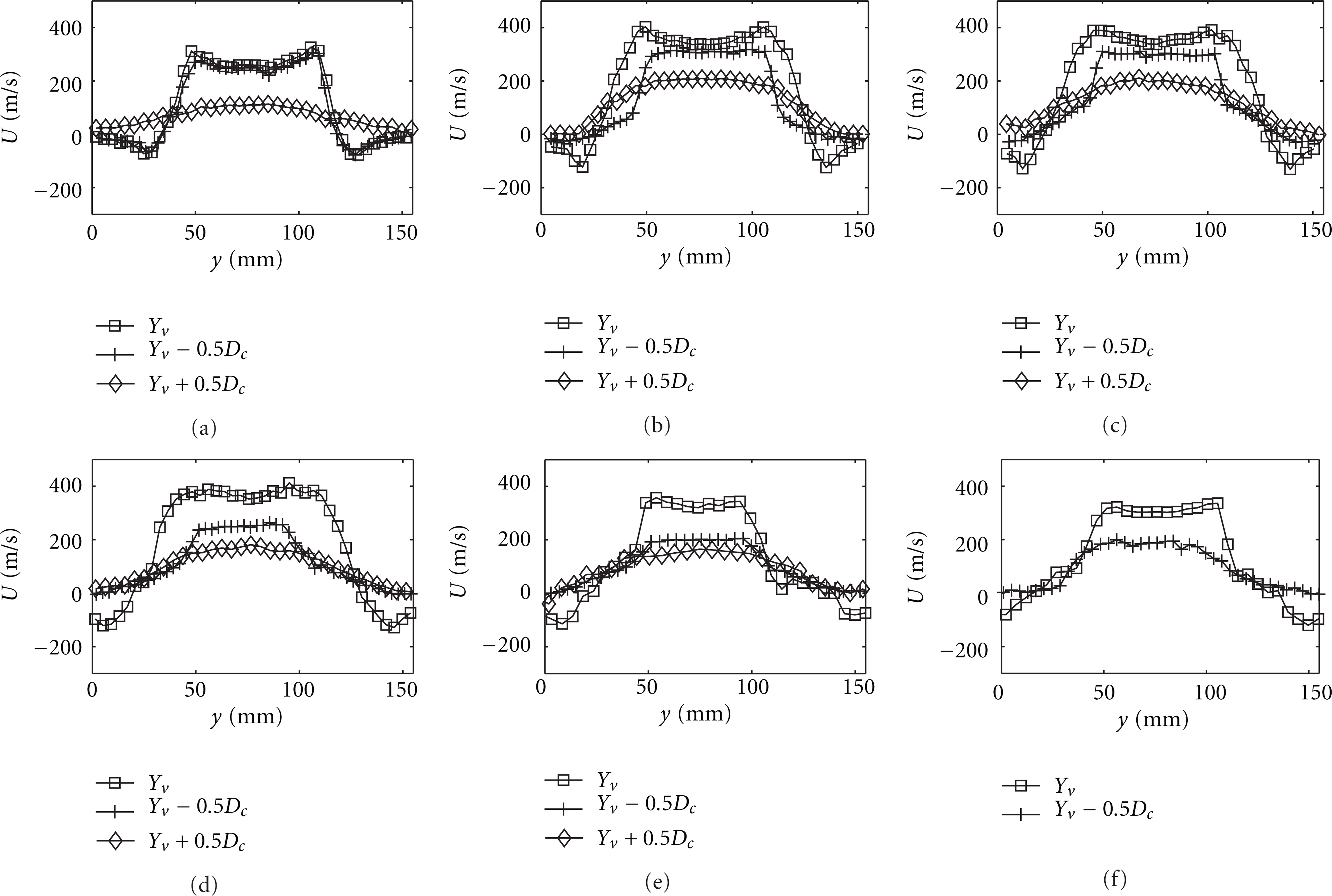
Axial velocity profiles for M=1.37 at different times (a) 215 μs, (b) 434 μs, (c) 647 μs, (d) 990 μs,(e) 1396 μs, and (f) 2090 μs.

Variation of nondimensional exit velocity with non-dimensional time.
Figure 2(c) (t=647 μs) shows the vortex ring, the jet following the ring and shear layer vortices. The vortex ring increases its strength, as it is fed continuously by the shear layer vortices. This increases the self induced velocity of vortex ring. Thus, the velocity in the vortex plane in Figure 3(c) is more than the velocity behind it. In subsequent times, velocity behind the ring (Figures 3(c) to 3(f)) is less compared to that in vortex plane.
During the development of flow, the core of the vortex ring becomes transitional (Figures 2(a) and 2(b)). Although the jet and the shear layer are smooth with little undulation (Figures 2(a) and 2(b)), the core region becomes transitional and wavy in nature. The core disturbances grow gradually and make the ring turbulent. The turbulent nature of the flow can be observed in cross sectional velocity profiles, where small scale fluctuations are observed (Figures 3(e) and 3(f)). Flow visualization pictures for t greater than 647 μs (Figures 2(d)–2(f)) shows such turbulent character of the flow field. Large shear layer vortices can be observed in these pictures. The velocity field shows nearly uniform jet flow behind the vortex ring for t less than 647 μs. The jet velocity is affected severely due to the presence of vortex ring in subsequent times. The vortex ring acts like a convergent divergent nozzle with throat along the vortex plane. The sequence of images from Figure 2(d) to Figure 2(e) shows the initiation of pinching-off process. During the pinch-off process, the ring separates from the jet and moves with self induced velocity, the shear layer vortices stops entering the primary ring. The details of pinching-off process and formation times are discussed in Section 3.3.
The shock induced vortex rings are different from the incompressible vortex rings in terms of the exit velocity variation with time. In case of piston-generated rings, the exit velocity is equal to piston velocity over a course of time, whereas in the present case the exit velocity accelerates to 1.8U b and then decelerates (see Figure 4). This is due to expansion of flow at the exit. Variations of the non-dimensional exit velocity with non-dimensional time (Figure 4) are almost same for both cases considered and hence, the flow field during early stage of development is similar. The difference appears only in the strength of the trailing jet and that of the vortex ring. These differences causes variation in the pinching-off process of the two cases and discussed in Section 3.3. Note that the variations of the exit velocity is similar that of Arakeri et al. [13].
3.2. Centerline Velocity Variation with Time
Figure 5 shows the centerline axial velocity profiles at different times for M=1.37. Change in the velocity is gradual in the axial region with maxima at the vortex plane after initial time t greater than 215 μs. Although the centerline velocity in the vortex plane becomes marginally supersonic at t=434 μs no embedded shock has been observed in the axial region of the vortex ring. This is due to the fact that the velocities are subsonic in vortex frame of reference. The vortex ring translation velocity with respect to time can be obtained by locating the position of peak velocity at different times for t greater than 215 μs (see Figure 5).

Centerline velocity variation of vortex ring for M=1.37 at different times.
The expansion of flow at the shock tube exit is restricted by the formation and growth of the vortex ring as shown in Figures 2(a)–2(f). The effective area of flow is reduced by a small amount at the vortex plane during the evolution of vortex ring. Hence the subsonic flow at the exit is accelerated towards the vortex plane due to reduction in effective area. However, the flow is decelerated ahead of the vortex plane due to increase in effective area. Hence, the vortex plane acts as a minimum area in the flow field.
3.3. Characteristics of the Ring
Ring diameter D r and core diameter D c are the two important geometric parameters that describe a vortex ring. The other important quantities that describe the flow of vortex ring are ring velocity, ring circulation, and velocity and vorticity distributions in the core of the ring. All these quantities are quantified and analyzed in this section.
3.3.1. Ring Diameter
The ring diameter is defined as the distance between center of the bottom and top cores of the ring in the radial cross-sectional view. Figure 6(a) shows a typical curve for the evolution of vortex ring diameter and appropriate non dimensional parameters are used to plot the data. Ring diameter is found to increase initially (during formation) and finally attains an asymptotic value at about t * = 2.8. The asymptotic value of ring diameter is about 1.58D, for both cases. The ring diameter of M=1.37 is found to increase after reaching the constant value. The ring diameters are compared with earlier study of Arakeri et al. [13]. It is observed that for all the cases non-dimensional data collapses before the initiation of pinching-off process. The behavior afterwards can be attributed to the differences in the flow field at later time for different M and discussed in Section 3.3.

(a) Variation of the ring diameter with time. (b) Variation of the nondimensional ring diameter with non-dimensional time.
3.3.2. Core Characteristics
The core of the vortex ring is the region of recirculation zone, where the flow is rotational. As the vorticity decays gradually from the core center, usually the core of the vortex ring is identified from the distribution of velocity [6, 13]. Peak positive to peak negative velocity represents the core without much ambiguity. Figure 7(a) shows an instantaneous transverse velocity profile in the core. The core diameter is defined as the distance between the two peaks in the velocity profile shown in Figure 7(a). Corresponding vorticity distribution is also seen in the same Figure. It is observed from Figure 7(a) that at the point of peak velocity the value of vorticity has dropped nearly 98% of maximum vorticity. The velocity profile shows a linear variation within the vortex core and is followed by inverse variation with the distance from the core. Although the compressible vortices are characterized by steep density and temperature profiles within the core, interestingly, their velocity distribution within the core is similar to that of an incompressible vortex [10]. At initial stages of ring formation, velocity within the core is measured properly, whereas at later stages the particles are thrown away from the center due to centrifugal action and makes the measurements difficult. To resolve the core, different concentration of smoke was used in the current study. Figure 7(b) shows a typical curve for the evolution of vortex ring's core diameter with nondimensional time. Unlike D r /D, the D c /D variations with t * are unalike for different M. Even though the non-dimensional ring diameters are same before the initiation of pinching-off process, the shock Mach number greatly influences the size of the core.

(a) Transverse velocity and vorticity profile within the vortex core at t=390 μs and M=1.37. (b) Variation of the nondimensional core diameter with nondimensional time.
3.3.3. Translational Velocity of the Ring
The vortex ring propagates freely in ambient space due to its self induced velocity. In the present experiment, the translational velocity is measured by taking double-exposed pictures with large time (50 μs) between the two exposures. The time between the two exposures is chosen such that the core displacement is sufficient. Figures 8(a) and 8(b) shows the dimensional and non-dimensional variation of translational velocity with time for the two Mach number cases considered. The translational velocity of the ring increases during the formation process and reaches an asymptotic value 0.8U b at t * = 1.75. During the formation process the ring translates in axial, as well as in radial direction. However, the ring after formation translates predominantly in the axial direction with nearly constant speed (see Figure 8(b)). The translational velocity of the compressible vortex ring is calculated theoretically from Moore [12] using measured values from PIV. It has been observed that theoretical values are in agreement with the experimental values.
(a) Variation of translational velocity of the ring with time. (b) Variation of nondimensional translational velocity of the ring with nondimensional time.
3.3.4. Variation of Circulation with Time and Pinching-Off Process
Figures 9(a) and 9(b) show the variation of circulation of the vortex ring with time for both cases in terms of dimensional and non-dimensional quantities, respectively. The circulation has been calculated by taking a closed circuit enclosing the ring in the azimuthal plane. The method followed is same as that of Arakeri et al. [13] and hence not discussed in detail here. The average of two values (top and bottom half of the picture) is taken as circulation. The circulation values are compared with earlier study of Arakeri et al. [13]. Circulation increases rapidly during the initial roll up and growth of the vortex ring due to continuous feeding of vorticity into the core by the shear layer. However, after formation the circulation is almost constant during the evolution of vortex ring. The velocity vector plot (Figure 2) shows no discontinuity and appears to be a vortex ring attached with the trailing jet. However, the vorticity contour in Figure 2(c) indicates a discontinuity in the vorticity field between the shear layer and vortex ring, when compared with that of Figures 2(a) and 2(b). The same has been observed for M=1.27 case (see Figure 10). In Figure 10(a), the shear layer is connected with the ring where as Figure 10(b) shows the initiation of pinching-off.
(a) Variation of circulation of the vortex ring with time. (b) Variation of the nondimensional circulation with nondimensional time.

Instantaneous PIV images (left column) and their corresponding velocity (middle column) and vorticity (right column) contours for M=1.27 at different times (a) 740 μs (t * = 1.59), (b) 973 μs(t * = 2.09), (c) 1689 μs (t * = 3.64).
Figure 11 shows the total circulation and ring circulation. The total circulation is the total amount of circulation ejected from the tube, which includes the jet as well as ring circulation. The total circulation continuously increases with time until the exit velocity becomes zero. The formation number or initiation of pinch-off is defined as the non-dimensional time at which the total circulation is equal to the maximum circulation of the vortex ring [17]. The formation time for the two cases (M=1.27 and M=1.37) is observed as t * ≈1.75 and 1.65, respectively. Beyond this time, vorticity is fed into the primary ring by the discrete shear layer vortices as seen in Figures 2(d) and 2(e). The jet velocity upstream (at 2 D c distance from vortex plane) is plotted in Figures 12(a) and 12(b) for M=1.27 and 1.37, respectively. At t=990 μs (t * = 2.86) the jet velocity is 240m/s (Figure 12(b)) and the ring velocity is 150m/s (Figure 8(a)). Thus, the discrete shear layer vortices are dragged into the primary vortex ring by the jet. This is the mechanism through which the ring's circulation increases beyond the formation time. When the jet velocity decrease substantially, the feeding of vorticity stops, and the ring circulation attains a constant value (see Figure 9(b) at t * = 2.9). We call this time as detachment time similar to that of Gao and Yu [18]. Although Gao and Yu [18]in their theoretical model predict the difference between formation time and time of detachment is greater than 3, it is not observed in the present cases. For M=1.37, the time difference is about 1.2 and that for M=1.27 is 0.25 (see Figures 11(a) and (b)). The differences in these values can be attributed to the nature of the jet. The jet is sufficiently strong after formation for M=1.37 case (Figure 12(b)) and able to drag some of the detached shear layer vortices into the primary ring. For M=1.27 case the jet (Figure 12(a)) is not strong enough for the same. During pinch-off, the jet velocity decreases and considerable growth of shear layer vortices is observed (see Figures 2(e) and 2(f)). The pinch-off times (complete detachment of leading vortex ring from jet) are observed as t * ≈2 and 2.9 for M=1.27 and 1.37, respectively.

Variation of total circulation and circulation of the vortex ring for (a) M=1.27 and (b) M=1.37.

Axial velocity profiles of the jet at 2D c upstream of vortex plane (a) M=1.27 (b) M=1.37.
Noticeable differences have been observed between the two cases, during the detachment process of the vortex ring. The detachment process for M=1.37 case is shown in Figures 2(e) and 2(f) and that for M=1.27 is shown in Figures 10(b) and 10(c). For both cases during detachment the trailing, jet shear layer forms another vortex ring of same circulation behind the primary ring. This aft vortex ring is symmetric and oblique with the axis of the primary vortex ring for M=1.37 and 1.27, respectively. The symmetric aft ring induces a radial outward velocity on the core center of the primary ring for M=1.37 case in a fashion similar to that of leapfrogging rings. This is why an increase in primary ring diameter has been observed for M=1.37 case in Figure 6(b).
4. Conclusions
In this paper, evolution of compressible vortex ring, formed at the open end of the shock tube, is studied for shock Mach numbers M=1.27 and 1.37 through detail measurement of flow field using PIV. The geometric characteristics of the ring are measured in terms of variations of core diameter and ring diameter. Kinematic and dynamic characteristics are discussed through measurement of translational velocity of the ring, velocity, and vorticity distributions within the core. Variations of circulation with time are calculated from the measured velocity field which has depicted the pinching-off process in details. The following are the conclusions from the present study.
The shock induced vortex rings presented here are different from the incompressible vortex rings in terms of the exit velocity variation with time other than the compressibility effect. It has been observed that the exit velocity initially increases to 1.8U b before decay.
Ring diameter is found to increase initially and finally attains an asymptotic value at about t * = 2.8. The asymptotic value of ring diameter is about 1.58D for both cases.
The core diameter is found to attain a constant value after initial formation. The velocity and vorticity distributions within the core are similar to that of the incompressible vortex ring. Tangential velocity across the core of the vortex ring varies linearly and vorticity distribution is nearly Gaussian.
During the formation process, the ring translates in axial as well as in radial direction. However, the ring after formation translates predominantly in the axial direction with nearly constant speed. It has been observed that theoretical values of translational velocity are in agreement with the experimental values.
Circulation is found to increase rapidly during the initial roll up and growth of the vortex ring due to continuous feeding of vorticity into the core by the shear layer. However, after formation the circulation is almost constant during the evolution of vortex ring.
The details of formation and complete detachment of vortex ring from the trailing jet are studied for both the cases. Although the process of formation and complete detachment described by Gao and Yu [18] for incompressible vortex rings is observed in our experiments, the exact numbers are different from their theoretical values. The ring formation is complete at about t * = 1.75 and t * = 1.65 for M=1.27 and 1.37, respectively. The detachment times (complete detachment of vortex ring from jet) are observed as t * =2 and t * = 2.9 for M=1.27 and 1.37, respectively.
Footnotes
Nomenclature
Acknowledgments
The authors would like to acknowledge Department of science and technology (DST, India) and Indian Space Research Organization (ISRO) for partial financial support.