
Abstract
The present paper proposes a novel cableless magnetic actuator with a new propulsion module that exhibits a very high thrusting force. This actuator contains an electrical inverter that directly transforms DC from button batteries into AC. The electrical DC-AC inverter incorporates a mass-spring system, a reed switch, and a curved permanent magnet that switches under an electromagnetic force. The actuator is moved by the inertial force of the mass-spring system due to mechanical resonance energy. The experimental results show that the actuator is able to move upward at a speed of 19.7 mm/s when using 10 button batteries when pulling a 20 g load mass. This cableless magnetic actuator has several possible applications, including narrow pipe inspection and maintenance.
1. Introduction
There is increasing demand for in-piping robots able to quickly find damage and remedy undesirable conditions inside pipes used in plants for chemical and biological materials, nuclear power, and other such installations. Safety issues have encouraged the growing use of such robots in recent years for a variety of duties, including not only inspections, but also maintenance and cleaning. A number of studies have investigated the mechanisms of an actuator having an attached electric cable to provide locomotion in the pipe using devices such as piezoelectric elements [1, 2], shape memory alloys [3, 4], and electromagnetic motors [5–9]. However, little research has been conducted on cableless robots [10–12]. In general, the design of cable type robots is quite simple compared to the design of cableless robots. There are several potential problems in the design, however, with regard to extending the range and avoiding tangling of the cable, and thus it is clearly desirable to adopt a cableless system. Although long-range movement is necessary for the inspection of thin pipes in plants, no cableless mover capable of movement over one hundred meter in a thin pipe of several millimeters has been developed.
The present authors previously proposed [12] a novel cableless magnetic actuator that provides propulsion by means of the inertial force of a mass-spring system excited by an electromagnetic force. Since a large-amplitude vibration can be easily provided by a small excitation force, this type of the actuator has high propulsion.
This paper proposes a new type of the cableless magnetic actuator which exhibits a very high thrusting force and is capable of extension to propulsion of the robot within a thin pipe. In order to improve the moving characteristics of the actuator, an increase in magnetic force by the application of a new propulsion module was achieved. In addition, this cableless magnetic actuator contains an electrical inverter that directly transforms DC supplied from button batteries into AC. The electrical DC-AC inverter is composed of a reed switch and a curved permanent magnet that switches under an electromagnetic force. The propulsion of this cableless magnetic actuator exhibits good performance compared with other types of actuators that are powered by an electric cable [1–9]. Additionally, experiment results were compared to simple analytical results, and the validity of the motion principle by means of inertial force was completely verified.
Finally, we considered a reversible motion of the actuator using the magnetic field of permanent magnets arranged outside the pipe.
2. Cableless Magnetic Actuator
Figure 1 is a diagram of the cableless magnetic actuator capable of moving within a pipe having an inner diameter of 8 mm. The magnetic actuator consists of two identical ring-type permanent magnets, two translational springs, a bobbin-type electromagnet, a frame, ten button batteries, two rubbers, and an electrical DC-AC inverter composed of a reed switch and a curved permanent magnet. The ring-type permanent magnet is an NdFeB magnet that is magnetized in the axial direction. The magnet has an outer diameter of 7.8 mm, an inner diameter of 5.8 mm, and a thickness of 4.5 mm. The surface magnetic flux density measured using a tesla meter is 225 mT. The two identical translational springs are stainless steel compression coil type springs and have an outer diameter of 6 mm, a free length of 5 mm, and a spring constant of k=502 N/m. The bobbin-type electromagnet is composed of an iron core with 3200 turns of 0.06 mm diameter copper wire. The electrical resistance of the electromagnet is 224 Ω. This electromagnet also achieves duty of the mass of a mass-spring system by combining the two translational springs.
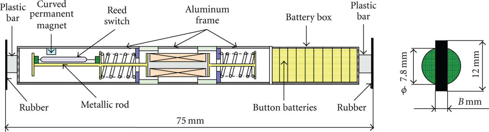
Structure of the cableless magnetic actuator.
As shown in Figure 2, the spring is glued to a plastic plate, and the electromagnet and the two springs are connected by two metallic rods with circular plates at both ends. The ring-type permanent magnets were then combined with a frame. The rubbers used to support the actuator are constructed from natural rubber and have a length of 12 mm, a width of B mm, and a thickness of 0.5 mm. The rubber was attached to the frame by a square plastic bar having a length of 6 mm as shown in Figure 1. The actuator, which houses ten button batteries, has a length of 75 mm and a total mass of 8.3 g.

Propulsion module of the actuator.
3. Increase in Magnetic Force by Improvement of the Propulsion Module
Figure 3 shows a sectional view of the magnetic circuit composed of two identical ring-type permanent magnets, two ring-type plastic plates, the frame, and a bobbin-type electromagnet. The iron core of the bobbin-type electromagnet consists of two identical circular plates having diameters of D mm and thicknesses of H mm, and a straight rod of 2.5 mm in diameter. The iron core of the bobbin-type electromagnet was roughly designed by computer simulation and then optimized experimentally.

Schematic diagram of the magnetic circuit.
As mentioned earlier, the propulsion module of this magnetic actuator must generate a stronger exciting force. Before the cableless magnetic actuator was fabricated, the static characteristics of the propulsion module were examined. The iron core having an integral structure was machined using a lathe.
An experiment was conducted using the apparatus shown in Figure 4(a). A direct current of 0.05 A was applied to the electromagnet during measurement. The origin of the measurement was taken as center of the ring-type permanent magnet, and position x was measured as shown in Figure 4(b).

Experimental apparatus.
Figure 5(a) shows the relationship between the position x and the static force as measured by the force gage with respect to the iron core having diameters, D, of 4.4 mm, 4.8 mm, and 5 mm, for thickness, H, of the iron core of 1 mm. On the other hand, Figure 5(b) shows the relationship between the position x and the static force as measured by the force gage with respect to the iron core having thicknesses, H, of 0.5 mm, 1 mm, and 1.5 mm, for diameter, D, of the iron core of 5 mm. The maximum static force was 0.43 N for the case in which H=1.5 mm and D=5 mm. On the other hand, the maximum static force was 0.42 N for H=1 mm and D=5 mm. Since the difference in maximum static force was slight among the investigated cases, the iron core with a circular plate of H=1 mm and D=5 mm was used in the present study.

Relationship between position and static force.
4. Structure and Operating Principle of the Electrical DC-AC Inverter
Figure 6 shows an outline of the electrical DC-AC inverter proposed in the present paper in order to realize the cableless actuator. Considering durability, the mechanical DC-AC inverter demonstrated in the previous paper [12] was exchanged for an electric inverter. The electrical inverter is composed of a reed switch and a curved permanent magnet, as mentioned above. The reed switch is 1.8 mm in diameter and has a length of 10 mm. The curved permanent magnet is an arc-type NdFeB magnet of 1.2 mm in width and 2.5 mm in thickness and is magnetized in the axial direction. The reed switch was attached at the metallic rod by using the two urethane rubbers. The reed switch and the bobbin-type electromagnet are connected by a thin copper wire to a DC source, such as a battery, as shown in Figure 6(a). The reed switch attached to the electromagnet vibrates around the curved permanent magnet. The strength and weakness of the magnetic field between the curved permanent magnet and the reed switch attached on the mass by the vibration displacement of the mass-spring system are generated. The mass-spring system vibrates, and the two cantilever beams inserted in the reed switch make and break contact as the switch is cycled on and off. As a result, the DC voltage is converted into a square alternating waveform, and the magnetic force operates on the mass-spring system.

Principle of the electrical DC-AC inverter composed of a reed switch and a curved permanent magnet.
The DC source for the experiment was composed of ten SR621 W silver-oxide button batteries. When the electromagnet was connected to the battery pack as shown in Figure 6(a), the direct current into the electromagnet was 0.05 A. Figures 6(b) and 6(c) show in detail the arrangement of the reed switch and the curved permanent magnet. The origin of the measurement was taken as the center of the curved permanent magnet, and the x and z coordinates, which are shown in relation to the left-hand side of the reed switch, were measured as shown in this figure.
Figure 7 shows the on-off area of the reed switch around the curved permanent magnet. In this figure, the center point indicates the contact point of the two cantilever beams inserted into the reed switch. The solid line indicates the on-area of the reed switch, and the broken line indicates the off-area.
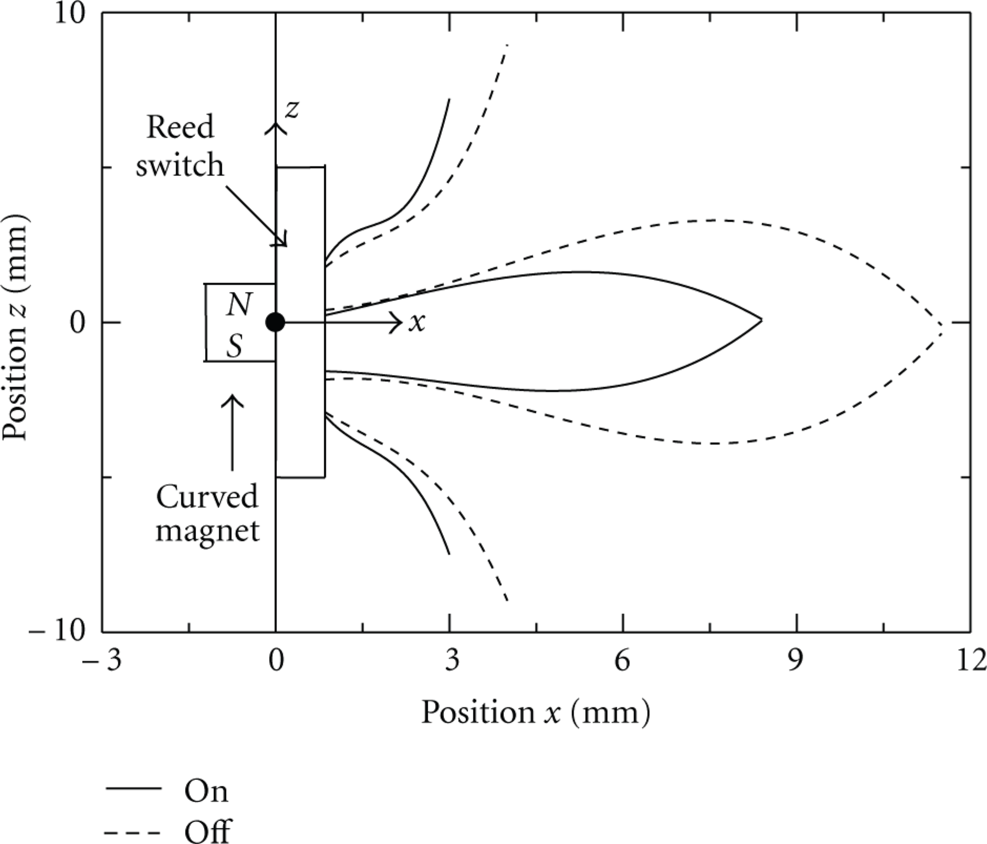
On-off area of the reed switch around the curved permanent magnet.
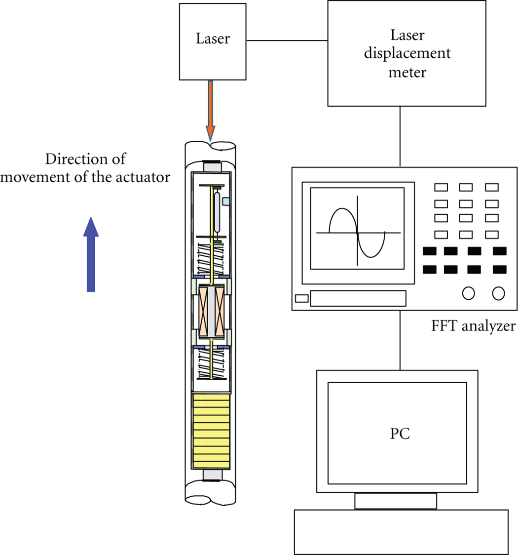
Figure 8 shows the experimental apparatus used to demonstrate a robustness of the mass-spring system. By using the impactor composed by an impulse bar and the spring as shown in this figure, the additional mass is removed from the mass-spring system. The current waveform generated during switching of the mass-spring system was stored in a PC via a fast Fourier transform (FFT) analyzer.

Experimental apparatus.
Figure 9 shows the time response of the mass-spring system and the current square wave when the resonance frequency of the vibrating mass-spring system was changed suddenly from 65 Hz to 100 Hz due to the removal of a 3.5-g mass from the mass-spring system. This mass-spring system vibrates stably after the sudden change in resonance frequency. The cableless magnetic actuator can be operated even if the resonance frequency of the mass-spring system changes due to environmental variation.

Time response of the mass-spring system and waveform of current.
5. Principle of Locomotion
The mass-spring system can be approximated as a two-degree-of-freedom model as shown in Figure 10(a) and Figure 10(b). In these figures, the mass of the two permanent magnets of ring-type, 10 button batteries, the curved permanent magnet, the two plastic plates of ring-type, the two plastic square rods, a frame, and the two rubbers is M, and the mass of the electromagnet, the two metallic rods with circular plates at both ends, and the reed switch is m, as shown in Figure 10(a). If the masses are treated as point masses and the displacements x i (i=1,2) are measured as shown in Figure 10(b), then the equations of translational motion can be written as follows:

Here, M=5.8 g and m=2.5 g, the first eigenfrequency is f1 = 100.8 Hz, and the second eigenfrequency is f2 = 120.7 Hz, respectively. Figure 10(c) illustrates the first mode. The first vibration mode occurs when the supporting force of the actuator increases. As the driving mode of the actuator, the first vibration mode capable of movement by comparatively high contact force was used.

Two-degree-of-freedom model.
We consider about one period τ of the vibration at the mass-spring system. The principle of locomotion is as follows.
For the region 0┼t┼τ/4, as shown in Figure 11(a), the rubbers can slide due to the inertial force of the vibrating mass when the mass of the mass-spring system vibrates in the x direction.
For the region τ/4┼t┼3τ/4, as shown in Figure 11(b), the tips of the rubbers are fastened to the wall inside the pipe when the vibrating mass moves in the negative x direction. The frictional force between the two rubbers and the inner wall of the pipe becomes rather large compared with the inertial force of the vibrating mass. Therefore, the actuator cannot be moved.
For the region 3τ/4┼t┼4τ/4, the vibrating mass maintains the harmonic vibration and returns to the origin. As a result, the actuator can only move in the x direction due to the inertial force of the vibrating mass of the mass-spring system. Thus, the actuator is propelled by the difference in the frictional force between the forward and backward motion of the two rubbers.

Principle of locomotion.
The kinetic energy E(= (1/2)M(A M ω)2) acting on the support part of the actuator and dissipation energy due to the frictional force between the two rubbers and the inner wall of the pipe are made to be equal. When the actuator moves straight upward, the speed of the actuator D i and the displacement δi per cycle of the vibration can be expressed as follows:
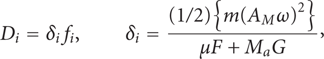
where μ is the coefficient of friction between the two rubbers and the inner wall of the pipe, M a is the total mass of the actuator, G is the acceleration of gravity, F is a supporting force of the actuator, A M is the vibration amplitude of the mass m, ω is the first angular frequency of the mass-spring system, and f i is the driving frequency of the actuator.
The vibration amplitude A M of the mass m at the moving actuator was measured experimentally, as shown in Figure 12. The vibration amplitude was provided by canceling the DC component using the FFT analyzer. The vibration amplitude A M was 0.625 mm when the supporting force of the actuator was 0.25 N and the coefficient of friction was 0.62. The speed measured in the experiment was 81.2 mm/s, and that calculated using (2) was 81.6 mm/s when the driving frequency f i of the actuator was 100 Hz.
Measurement of vibration amplitude for moving actuator.
The results are in good agreement. Accordingly, the validity of the motion principle by means of the inertial force was completely verified.
6. Locomotion Characteristics of the Cableless Magnetic Actuator
In this actuator, position x between the reed switch and the curved magnet is 5.3 mm, and position z is 3.2 mm. Consequently, the duty factor of the square wave produced by the inverter module is 35%. The effective value of the alternating current into the electromagnet is 18 mA. Ten SR621 W silver-oxide button batteries (Maxell) were used as the power source for the actuator. The completely fabricated actuator was then inserted into an acrylic pipe with an inner diameter of 8 mm. The driving frequency of this magnetic actuator was 100 Hz.
Figure 13 indicates the relationship between the tilt angle α and the speed of the actuator when the supporting force of the actuator in the pipe was 0.25 N and 0.3 N. The supporting force was changed by varying the width B of the rubbers as 3 mm and 3.5 mm. The tilt angle was varied from α= − 90° (straight downward) to α=90° (straight upward). The speed decreased in a roughly linear manner with increasing tilt angle α. For the case of 10 batteries, the maximum vertical upward speed was 81.2 mm/s when the supporting force was 0.25 N. This is quite high for a cableless actuator. This speed is approximately 2.3 times greater than the maximum straight upward speed reported in the previous study [12]. This actuator demonstrates good performance as compared with other types of actuators powered by the electric cable.

Relationship between tilt angle α and speed.
Figure 14 shows the relationship between the load mass and the speed when moving straight upward by means of 10 button batteries. This figure indicates that the actuator was able to climb at 19.7 mm/s when pulling a load mass of 20 g, which is a moderately high performance.

Relationship between load mass and vertical speed upward.
Table 1 shows the continuous motion time and range. The total range of this actuator was 143 m for horizontal motion and 122 m for vertical motion over 25 minutes when the supporting force of the actuator was 0.25 N.
Continuous motion time and range.

7. Consideration of Reversible Motion
Nonmagnetic materials having superior corrosion properties, such as aluminum or copper, are often used in pipes in the nuclear power and chemical plant.
Figure 15 shows outline of the reversible motion of the actuator. As shown in this figure, moving direction of the actuator can reverse due to control of the magnetic field by using an arranged coil A and coil B. The permanent magnet B of a cylinder type for reversible motion was attached at tip of the actuator. The cylinder permanent magnet is the NdFeB magnet that is magnetized in the axial direction. The magnet is 6 mm in diameter and 3 mm in height. The operation procedure of the reversible motion is as follows.
The coil B generates a repulsion magnetic field against the permanent magnet B of the actuator due to input of electrical current of 1.0 A, and the input current electrified into the coil A and sensor coil are zero. Accordingly, the actuator can be through the coil A and sensor coil, but it stops around in the coil B. The sensor coil senses the magnet field of the permanent magnet when the actuator passed through sensor coil, and its passage is displayed in the FFT analyzer.
When the coil A generates an attractive magnetic field for the cylindrical type permanent magnet of the actuator due to input of electrical current of 7.0 A, as shown in Figures 15(a) and 15(b), two rubbers of the actuator are reversed, and the actuator can move to another direction.

Principle of the reversible motion.
8. Conclusion
A cableless magnetic actuator powered by an electrical DC-AC inverter and capable of locomotion in a thin pipe has been proposed and tested. The actuator exhibited a speed of 95.1 mm/s when moving horizontally and a speed of 81.2 mm/s when moving straight upward. The total range of the actuator was 143 m in the horizontal direction and 122 m in the vertical direction over 25 min when the supporting force of the actuator was 0.25 N. If the power requirement of the propulsion module can be lowered, it appears possible to extend the range of the actuator to several hundred meters. The proposed cableless magnetic actuator has several possible applications, including pipe inspection using a microcamera and pipe maintenance.
Since current wireless microcameras are too large, it is not possible to insert a microcamera into this actuator. This would require a microcamera of approximately 5 mm in diameter.