
Abstract
Since its discovery more than 60 years ago, the drag reduction phenomenon has achieved many notable energy saving effects. These achievements have encouraged researchers to study drag reduction further and further so that it can be utilized better. But due to the complex characteristics of turbulent flow, recent theories cannot explain all the phenomena of drag reduction. To give an overview of drag reduction and corresponding heat transfer for further understanding, this paper summarizes the main advancements of drag reduction during these 60 years, including background, application, development, theory, and research methods of different drag reducers. Future directions of development are also discussed.
1. Introduction
1.1. Background of Drag Reduction
Forrest and Grierson [1] were the first to report a reduction in energy loss in the turbulent pipe flow of wood pulp fiber suspensions in water. This first report of drag reduction was unnoticed. Later, Mysels [2] found that the skin friction for gasoline in pipe flow was significantly reduced by the addition of an aluminum disoap (an anionic surfactant). This was the first drag reduction result which was recognized. While doing polymer degradation research, Toms observed that the addition of a long chain polymer (polymethyl methacrylate) in monochlorobenzene dramatically reduced the turbulent skin friction drag by up to 80% [3]. At the First International Rheological Congress, Toms [3] reported these results, the first that identified polymers as effective drag reducers. He observed that at constant pressure gradient, the flow rate could be increased by the addition of the polymer. Therefore, it is usually referred to as the “Toms Effect.” Later, Savins [4] first used the term “Drag Reduction.” His drag ratio (D R ) is the ratio of the pressure gradient of the drag reducing solution to that of the solvent at the same flow rate in the same pipe:
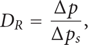
where Δp and Δp s are the pressure gradients for the drag reducing solution and the solvent, respectively. Any fluid whose drag ratio is less than one is a drag reducing fluid. Thus, drag reduction can be defined by

The first commercial application for high polymer drag reduction was its use in the 48-inch diameter 800 mile long Alaska pipeline carrying crude oil from the North slope in Alaska to Valdez in the south of Alaska [5, 6]. Due to the very slow recovery (days) after high shear through a pump, aluminum disoaps were not practical as a drag reducer [7]. Later, drag reduction in aqueous systems using surfactant additives were found to be effective and because of rapid recovery after shear were of interest for recirculation systems. Savins found anionic surfactants were good at drag reducing and stable mechanically [8], but they had precipitation and foam problems [9]. Zakin and Lui [10] found that the effective drag reducing temperature range of nonionic surfactants was very narrow which restricted their application. Chou noted that cationic surfactants had much broader effective drag reducing temperature ranges, recovered rapidly after shear in a pump, and had fewer foam problems, and thus they were more useful [11].
A large number of publications has appeared since the first research paper in 1931. Nadolink and Haigh collected and summarized more than 2,500 references relating the concept of “Skin Friction Reduction” [12]. Ge [13] analyzed 3,800 publications concerning “Drag Reduction” from 1950 to 2007 and found drag reduction research gained much attention from the early 1960s, when polymer drag reduction researches were focused. Drag reduction publications continued to rise and reached a peak around 1977, after the first oil crisis in 1973–1974. By the 1980s, high polymers in both aqueous and hydrocarbon systems [14] were the main research interests. From the 1980s, district heating and cooling (DHC) systems and other potential applications were being developed for energy saving. Correspondingly, research on surfactant drag reduction began to increase. Around 2000, the number of publications each year recovered to the 1977 peak and continued to increase. From 2000 to 2007, publication numbers had the largest increase probably due to rising energy costs. Ge also pointed out that research journal articles made up the majority of the publications, 69%. Patents (12%) have been the second largest contributor, since drag reduction has important practical applications. About 10% of the publications have been reviews, reports, theses, and books.
Since drag reduction has a close relation to energy conservation. It will receive more and more attention as more and more potential applications become practical.
1.2. Applications of Drag Reduction
The application of drag reducing additives (DRAs) is greatly decreasing system energy requirements, reducing pipe diameter, or increasing flow rate, etc. The first famous application of DRAs was in transport of crude oil in the trans-Alaska (TAPS or Alyeska) Pipeline in 1979. The pipeline is 800 miles long with 48-inch diameter. After injecting a concentrated solution of a high molecular weight polymer downstream of pumping stations at homogeneous concentrations as low as 1 ppm [6], crude throughput was increased by up to 30%. Polymer DRAs were also successfully applied in other crude oil pipelines such as Iraq-Turkey, Bass Strait in Australia, Mumbai Offshore [15] and North Sea Offshore [16], and in finished hydrocarbon product lines [17]. In each case, the polymer composition had to be designed for the particular hydrocarbon to be transported.
Polymer DRAs have also been proposed for the following applications: oil field operations [18, 19], slurry or hydraulic capsule pipeline transportation [20, 21], suppression of atherosclerosis [22, 23], prevention of lethality from hemorrhagic shock [24], increased water flow and water jet focusing in firefighting equipment [25, 26], prevention of overflows of water in sewage systems after heavy rains [27], increase of volumetric flow rate of water in hydropower and irrigation systems [28], and as antimisting agents in jet fuel [29].
Drag reducing surfactants (DRAs) can be used in district heating or cooling systems (DHC). These systems provide or remove heat in buildings or a district by a recirculation of water heated or chilled at a central station. The water recirculation energy requirements make up about 15% of the total energy for a DHC. In order to decrease this large proportion of the energy requirements, it is desirable to reduce friction in the water recirculation system. Thus, drag reduction by surfactants is an alternative choice to meet this purpose. Surfactant DRAs can reduce pumping energy requirements by 50–70%. The effectiveness depends on the kinds of additives used and the layout of the primary system. The savings by DRAs are greater if the pipeline has fewer branches or the pipelines are longer or the number of fittings (e.g., valves, elbows, etc) is relatively small [30].
Surfactant DRAs field tests have been carried out successfully in large-scale district heating systems and reduced pipe flow energy significantly. The representative applications are Herning, Denmark [31], Volklingen, Germany [32], and Prague, Czech Republic [33]. Surfactants have been tested in district cooling systems at the University of California at Santa Barbara [34] and in Japan. Takeuchi et al. [35] applied surfactant drag reduction to the central heating/cooling system of the building of the Sapporo City Hall. Saeki reported using cationic surfactant DRAs in practical air conditioning systems for energy saving using ice slurries [36]. Surfactant DRAs were also used to prevent the agglomeration of ice slurries which was also investigated [37]. The combination of the ice-dispersion ability and drag reduction effectiveness improved the performance of ice slurry systems in advanced cold heat storage, transportation, and heat exchange systems [38]. Recently, Saeki reported that cationic surfactants in aqueous systems have bed used in over 130 buildings throughout Japan and reduced pumping energy by 20%≾60% [39].
Besides DHC applications, a novel application of surfactant DRAs is preventing flow-induced localized corrosion (FILC) [40, 41]. Surfactants can not only reduce wall shear stresses at a constant Reynolds number, but also suppress turbulent eddies near the wall, whose repeated impacts cause intermittent stresses on the wall, leading to mechanical damage to the surface material. Another promising novel application of drag reducing surfactant systems is in hydraulic fracturing fluids.
As mentioned above, there are three main kinds of drag reducers: fibers, polymers, and surfactants. Drag reduction by each of these types of drag reducers is reviewed in Sections 2 to 4.
2. Drag Reduction in Fiber Suspensions
Solutions with fibers of aspect ratio (l/d) of 25 ≾ 35 showed drag reduction with high concentration of fibers [42, 43]. With increasing aspect ratio and decreasing fiber diameter, the effectiveness of fibers increases [42–44]. Systems of fibers mixed with polymers achieved up to 95% drag reduction [45, 46]. This drag reduction level is higher than that for polymers or for fibers alone. The polymer in this kind of system was also more resistant to degradation.
Fibers are chemically and mechanically stable in an aqueous environment. Since they are insensitive to water chemistry, piping materials, and temperature, they can be effective over a wide temperature range [42, 47]. Lee and Duffy [44] suggested that fiber drag reduction might be caused by suppression of turbulent eddies in the turbulent core region.
However, use of fibers is limited by the drawback that they can cause plugging problems in pipelines due to the high concentration (as high as a few percent [42]) required for drag reduction.
3. Drag Reduction in Polymer Solutions
Polymer solution drag reduction has been studied extensively in both aqueous and hydrocarbon media by many researchers [48–51]. Some important characteristics of polymer drag reduction are summarized below.
3.1. Drag Reduction Types
Early work proposed two types of drag reduction in dilute polymer solutions [52]. Very dilute solutions display onset drag reduction that is in the fully developed turbulence region, drag reduction only occurs above an onset Reynolds number, where the friction factor decreases below that for ordinary Newtonian turbulent flow. At Reynolds numbers less than the onset value, no drag reduction occurs. Thus, there is an onset shear stress and an onset shear rate.
For more concentrated polymer solutions, drag reduction occurs by extension of the laminar region. In this case, onset conditions are reached at low Reynolds numbers, that is, the laminar-turbulent transition is not observed and laminar-like behavior is extended to an extended laminar region, in which the friction factor is lower than that of ordinary Newtonian turbulent flow at the same Reynolds number. Drag reduction here and also in onset drag reduction increases with flow rate until a critical wall shear stress is reached [49, 53], at which the rate of polymer degradation in the wall region exceeds the rate at which polymer is replenished in this region and drag reduction diminishes.
The main difference between these two kinds of drag reduction is the region where drag reduction occurs. The former begins in the fully developed turbulent region. The latter is observed in the extended laminar region. They were later labeled Type A and Type B drag reduction by Virk and Wagger [54].
The onset phenomenon in drag reduction is discussed below. Some important effects, which affect drag reduction, will also be discussed.
3.2. The Onset Phenomenon
For randomly coiled polymer solutions, drag reduction does not occur until a certain wall shear stress [50, 55] or shear rate [56, 57] is exceeded. This is the onset phenomenon. Its mechanisms are presumably stretching of the polymer molecules in the extensional flow regions or the entanglement of many molecules reaching the size of turbulent eddies [56, 58]. White [59], Virk [50] and Hershey [60] found the onset shear stress was not dependent on pipe diameter. The onset Reynolds number is proportional to the 8/7th power of the pipe diameter. So the same polymer solution has different onset Reynolds numbers in different pipe diameters, reflecting the onset shear stress or shear rate. Therefore, it is more appropriate to define the onset phenomenon using the onset shear stress or shear rate rather than the onset Reynolds numbers which are a function of polymer parameters. It decreases with increase of molecular weight and radius of gyration of the polymer molecules [50].
In predicting the onset phenomenon, researchers proposed three different hypotheses, namely, length scale, time scale, and strain energy storage models. The length scale model was proposed by Virk and Merrill [61] who proposed that onset occurs when the ratio of the polymer length scale (radius of gyration) to the turbulent length scale reaches a certain value. In the time scale model, the onset occurs when the time ratio (or Deborah number) is around unity. The time ratio is defined as the ratio of polymer relaxation time and the turbulent time scale. Most researchers preferred the time scale model because polymer size is several orders of magnitude smaller than the turbulent eddy size at onset, while the polymer relaxation time is about the same order as the turbulent time scale [51, 56, 57, 61]. In the strain energy storage model based on Gaussian bead-spring theory, Kohn [62] proposed that the polymer molecules stored energy when they are strained by high shear stress near the wall, and released it by relaxation when transported to the low shear region at the core. The onset of drag reduction occurs when strain energy convection is comparable to energy diffusion. This model as well as the time scale model predicts a decrease in onset Deborah number as polymer concentration increases which was confirmed by experiment [63]. The length scale model does not.
3.3. Maximum Drag Reduction Asymptote
Early researchers reported the existence of a maximum drag reduction asymptote for dilute polymer solutions. Usually, the maximum drag reduction can be achieved when concentration is tens or hundreds of ppm [53]. Castro and Squire [64] studied two different molecular weights of polyethylene oxide and reported the following equation in power-law form as a maximum drag reduction asymptote:

where C
f
is the Fanning friction factor, Re(
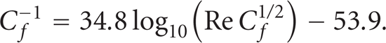
Virk et al. [66, 67] obtained an equation for the maximum drag reduction asymptote (MDRA) by correlating the flow data for different polymer solutions from a number of sources. This MDRA has been most commonly cited by drag reduction researchers and is called Virk's maximum drag reducing asymptote. Different polymer-solvent systems require different polymer concentrations to reach the asymptote. The equation is:
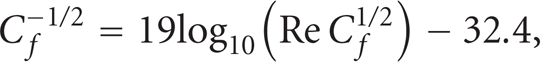
or

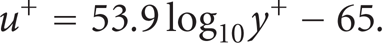
Moreover, Virk et al. [66] derived an ultimate mean velocity profile from (5a). They proposed a model for drag reducing fluids in the turbulent region, analogous to those of Newtonian fluids. It can be summarized in the dimensionless form:
viscous sublayer (0┼y+┼11.6)

core region (y e +┼y+)

where u+ is the dimensionless velocity, y+ the dimensionless distance from the wall, y e + the joint point of the elastic sublayer and the core region, and ΔB the velocity increment from Newtonian flow. u+ is defined as

where u is the time averaged mean flow velocity in the axial direction at a distance y from the wall,
y+ is defined as

where ν is the kinematic viscosity of the fluid.
One can easily compare the velocity profile of a drag reducing fluid to the model and to a Newtonian fluid at any Reynolds number. Virk et al. also proposed a velocity profile asymptote of the ultimate elastic sublayer asymptote (11.6┼y+┼y e +) for polymer solutions at the MDRA condition [66]:

For most polymer solutions, drag reduction curves (both friction factors and mean velocities) are located in a domain bounded by the Newtonian line and by Virk's line. It is interesting to note that some systems other than polymer solutions have reported drag reduction which exceeds this asymptote [45, 68, 69]. The reason for that is the polymer equation was empirically derived from polymer drag reduction data [66]. Zakin et al. [70] proposed an alternate drag reduction asymptote for surfactant systems:

The limiting equation for the elastic sublayer (they found the elastic sublayer expanded to y+ = 15 for surfactant solutions) corresponding to (11) is
3.4. Concentration Effect
Generally speaking, drag reduction at a fixed velocity increases as polymer concentration increases until a certain concentration is reached. This concentration is usually called the saturation concentration. Above this concentration, drag reduction falls off [71, 72]. The initial increase in drag reduction with concentration increase is probably due to the increasing number of polymer molecules which cause the damping of more turbulent eddies. The decrease in drag reduction after the saturation concentration is caused by increase in solution viscosity.
Concentration is quantitatively related to drag reduction effectiveness of randomly coiled polymer solutions. It has a relation to the slope increment, which has been defined as the slope difference between a drag reducing solution and the solvent in a von Karman plot. Virk [73] suggested the slope increment is proportional to the 1/2 power of polymer concentration. Berman and Yuen [74] observed a 2/3 power relation when the polymer concentration is very low (less than 1 ppm).
Many studies on the inhomogeneous drag reduction have been performed. Hou et al. obtained inhomogeneous drag reduction by polymer injection from the slot [75]. White et al. [76] observed that the concentration of polymer is not uniform in the streaks and the spatial distribution of the polymer is related to the turbulent structure.
3.5. Molecular Weight Effect
When molecular weight is less than 105, polymers are generally ineffective for drag reduction [53]. For a given concentration and Reynolds number, drag reduction increases with increasing average molecular weight. Virk [50] concluded that for the same polymer species an increase in molecular weight resulted in a decrease in onset shear stress and in the amount of polymer required to obtain the same level of drag reduction. Paterson and Abernathy [77] pointed out that the highest molecular weight species in the distribution mainly determined drag reducing effectiveness. Berman [78] and Jacobs et al. [79] further studied the molecular weight effect, using modern gel permeation chromatography technique, which allows separation of the high molecular weight portions of the polymer. Their results confirmed the conclusion reached by Paterson and Abernathy [77]. Hunston and Reischman [80] found that the highest molecular weight fraction of polymer primarily determined the onset shear stress. They confirmed this conclusion quantitatively by observing that, when 2.5 ppm of a high molecular weight polystyrene (7.1 million) and 25 ppm of a low molecular weight polystyrene (1.8 million) were mixed, the drag reduction was almost identical to that using the high molecular weight sample alone. However, when the amount of low molecular weight polymer was increased to 100 ppm, low molecular weight polymer made a significant contribution to the drag reducing effectiveness of the mixture. McCormick et al. [81] also suggested that good drag reduction can be achieved by low molecular weight polymers if their concentrations are high enough. However, they also pointed out that there might be a low molecular weight limit for effective drag reduction.
Liaw et al. [82] defined a critical concentration, which separates dilute drag reducing polymer solutions (Type A) and concentrated drag reducing polymer solutions (Type B). When polymer concentration exceeded this critical concentration, a laminar-to-turbulent transition was not observed in their experiments. They also proposed that the ratio of polymer molecular weight to critical molecular weight for entanglements to occur [82, 83] is a useful measure of molecular weight for predicting drag reducing efficiency. According to Liaw et al. [82], good drag reduction was always obtained if the ratio was greater than 50.
3.6. Molecular Conformation and Solvent Effect
Sellin et al. [84] and Hoyt [53] found that linear polymers without branches are more effective drag reducers than other polymers. Polyoxyethylene and polydimethylsiloxane, the two most flexible polymers, are the most effective polymer drag reducers. The effectiveness of polymer solutions depends on the stretching of individual molecules by the stresses in the flow.
The molecular conformation can lead to different types of drag reduction. For dilute less flexible randomly coiled polymers, a transition from laminar to turbulent flow is usually observed and onset occurs in the turbulent region. On the other hand, flexible polymers usually do not show a clear transition. Drag reduction occurs in the extended laminar region. This is probably because the onset shear rate or shear stress has already been reached in the laminar or transition zone [52, 58].
Many workers studied the effect of molecular conformation on drag reduction by changing the interactions between polymer molecules and solvent. Hershey and Zakin [52] found the drag reducing ability of polyisobutylene was better in a good solvent-cyclohexane than in a poor solvent-benzene. They indicated that drag reduction in good solvents, which allow polymer molecules to expand more freely in the solution, is greater than in poor solvents, where the molecule's volume is smaller. Later, Hunston and Zakin [63] reported that the onset phenomenon occurred earlier when polymer molecules were dissolved in a better solvent. Poor solvents also affect the mechanical degradation of polymers. They found that in a poor solvent, mechanical degradation is more rapid than in a good solvent [85].
Virk [54, 86] and Rochefort and Middleman [87] demonstrated that molecular conformation can also be altered by changing the salinity of an aqueous polyelectrolyte solution. They found that polyacrylamide in low salt aqueous medium produced more drag reduction than in high salt solutions in which molecules coiled. The polymer molecules expanded in the former solution due to charge repulsions and coiled in the latter solutions in which charges were neutralized. The molecular conformation of polyacrylic acid can be varied by changing the pH value of the solution. At low pH the polymer molecules collapse due to protonation, while at high pH the molecules expand due to charge repulsions. The pH value reflects the concentration of the hydrogen ion. Parker and Hedley [88] and Banijamali et al. [89] reported greater drag reduction in high pH than in low pH solutions, while Hand and Williams [90] found maximum drag reduction at low PH in PAA-water solutions.
3.7. Diameter Effect
For Newtonian fluids in the turbulent region, the von Karman equation describes flow behavior well. Each Reynolds number corresponds to a specific friction factor. However, for viscoelastic fluids at a given Reynolds number, the same polymer solution in different diameter pipes gave different values of the friction factor. In general, the drag reduction observed in large pipes is smaller than that obtained in small pipe systems [4, 58] because of lower wall shear stresses and shear rates.
Viscoelastic theories predict a 1.1-power dependency of critical solvent Reynolds number on diameter in apparently Newtonian solutions [91]. Hershey and Zakin [52] noted in their experiments that the critical solvent Reynolds number varies with about the first power of diameter, in good agreement with the predictions. Thus, for a solution which has a critical solvent Reynolds number for drag reduction of 100,000 in a 2-centimeter diameter tube, the critical solvent Reynolds number for an 8-centimeter tube would be about 400,000. Thus the larger the diameter, the higher the critical Reynolds number needed to initiate drag reduction.
3.8. Stability of Drag Reduction in Polymer Solutions
Polymers as drag reducers have a serious drawback in that they degrade permanently when subjected to high shear or extensional stress. High molecular weight polymers are particularly sensitive to degradation [49], and the rate of mechanical degradation increases with increasing molecular weight [49, 85]. This disadvantage prevents the application of polymers in recirculation systems where high shear stresses in pumps irreversibly degrade the high molecular weight molecules.
4. Drag Reduction in Surfactant Solutions
In addition to fibers and polymers, surfactants are also effective drag reducers. Their advantage over high polymers is that their nanostructures can self-assemble after breakup by high shear.
4.1. Characteristics of Surfactant Solutions
Surfactants are characterized by amphiphilic structures that consist of a hydrophobic group (nonpolar end) and a hydrophilic group (polar end). In aqueous systems, when the concentration exceeds a certain value, surfactant molecules gather into assemblies with their polar ends headed towards water and the nonpolar ends headed to the center based on the rule “like dissolves like”. The assemblies are called micelles. The critical concentration is called the critical micelle concentration (CMC). Surfactants form micelles in order to minimize the hydrocarbon-water interface.
When surfactant concentration is the same as or slightly above the CMC, the shape of micelles is spherical or ellipsoidal. As the concentration increases, micelles are forced to move closer to each other. This increases the system energy due to electronic repulsions. To keep the system stable at a lower energy level, micelles tend to form nonspherical shapes when the concentration reaches a second critical value (CMCII). While they may form vesicles or disklike shapes in some cases, they may also form long cylindrical shapes, usually called rodlike or wormlike micelles. In the presence of electrolytes, cosurfactants or organic counterions, the charges on cationic surfactant head groups can be partly neutralized or diluted and the micelles can be packed more closely into a rodlike or wormlike shape. Examples of these three materials are sodium halides, alcohols with intermediate chain length, and salicylate, respectively [92–96]. The rodlike shape of micelles is generally considered a necessity for drag reduction [97, 98].
The forces, which hold the surfactant molecules together in micelles, are much weaker than the primary chemical bonds of polymer molecules. But these forces persist even if the micelles encounter strong shear and break up. They reform or self-assemble when the strong shear disappears, while polymer molecules cannot reform after mechanical degradation. Thus surfactants can be used in recirculation systems containing high shear pumps as they self-repair. The characteristics of surfactant solutions are affected by several factors which are reviewed below.
4.1.1. Effects on the CMC and CMCII
The main factors which affect the CMC in aqueous medium are the nature of the surfactant and the presence of added salts, that is, hydrophobic characteristics, hydrophilic group species, and counterion effect. They will be discussed in detail below.
First, the CMC usually decreases with increase in the hydrophobic character of the surfactant. In aqueous solution, the CMC decreases as the length of the surfactant hydrocarbon chains increases up to 16 carbon atoms. The CMC decreases slowly above 16 carbon atoms and may stop at 18 carbon atoms. The CMC for surfactants with double bonds in the hydrocarbon chain is higher than the corresponding saturated chain [99]. For ionic surfactants with alkyl chains and a common hydrophilic group, the CMC decreases by half for each addition of a methylene group to the hydrophobic chain [99, 100]. A relation between the CMC for straight chain ionic surfactants and the number of carbon atoms (N) in the hydrophobic chain was established by Klevens [101]:
where A and B are two positive constants for a particular ionic head group and given temperature. They are tabulated by Rosen [99] based on many results. The value of B (≈0.3) is close to
Second, the CMC is also affected by the hydrophilic group species. Stigter [102] examined the CMCs of five surfactants each having a different type of head group, and proposed that the CMC was higher when the ionic charge on the head group was closer to the α-carbon of the alkyl chain. Head groups with the same charge will generate electrical repulsion, which may be the reason that the CMCs of ionic surfactants are higher than those of nonionic surfactants [99].
Third, the CMC is affected by the counterions, including inorganic salts, aliphatic salts, and aromatic salts. It decreases due to their dispersion of the charge of the ionic head groups thus diminishing their repulsion in the micelle [99]. Underwood and Anacker [103] found CMC had good correlation with the hydration enthalpy and hydration size of the inorganic counterions. They suggested that the most effective anions in promoting micellization are those which interact the least with water. For cationic surfactants, it has been shown that increase in hydrophobicity of the aliphatic counterion resulted in a decrease in CMC [104, 105]. Aromatic acid counterions (such as benzoates, benzenesulfonates, p-methyl-benzoates and p-methyl-benzenesulfonates) can reduce CMC to an order lower than inorganic and aliphatic counterions [104–106].
The CMCII increases very rapidly with temperature [98, 107]. It is reduced at high salt concentrations [108–110]. For example, the CMCII for cetyltrimethylammonium bromide (CTAB) in aqueous medium is approximately 0.3 M (10% by weight) [111, 112]. However, it is reduced to 0.004 M if 0.2 M sodium bromide is added. Rodlike micelles several hundred nanometers long in the 0.004 M CTAB/0.2 M NaBr solution were detected by dynamic light scattering measurements [113].
4.1.2. Effects on Micelle Shape
The major types of micelles are spherical, rodlike, lamellar, and vesicles [99]. The radii of the spherical micelles are approximately equal to the fully extended lengths of the hydrophobic chains [114]. Micellar shape is spherical at the CMC, and the spherical shape is retained even at low concentrations of inorganic salts [113, 115–121]. High salt concentrations can result in micellar-shape transformation from sphere to rod [108–110]. A number of investigators used different experimental techniques to show that the micelles in solutions of high ionic strength are rodlike in shape. Debye and Anacker [108], using static light scattering measurements, found the data for the CTAB/KBr system were well fitted to a rodlike shape rather than a spherical or a disklike shape. Young et al. [122] concluded that the micelles in high concentration salt solutions were rodlike by results from both static and dynamic light scattering techniques. The rodlike shape of micelles was also supported by results from nuclear magnetic resonance [123] and magnetic birefringence [124]. Israelachvili et al. [125] developed a theory of micellar structure. They considered geometry and energy and proposed that the micelle shape was determined by the dimensionless parameter, called the packing parameter, V/(A0L0), where V and L0 are the volume and length of the surfactant hydrophobic chain, and A0 is the optimal surface area occupied by each surfactant head group. According to Israelachvili et al., micelles were spherical for 0┼V/(A0L0)┼1/3, rodlike for 1/3┼V/(A0L0)┼1/2, disklike for 1/2┼V/(A0L0)┼1, and V/(A0L0)>1 gave reversed micelles in nonpolar media. A shape transformation from sphere to rod can be induced by the addition of salt because the salt can reduce A0 by partially screening the electrostatic head group repulsion.
4.1.3. Effects on Micelle Size
Micelle size is affected by many factors, such as the chain structure of the surfactant, the head group of the surfactant, counterions, and temperature, etc. It can be characterized by aggregation number, which is the number of surfactant monomers aggregating to form a micelle. The classical method for determining the aggregation number is elastic light scattering [126]. It has been observed that the aggregation number increases rapidly with increase of hydrocarbon chain length and decreases with increasing head group size [127].
The length of the rodlike micelles increases with decreasing temperature and with increasing concentration of surfactant and salt [109, 113, 128]. Missel et al. [109, 110] observed rapid increases of the aggregation number and the hydrodynamic radius of micelles with increasing surfactant concentration. With an increase in surfactant monomer chain length, micelle length becomes more sensitive to the variations of temperature and salt concentration [110, 113].
For surfactants with a common hydrophobic chain, micelle size decreases with increasing head group size [129]. Geer et al. studied the effect by a light scattering technique. In their study, they sequentially replaced the protons on the decylammonium head group with methyl or ethyl groups. They proposed that the larger head groups tended to make it more difficult for the counterions to approach the charge center and disfavored micelle growth leading to micelle size decrease. Other researchers attributed this effect to the increased difficulty in packing the head groups on the micelle surface [130]. Rehage and Hoffman [131] explained the effects of head groups on micelle shape using geometry. If the area of the hydrophilic head group is larger than that of the hydrocarbon chain, the system will tend to form aggregates with convex curvatures. If both areas are the same, planar structures will be formed. If the head group has an area less than that of the hydrocarbon chain, inverse micelles will be formed.
Salts play an important role in micellar growth. Certain types of salts can strongly affect micelle size. In general, the effect of salt on the aggregation number of rodlike micelles increases with increasing lyotropic number of the anion. Thus, those anions which can more effectively reduce surfactant CMC are usually more efficient in inducing micelle growth. This is because the formation of both the spherical and the long rodlike micelles is strongly controlled by the charges on the surfactant head groups. Salts with greater ability to neutralize these charges are useful for both micelle formation and size [99].
Aromatic acid anions are known to greatly promote micellar growth. The influence of salicylate ions on the properties of cetylpyridinium micelles has been extensively studied by Hoffmann et al. [94, 95, 132–134] using electric birefringence, static and dynamic light scattering, and small angle neutron scattering. They found that, at a concentration of a few millimoles of surfactant per liter, micelles grew to be several hundred angstroms long with a few millimoles per liter of salicylate [97].
4.1.4. Shear Effects
Surfactant solutions are very sensitive to shear. Shear can induce reversible structural transformations in the solution [135]. Shear effects appear as shear thinning, shear-induced structures (SIS), shear-induced phase transitions (in shear bands), gelation, and flow instabilities [136, 137]. The mechanisms of these phenomena are not fully understood. However, these behaviors have both theoretical and practical scientific importance [138, 139].
At low shear rates, surfactant solutions with rodlike or threadlike micelles usually act as Newtonian fluids because micelles rotate freely in the solution. At higher shear rates, micelles start to align in the shearing direction causing shear thinning [139, 140]. A particular phenomenon may occur for some solutions at a critical shear rate at which the shear viscosity and elasticity have a sudden increase. This phenomenon is called shear-induced structure (SIS). The SIS structure is orders of magnitude larger than the individual rodlike micelles [141–146] and the solution is like a viscoelastic gel [147]. However, as shear rate increases, the SIS is no longer stable and viscosity begins to decrease with shear rate. At the viscosity peak, it is believed that micelles are fully aligned in the flow direction. This opinion was confirmed by flow birefringence [140] and small angle neutron scattering experiments [148–151]. The critical shear rate for SIS depends on the surfactant concentration/chemical structure, counterion concentration/chemical structure, temperature, and also on the geometry of the rheological measuring devices [152].
Several authors proposed that SIS may relate to the drag reduction phenomenon in turbulent flow [138, 141, 142, 153]. SIS and phase separation were detected by Koch [154]. He hypothesized that the monomer surfactant concentration increases rapidly with shear causing a coacervate phase to form. Fischer [136] observed oscillations in the first normal stress difference and shear stress indicating that elastic structures were formed and destroyed with SIS and the induced new phase was more elastic than the initial one. Butler [137] observed a new phase generated from the solution at SIS and used the concept of shear banding to distinguish the two phases. Shear banding is usually observed at high micelle concentrations and is characterized by a stress plateau at a critical shear rate. The shear stress becomes independent of shear rate while a second phase appears. As shear rate further increases, shear thinning occurs [98, 155]. In some systems, the proportions of old and new phases change with shear when a second critical shear rate (
Despite the many studies made on the subject, the nature of SIS is not well understood. Its relation to drag reduction needs to be further investigated. It is still unclear whether a universal shear-induced structure indeed exists for different surfactant solutions [153, 157] because there are some surfactant systems that do not show any SIS in the ranges of shear rate studied. However, it appears that in surfactant solutions, SIS is only stable when shear conditions can induce viscoelastic behavior in the solution [145].
4.2. Main Classes of Surfactants in Drag Reduction
There are two broad classes of surfactants, namely, nonionic and ionic surfactants. Ionic surfactants include anionic, cationic, and zwitterionic surfactants.
4.2.1. Drag Reduction of Nonionic Surfactants
Nonionic surfactants do not carry charges. So they are less affected by other ions. This property is an advantage for nonionic surfactants compared to anionic surfactants. But nonionic surfactants only show drag reduction in a narrow temperature range around their coacervation temperature or cloud point. This characteristic limits the usefulness of nonionic surfactants.
Zakin and Chang observed that nonionic surfactants with straight chain alkyl groups were effective. They discovered that some mixtures of nonionic surfactants at 1% concentration were effective drag reducers at temperatures around their cloud point. The mixtures had the chemical structure of C18H35-(OCH2-CH2)n-OH. The cloud point could be lowered by lowering the value of n or by the addition of a multivalent salt such as sodium sulfate. Therefore, the drag reduction temperature range can be lowered to temperatures below the cloud point [159]. Deroussel [160] measured drag reduction on nonionic surfactants containing saturated and unsaturated 12-carbons to 18-carbons alkyl groups with 4 to 23 ethylene oxide groups at 1% concentration. His conclusion was that the temperature of maximum drag reduction is close to the cloud point of the surfactant solution. With increasing length of the alkyl group and decreasing number of ethylene oxides, the cloud point and the effective temperature range for drag reduction could be lowered. The drag reducing effective temperature is also affected by the length of alkyl chain, the number of ethylene oxide groups, and the concentration ratios in mixed surfactant systems. Hellsten and Harwigsson [161] tested two groups of ethoxylated fatty acid ethanolamides, RMA-m and OMA-m. They found the RMA was effective at high temperature and OMA was effective at low temperature. This kind of surfactant is rapidly biodegradable and has low toxicity against marine organisms. They suggested that OMA would be a good candidate for use in district cooling systems (5 ≾ 15°C).
4.2.2. Drag Reduction of Anionic Surfactants
Since the early observations by Mysels et al. [2] of drag reduction by aluminum disoap thickened gasoline, many researchers investigated drag reduction of anionic surfactants in nonaqueous media, primarily lithium, sodium, or aluminum salts of disoaps. They are presently the only known effective surfactant drag reducers in hydrocarbon media. To obtain good drag reduction for this kind of surfactant, the concentration usually needs to be very high (about a few thousands ppm) [162, 163]. This leads to large costs and environmental problems. In aqueous solutions, anionic surfactants form foams with air. Due to their sensitivity to calcium and magnesium ions present in most tap water which cause precipitation, anionic surfactants are not practical for most aqueous applications [47]. Thus they have limited applicability. Savins [8, 164] found that a critical shear stress exists for anionic surfactants in water above which drag reduction was rapidly lost. When the shear stress was reduced below the critical value, drag reduction was completely regained without any delay, different than the permanent degradation of polymer drag reducers under high shear stress.
4.2.3. Drag Reduction of Cationic Surfactants
Cationic surfactants with appropriate counterions are insensitive to cations and show much broader effective temperature ranges. Thus, they have more potential applications. So a great deal of research on cationic surfactants has been carried out since the 1980s. Drag reduction in cationic surfactant solutions is affected by surfactant structure, counterion, and concentration, temperature, which will be reviewed below.
(a) Surfactant Structure Effect. In the family of cationic surfactants, quaternary ammonium surfactants and those with related structure (cetyl pyridinium salicylate) are excellent drag reducers. The first cationic surfactant studied in drag reduction was cetyl trimethyl ammonium bromide (CTAB). White [165] and Zakin et al. [9] tested CTAB with 1-naphthol at different concentrations and found drag reduction increased until a critical wall shear stress was reached and beyond which drag reduction decreased. This is similar to Savins’ conclusion for anionic surfactants. Chou et al. [166, 167] studied three cationic surfactants (Arquad 16–50, Arquad 18–50, and Kemamine Q-2983C) and concluded that the upper temperature limit for effective drag reduction is dependent on the alkyl chain length. When temperature is reduced below the upper critical temperature, drag reduction effectiveness can be regained. Rose and Foster [168] and Chou et al. [169] found the lower temperature limit depends on solubility of the surfactant. Surfactants containing alkyl bishydroxyethyl methyl can provide drag reduction down to lower temperatures compared to those with alkyl trimethyl because the former are more hydrophilic. Unsaturation of the alkyl chain also improves the solubility of long chain surfactants and thus can give drag reduction at low temperature [168, 170, 171]. Chou and Zakin and Lu et al. also studied the drag reduction effectiveness of mixed cationic surfactant systems. They noted that the effective drag reduction temperature range for long hydrocarbon chain cationic surfactants extends to higher temperatures than that for short chains which are effective at lower temperatures. The temperature range can be extended when a long chain surfactant and a short chain surfactant are mixed. The lower temperature limit of the long chain surfactant can be greatly decreased by adding a small amount of short chain surfactant, while the upper temperature limit is only slightly reduced. Thus, cationic surfactants can have wide temperature ranges suitable for both district heating and cooling systems. The effects of mixed counterions were similar but less dramatic [11, 172, 176].
(b) Counterion Effect. Counterions are added to cationic surfactant solutions useful for drag reduction because cationic surfactants would not form long rodlike micelles without counterions to disperse the head group charges. 1-naphthol was the first counterion to receive wide attention. Elson and Garside [173] investigated the counterion concentration effect of 1-naphthol and concluded that the optimum molar ratio of counterion to surfactant was 1 : 1 for high concentrations of surfactant and more than 1 : 1 for low concentrations of surfactant. Sodium salicylate is the most widely studied counterion. Chou et al. [171, 174] found that an Ethoquad O-12/sodium salicylate solution at a molar ratio of 1.5 : 1 showed most effective drag reduction at 2°C. Excess quantities of sodium salicylate (0.2 wt.%) in the cetyl trimethyl ammonium salicylate (CTASal) system (0.2 wt.%) were observed by Rose et al. [168, 170] to increase the critical Reynolds number (from about 20000 to about 50000) and the critical temperature (from 50°C to 70°C). The effectiveness of drag reduction systems can be promoted by hydrophobic substitute groups on benzoate compounds if the hydrophobic substitute groups are widely separated from hydrophilic substitute groups on the same carbon ring. The orientation of counterion molecules at the micelle-water interface is affected by the position of the substituent groups on the benzoate ring. This was confirmed by Smith et al. [175]. Chou [174] and Ge et al. [13, 176] observed increased drag reduction temperature ranges with certain mixtures of counterions. Chou et al. [169, 174] proposed a number of counterions that may be very effective at temperatures between 40°C and 90°C.
4.2.4. Drag Reduction of Zwitterionic Surfactants
Because cationic surfactants are not easily biodegradable, zwitterionic surfactant or combinations of zwitterionic with anionic surfactants have been studied as drag reducers. Zwitterionic molecules have both positive and negative charges on different locations of the molecules. Zwitterionic/anionic mixtures containing up to 20% anionic are most effective drag reducers [177]. However, despite their potential as drag reducing agents, only limited studies of them have been carried out. Hellsten and Harwigsson [178] reported on a mixture of 2.5 mM alkylbetaine/0.5 mM SDBS which was effective as a drag reducer from 6 to 60°C for C16 and from 20 to 100°C for C18. Zhang et al. [179] determined that an Akzo Nobel alkyl ammonium carboxylate (zwitterionic)/SDBS at molar ratio 4 : 1 was effective as a drag reducer in both water and ethylene glycol/water systems. At low temperatures, they reported that surfactant containing the oleyl group was even more effective because of better low temperature solubility.
4.3. Diameter Effect
It is important to study scale-up to predict drag reduction performance in large pipes from small diameter measurements because most practical flow systems use larger pipes than those in the laboratory. However, while the friction factor for Newtonian fluids can be predicted from the Reynolds number, the friction factor for drag reducing fluids is a function of both Reynolds number and pipe diameter. Some research relating polymer drag reduction scale-up was noted in Section 3.7. A few scale-up studies on surfactant drag reducers are reviewed below.
White [165] observed that the critical wall shear stress was independent of pipe diameter. Gasljevic et al. [180] found that drag reduction of Ethoquad T 13/27 (2000 ppm)/NaSal (91740 ppm)+3.75 mMol/L of Cu(OH)2 in pipes with five diameters (2 mm, 5 mm, 10 mm, 20 mm, and 52 mm) was independent of tube diameter when plotted against bulk (mean) velocity up to the wall shear stress corresponding to maximum drag reduction. They also suggested that surfactant drag reduction scales even better with solvent shear viscosity.
4.4. Stability of Drag Reduction in Surfactant Solutions
Savins noted that drag reduction for anionic surfactants was regained when the shear stress was lowered [8]. The loss of drag reduction was presumably caused by breaking up of the micelle nanostructure due to high shear stresses. No permanent degradation was found after 88 hours of continuous shear above the critical wall shear stress. Zakin and Lui [10] found mechanically degraded nonionic surfactant solutions quickly regained their drag reducing ability after passing through a pump. White [165] and Zakin et al. [9] found cationic surfactants that showed no permanent mechanical degradation. These findings are important for surfactant drag reduction applications and make surfactants good agents for recirculation systems in which the fluid is repeatedly passed through pump.
5. Heat Transfer of Drag Reducing Surfactant Solutions
Along with drag reduction, the heat transfer ability of surfactant solutions is also reduced significantly [84, 170, 181–189]. Aguilar et al. [183] showed that the reduction of heat transfer is always a little larger than drag reduction. In a tube-in-tube heat exchanger, Christensen and Zakin [188] found that the heat transfer reduction of a Kemamine Q-2983C/NaSal (2000 ppm/2200 ppm) drag reducing surfactant solution could reach as high as 90%. Heat transfer reduction of drag reducing solutions is beneficial in transporting crude oils that need to be heated to keep them flowing. It reduces the need for heat insulation materials on long distant pipelines. However, for DHC systems, the heat transfer reduction is a major problem since heat exchange in DHC is very important. Thus, techniques for enhancing heat transfer of drag reducing surfactant solutions must be developed for DHC systems.
5.1. Reasons for Heat Transfer Reduction
The mechanism of heat transfer reduction of drag reducing surfactant solutions is still not totally understood. However, it may be attributed to two characteristics observed in turbulent drag reduction flows.
As mentioned in Section 3.3, the viscous sublayer of drag reducing solutions is extended compared to Newtonian fluids. Sellin et al. [84] suggested that this extended viscous sublayer increases the thermal resistance between wall and bulk fluid and therefore decreases the heat transfer ability of the solution.
Another characteristic is that velocity fluctuations of drag reducing surfactant solutions in turbulent flow in the radial and tangential directions are greatly suppressed compared with Newtonian fluids [190–195]. It is postulated that velocity fluctuations in the radial direction are strongly related to the heat transfer ability of the fluid. Thus, heat transfer in the radial direction is greatly reduced because of the decrease of radial velocity fluctuations.
5.2. Methods for Enhancing Heat Transfer Ability
There are two methods to enhance the heat transfer ability of drag reducing surfactant solutions by overcoming one or both of the two possible reasons for heat transfer reduction in Section 5.1. One is to modify the inner surface of heat exchangers to cause disturbances to the viscous sublayer of drag reducing flows. Another is to temporarily destroy or alter the surfactant nanostructure by mechanical or other means at the entrance to the heat exchanger to obtain Newtonian, water-like flow behavior in the heat exchanger. Self-assembly of the micelle nanostructure downstream of the heat exchanger would restore drag-reducing behavior in the pipeline flow.
5.2.1. Modify Inner Surface of Heat Exchanger
Plate heat exchangers and fluted tube-in-tube heat exchangers can enhance the heat transfer ability of drag reducing solutions very effectively. Plate exchangers generate high shear stress and their convoluted paths can cause extensional flows both of which can cause micelles to break up. The special inner surface of fluted tubes enhances the heat transfer ability of surfactant solutions by altering the viscous sublayer [181, 188]. In the fluted tube-in-tube heat exchanger [181], the spiral wall generates a swirling motion and extra shear stress on the fluid. Both the high shear stress in the fluted tube and the swirling motion increase the heat transfer ability of the solutions.
Kishimoto et al. [196] and Sato et al. [197] investigated heat transfer of drag reducing surfactant solutions using a spiral grooved rough inner tube, a two-dimensional fence plate, a saw-toothed plate, and a porous plate. They found heat transfer enhancement can be achieved by changing the geometry of these heat transfer exchangers. Investigators at the UMSICHT Institute in Germany tried to enhance heat transfer by inserting spring coils inside the inner tube of the heat exchanger. But this method was not effective [198].
While some of these methods enhanced heat transfer, the pressure drops of drag reducing surfactant solutions passing through these exchangers are higher than straight tube-in-tube heat exchangers due to their tortuous paths. This is the price that must be paid. However, compared with other heat transfer enhancement methods, the pressure drop penalty in fluted tube-in-tube heat exchangers is small [181]. Thus the fluted tube method is most applicable for heat exchangers in new DHC systems. The economic viability of these methods depends on the ratio of capital costs to operation costs and the ratio of heat transfer ability to pressure drop penalty. All of these depend on DHC design and user requirements.
5.2.2. Destruction of Nanostructure in Heat Exchanger
Five different methods have been proposed to break up the micelle nanostructure in drag-reducing surfactant solutions before a heat exchanger.
The first method is to position a pump at the entrance of the heat exchanger. The pump provides high shear which would temporarily destroy the surfactant nanostructure and enhance heat transfer in the heat exchanger. This is the most convenient method but may not be possible for existing DHC systems or for many newly designed systems.
The second method is to use ultrasonic energy to destroy the surfactant nanostructure at the heat exchanger entrance. While this method does not impart additional pressure drop penalties to the flow as it does not change the flow field, however, it does take a great deal of energy to breakdown the micelle nanostructure and it is difficult to transmit ultrasonic energy effectively to a large-scale flowing system [199, 200].
The third method is by insertion of small destructive devices such as static mixers, honeycombs, or meshes at the entrance to the heat exchanger [184, 201–203]. This method is similar to the first method. The destructive devices can generate large shear and extensional stresses on the surfactant solution to destroy the micelle nanostructure. This method is easy to install and uninstall in existing systems and should be inexpensive. However, it may cause large pressure drop penalties. In a similar approach, Li et al. [204] studied the effectiveness of three types of wire meshes. Heat transfer enhancement largely depended on the Reynolds number and concentration of surfactant.
Drag reduction recovery times for these methods depend on the temperature, chemical structure, and concentration of the surfactant [182] as well as the counterion. The self-repair time of surfactant nanostructures can be estimated from measurements of pressure gradients of the flowing solution downstream from the destructive devices.
The fourth method is to increase wall shear stress in the heat exchanger above the critical wall shear stress for surfactant micelle break up. Pollert et al. [205] noted that when the flow velocity of the solution through a heat exchanger reaches a certain level, heat transfer enhancement is observed. Thus increasing the flow velocity of surfactant solutions at the entrance of or inside the heat exchangers so that the critical shear stress is exceeded will also destroy the micelle nanostructure.
Wollerstrand and Frederiksen [198] tested this method by installing small diameter tubes or orifices. Kishimoto et al. [206] also tested it by increasing the flow velocity at the entrance of the heat exchanger by decreasing the tube diameter (from D i = 14 mm to 10 mm and 8 mm, resp.). Heat transfer enhancement was observed for an Ethoquad O/12/NaSal solution at a flow velocity above 1.5 m/s in the small tube but a large pressure drop penalty was incurred. Moreover, this approach is probably not practical for existing DHC systems because of the difficulty of tube replacement.
The fifth method is to use photorheological (PR) surfactants as drag reducers. All of the methods above require large energy input and major changes in the flow field. The ideal result would be to reduce drag reduction ability in the heat exchanger to enhance heat transfer and then regain their drag reduction ability at the outlet of the heat exchanger without large energy input. Recently, Raghavan's group has developed new photorheological counterions which are commercially available and relatively inexpensive [207–209]. One of their new PR counterions is the sodium salt of trans-O-Methyl-o-coumaric Acid (trans-OMCA). They found the trans-OMCA/CTAB system is viscoelastic but, when the trans-OMCA is photoisomerized to cis-OMCA by irradiation with ultraviolet (UV) light, the fluid viscosity is largely reduced and viscoelasticity is lost. This is because the change in the counterion from trans to cis configuration causes micelles to rearrange into much smaller ones. Shi et al. [210] found cationic surfactant solutions with trans-OMCA have good drag reduction, while the solutions with cis-OMCA are not drag reducing. Thus irradiating trans-OMCA or a similar functional chemical counterion can enhance heat transfer but it is necessary to convert the cis-OMCA back to trans-OMCA to regain drag reduction behavior downstream from the heat exchanger. They are exploring other PR systems.
This method requires a balance of heat exchanger length, UV dosage, with low energy requirements surfactant nanostructure recovery time and control of the surfactant solution flow rate to achieve high heat transfer enhancement.
Determination of which heat transfer enhancement method is most practical for drag reducing surfactant solutions in a DHC system depends on the nature of surfactant solution, the temperature range, and the size of the DHC system, and so forth. Minimum additional equipment and energy penalty costs and maximum heat transfer enhancement effects are the targets of future studies.
6. Concluding Remarks
From the summary above, further drag reduction research on mechanism and application covering fields, such as fluid mechanics, heat transfer, turbulence, rheology, and chemistry, is needed to develop surfactant systems useful for DHC and other applications. Advanced experimental methods (such as particle image velocimetry) combined with advanced numerical methods (direct numerical simulation, large eddy simulation, proper orthogonal decomposition, etc.) are among the future directions for research. Field tests of drag reduction and heat transfer are also needed to evaluate the economy and efficiency in practical applications.