
Abstract
Underwater acoustic sensor networks (UWASNs) are playing a key role in ocean applications. Unfortunately, the efficiency of UWASNs is inferior to that of the terrestrial sensor networks (TWSNs). The main reasons are as follows: (1) UWASNs suffer long propagation delay; (2) UWASNs are limited by the narrow bandwidth. Many MAC protocols are proposed to improve the efficiency of UWASNs. However, their improvement is not enough. Moreover, few of them consider the reliability of UWASNs even though the packet loss can fail the applications. Actually, a few of the protocols employ the traditional acknowledgment (ACK) mechanism, but they suffer the throughput degradation a lot. In this paper, first, we propose a protocol called RAS, a priority scheduling approach for multihop topologies. RAS is more efficient in throughput and delay performance. Then, we propose a reliable RAS called RRAS that obtains a tradeoff between the reliability and the efficiency. RRAS designs an ACK and retransmission mechanism, that is, different from the traditional one so that it can maintain a comparable throughput when improving the reliability. Extensive evaluations are conducted to verify that RAS is efficient and RRAS is a tradeoff on reliability and efficiency.
1. Introduction
As a crucial ingredient of cyber physical systems, wireless sensor networks (WSNs) facilitate the interactions between human beings and the physical world through sensing, monitoring, and controlling. Being a type of wireless sensor networks, underwater acoustic sensor networks (UWASNs) [1] draw a lot of interest in ocean applications, such as ocean pollution monitoring, ocean animal surveillance, oceanographic data collection, assisted navigation, and offshore exploration, UWASN is composed of underwater sensors that engage sound to transmit information collected in the ocean. The reason to utilize sound is that radio frequency (RF) signals used by terrestrial sensor networks (TWSNs) can merely transmit a few meters in the water [2].
While UWASNs and TWSNs are similar, there still exist many differences that make UWASNs less efficient than TWSNs [1–3]. First and most importantly, the propagation delay of UWASNs is far larger than that of TWSNs. Acoustic signals propagate at about 1500 m/s underwater, while RF signals travel at the speed of light in the air. To transmit a data packet over 1500 meters, it takes 1 s underwater and 5 μs in the air. Due to the high propagation delay of acoustic signals, the network performance of UWASNs cannot be achieved as highly as that of TWSNs. Second, the sound bandwidth is much narrower than RF bandwidth (e.g., 10 kbps Versus 10 Mbps). Consequently, we should utilize the bandwidth in UWASNs more efficiently. Third, the acoustic sensor is more expensive than the terrestrial sensor, and thus, the sensor deployment in the water is more sparse. The average distance among acoustic sensors is usually several hundred meters.
Many existing methods aim at collision avoidance and improving the efficiency of UWASNs, but they are not reliable. APCAP [2] utilizes the maximum propagation delay to avoid collisions and MAC level pipelining to increase efficiency. To avoid the poor throughput caused by using maximum propagation delay, Peleato and Stojanovic apply a shorter delay to avoid collision when the communicating nodes are close to each other [4]. In addition, two ALOHA-based MAC protocols [5] improve the efficiency by reducing the RTS/CTS handshaking and avoiding collisions with the information from the overheard packets. Although all these MAC protocols help improve the efficiency of UWASNs, none of them consider acknowledgments (ACKs) or retransmissions. Since the packet loss may fail the applications, it is very important to maintain a certain level of reliability with ACK and retransmission mechanisms. For example, when a fire breaks out, such event report packets should arrive at the BS in time. Since they may be lost due to the volatile environment, they should definitely be equipped with retransmission scheme.
On the other hand, existing methods that include ACK mechanisms are not as efficient as the previous techniques with no ACK mechanisms. For example, slotted FAMA [6], UW-FLASHR [7], and the reservation MAC protocol proposed in [8] realize the traditional ACK technique, but they focus on collision avoidance rather than on ACK and the retransmission effects.
Due to the volatile wireless environment, packet loss is very common in UWASNs [1, 9]. Unlike packet collision that can be reduced or manipulated at a very large extent, this kind of packet loss is out of human control. As a result, we should implement ACK mechanism and the corresponding retransmissions so as to improve the network and application reliability. Considering the innate inferior performance and low bandwidth of UWASNs, we should also avoid deteriorating the efficiency too much by enabling ACK and retransmissions. In this paper, to improve the network efficiency, we first design a protocol called RAS (routing and application-based scheduling protocol), based on which we propose a reliable RAS called RRAS to achieve a tradeoff between the reliability and the efficiency.
RAS enables parallel transmissions and utilizing the information from both the routing and application layer it is an efficient priority scheduling at the MAC layer of the base station (BS) [10]. However, it does not require the global positions of all nodes, because it calculates the rough propagation delays between every node pair in the network through the initial synchronization packet exchange that is proposed by Tracy and Roy [8]. Different from RAS whose period is composed of working portion and sleeping portion, RRAS divides the sleeping portion into a NACK-retransmission portion and the sleeping portion. The NACK-retransmission mechanism of RRAS can improve the network reliability.
We summarize our contributions as follows:
We design an efficient priority scheduling protocol called RAS at the MAC layer of BS. We propose RRAS to improve the network reliability. Extensive evaluations are conducted to show that RAS is efficient, and RRAS achieves higher reliability than RAS while achieving comparable throughput performance.
In the remainder of this paper, Section 2 describes related work. As the basis of our new protocol RRAS, the RAS protocol is introduced in Section 3. RRAS protocol is designed in Section 4, and its performance is evaluated in Section 5. Finally, Section 6 concludes the paper.
2. Related Work
Recently, there are extensive research efforts focusing on improving the performance of UWASNs, which are surveyed as follows.
Slotted FAMA [6] is a handshaking-based protocol designed to avoid collisions caused by the hidden terminal problem in UWASNs. It synchronizes all nodes and makes all the transmissions start at the beginning of a slot. The slot length is the sum of the maximum propagation delay and the transmission time of a CTS (clear to send) packet. While it can efficiently avoid collision caused by the long propagation of UWASNs and also enable ACK mechanism, it does not utilize the long propagation delay to improve the throughput and delay performance. Our RAS can achieve higher efficiency with a compact schedule that allows high-level parallelization.
The reservation MAC protocol proposed in [8] avoids collisions and improves the bandwidth utilization by employing two channels: a control channel for RTS/CTS handshake and a data channel for data transmission. It increases the network throughput by dividing a larger group of collision sources into smaller ones. While it realizes traditional ACK technique, it does not investigate the retransmission effects. In addition, it is based on a single-hop topology, and the gateway is in charge of the control packet and data packet coordination. Hence, this MAC protocol does not suit the multihop situation, whose complexity requires a different analysis. In contrast, both RAS and RRAS can be applied in either one-hop or multihop topologies.
APCAP identifies that the traditional CSMA leads to poor performance in UWASNs due to the long propagation delay [2]. Therefore, it utilizes the maximum propagation delay to avoid collisions. To avoid the poor throughput caused by such method, Peleato and Stojanovic reduce the delay used to avoid collision [4]. In addition, APCAP employs MAC level pipelining to increase efficiency. Another MAC protocol UW-FLASHR [7] also implements MAC level pipelining. The difference is that APCAP is based on an adaptive and distributed RTS/CTS handshake while UW-FLASHR employs both TDMA mechanism and RTS/CTS handshaking. APCAP do not consider acknowledgements (ACKs) for the data packets while UW-FLASHR enables traditional ACK mechanisms.
Regarding the RTS/CTS handshaking transmission model as inefficient in UWASNs, Chirdchoo et al. propose two ALOHA-based MAC protocols [5]. This MAC protocol also requires the knowledge of propagation delays between every node pair in the network. Then, it uses the information from the overheard packets to avoid collisions. Its simple and clever mechanisms improve the efficiency, but it does not consider ACK mechanisms, either.
Since packet loss is very common in wireless sensor networks [1, 9], our RRAS can greatly improve the network and application reliability.
3. RAS Protocol
The main purpose of RAS is to design an efficient schedule for all the sensor nodes on when to send and receive DATA packets. First, we introduce the RAS process. Then, we focus on the schedule calculation.
3.1. Overview of RAS Protocol
The typical application we discuss is the ocean bottom surveillance application, in which all nodes generate the same amount of data and send them to the BS periodically with cycle
Before schedule calculation, RAS needs synchronization in the networks. Although there exist many synchronization methods [11, 12], for the sake of simplicity and low cost, RAS only requires coarse synchronization through the initial packet exchange or the information piggybacked in the received packets as The authers in [7, 8] do. Meanwhile, it can calculate the rough propagation delays between nodes by checking time stamps during the synchronization process [8].
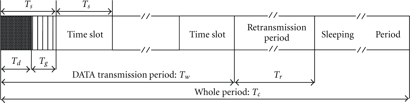
With synchronization, the nodes can work and sleep periodically [13]. In Figure 1, the RAS cycle

RAS cycle.
It is practical to employ static routing, because the networks are static. In addition, the monitoring applications only require data transmissions from the sensor nodes to the BS. Then, the BS calculates the number of data to be transmitted and received at each node. Finally, the BS can calculate for all the sensor nodes the working schedule on when to send and receive data, and broadcast the schedule to all the sensor nodes to follow for a long time. The steps are shown in Algorithm 1.
(1) Coarse synchronization through the initial packet exchange (2) Calculate the rough propagation delay between nodes through the previous packet exchange (3) Calculate static routing (4) Calculate the number of data to be transmitted and received at each node (5) CalcSchedule() /*Algorithm 3*/ (6) The BS broadcasts the routing table and the schedule to all its children with high power
Algorithm 1: RAS protocol at the BS (it runs at the initialization phase).
These processes cost little efforts, because they do not require frequent updates. Therefore, the major goal is how to make the working period of the whole network as short as possible so as to save the energy and improve the network efficiency, that is, how to design an efficient schedule for a cycle.
3.2. Scheduling Principles
The transceiver cannot receive when it is transmitting, and collision will occur at a node when it receives more than one packet [14]. (This corruption is called interference. Interference packets at a node are divided into two types: the first type is for packets that are not destined for the node but are within the node's communication range A DR duration must not overlap any DT duration. A DR duration must not overlap any IR duration. A DR duration must not overlap any other DR duration. A DT duration and IR duration(s) can overlap.
Since there is no data from the BS to sensor nodes, we can design a compact schedule by only allocating time for data from sensor nodes to the BS. Thus, the next principle is as follow:
No DR from ith hop node to (
The goal of data transactions is to guarantee successful receptions, and we arrive at the last principle.
A node considers DR duration as the scheduling basis rather than DT or IR duration.
With DR as the scheduling basis, we do not have to consider whether IR will overlap other IRs and DTs. In addition, we can increase the throughput and reduce delay by making nodes transmit or receive instead of idling whenever no DR is overlapped.
3.3. Scheduling of RAS Protocol
To accomplish the goal of an efficient schedule, RAS implements MAC level pipelining by interlacing multiple data transmissions in a schedule as long as no collision is triggered. During the interlacing process, RAS assigns the slots to nodes with heavier traffic first that is, nodes with heavier traffic are given higher priority in data transmission and reception, and thus other nodes can only transmit or receive in the time slots that are not taken up by the heavier-traffic nodes. In this way, the traffic load can be better balanced, and the efficiency can be improved as well.
We call the schedule length calculated with RAS as
According to scheduling principle (6), we will schedule all the elements generated in a cycle equals by scheduling all the data receptions in a cycle. Let
Step 1:
Schedule the BS's DR from 1-hop nodes.
Step 2:
Schedule the DR tier by tier: from inner tier to outer tier, that is, from DR of nodes in
Step 3:
For each node
The reason to schedule the BS's DR first is that the topmost goal is for the BS to receive all the data generated by all other nodes in a cycle. The reason to prioritize the inner tier nodes over the outer tier nodes is that the inner-tier nodes are affording much heavier traffic. It is unfair for them to share the same bandwidth with other light-traffic nodes. In addition, the packets forwarded by the inner tier nodes are forwarded more hops than those forwarded by the outer tier nodes. Colliding or dropping those packets would cost more efforts to retransmit. Finally, to alternate the receptions among the children provides load balancing of the nodes. If fairness is not considered for a parent's children, a few children might drop packets due to congestion, whereas other children's queues are far from full. Therefore, when we alternate the children's transmissions, we improve the fairness. The three steps are shown in Algorithm 2. How RAS works at the sensor nodes is shown in Algorithm 3.
(1) Parent = BS; hop = 1. //schedule the BS's DR from 1-hop nodes (2) (3) (4) (5) (6) With global information, Parent searches its entire children to alternatively find a child whose transmission results in its reception at the Slot. (7) (8) schedule the child's transmission and the related reception and interference. (9) break searching. (10) (11) (12) Parent fetches the next Slot for reception. (13) (14) fetch the next Parent to schedule reception. (15) (16) hop = hop + 1. //schedule the DR tier by tier (17)
Algorithm 2: CalcSchedule() function at the BS.
(1) Node x receives routing information and a schedule from the BS. (2) Synchronization. (3) (4) (5) sleep until working period starts. (6) (7) (8) request x's parent to wait for data in sleeping period. (9) (10) (11) receive the data as scheduled. (12) (13) (14) send the data in working period as scheduled. (15) (16)
Algorithm 3: RAS protocol at the other nodes (it runs at each sensor node after the initialization).
3.4. Analysis of the RAS Scheduling Algorithm
The time used to calculate the schedule of RAS is less than 1 sec in our personal computer, because RAS is a heuristic method with complexity O(N) in which N is the node number.
Since the upper bound for the RAS schedule length (
4. RRAS Protocol
Since packet loss is very common in UWASNs [1, 9], RAS is not reliable. By enlarging the guard time, we can avoid collisions caused by imprecise synchronization. Hence, in our case, we focus on the packet loss caused by the volatile wireless environment. Because RAS does not considering the ACK and retransmission problem, we propose a reliable RAS called RRAS. RRAS employs the RAS scheduling to transmit all the data efficiently. For the data packets lost during the scheduling, RRAS utilizes the NACK-retransmission mechanism to improve the overall system reliability.
4.1. Overview of NACK-Retransmission Mechanism
In the scheduling of RAS, each node n knows
Retransmission period is part of an RRAS cycle as shown in Figure 2. RRAS cycle is designed from RAS cycle: the data transmission period of RAS is kept, while the sleeping period of RAS is divided into the retransmission period and a shorter sleeping period. In this way, the data lost in data transmission period
RRAS cycle.
The packet loss caused by the volatile wireless environment is random, thus we do not know which packets will be lost in the data transmission period
During retransmission period
4.2. Retransmission Mechanism
The more times that node n retry the transmissions, the higher the reliability is. Although such retransmission is aimed at improving the data transmission reliability, it does not promise 100% success which would cost a lot of extra resources. Hence, in our case, we only focus on one-time retry rather on the frequently used three-time retry [13]. If we want to retry a second time, we can simply add another retransmission period to retransmit the data packets lost during the first retransmission period.
After receiving NACK, node c would retransmit the lost data packets in a batch or in a burst to node n. Since the control frame exchanges deteriorate the UWASN efficiency greatly, batch data transmission improves the retransmission throughput and delay performance by reducing the exchanges.
As for the collision avoidance, in order not to degrade the efficiency, we do not use the maximum propagation delay to avoid collisions as [2, 6] do. In addition, carrier sense and RTS/CTS handshaking are efficient in a network where the propagation delay is negligible, but they are inefficient in UWASNs [16]. As a result, we adopt a simple ALOHA mechanism [5, 17]. According to [10], the propagation time is usually larger than the data duration time (100 ms) as long as the distance between the nodes is larger than 150 m. In this situation, even if the two nodes send packets to each other simultaneously, no collision happens. Furthermore, if node A and node B start to send a packet to C at the same time, as long as the difference between A–C distance and B–C distance is larger than 150 m, there will be no collision at node C. For these reasons, we employ simple ALOHA that is, a node could transmit a packet when it is not receiving or transmitting. Although this mechanism does not guarantee collision-free situations, it is more efficient. In case collision happens, further actions can be taken: retransmit the collided packets again or ignore it and accept the current reliability level. In our work, we study the effects of ALOHA through experiments and prove its influence on the efficiency and reliability.
We define the states of a node after the data transmission period as

A node might be in 4 situations: (N,N), (N,Y), (Y,N), and (Y,Y). If it it in state (N,N) with no packet loss, it is free from sending or receiving packets. If it is in state (N,Y), it does not know that its data transmissions to its parents are lost until it receives the NACKs from its parents. In this case, it will only retransmit the data packets designated in the NACKs.
If it is in state (Y,N), it knows that data transmissions from its child nodes are lost. It is also aware that since it fails to forward the lost packets to its parent nodes, its parent nodes will require them through NACK. It should first ask its child nodes for the lost packets by sending NACKs to them. Next, after collecting the lost packets from its child nodes, it should forward them to its parent nodes. Since it does not know the
The actions in state (Y,Y) is similar to those in state (Y,N). The only difference is that the node should send the lost packets from both its child nodes and from itself to its parent nodes. In summary, the retransmission will be triggered only after receiving the NACK requirements.
4.3. Retransmission Time
In addition, the length of
Given packet loss rate R, to ensure that the time duration is long enough for retransmitting the lost packets, the length of
To make sure that
If a DATA transmission from node a to its parent b is lost, then all the nodes in the route need to retransmit the lost data to the BS. A node will retransmit only on receiving the NACK requirement, then a retransmission between a pair of nodes would take at most

The ALOHA retransmission mechanism only restricts the order between the NACK and its corresponding retransmission that is, it allows parallel transmission among NACKs from different nodes. As a result, the time used is much less that is,
We then consider the case that more than one packet are lost in such a route. The worst situation is that all the packets are lost on the way from a to b. The batch DATA transmission mode reduces the NACK-retransmission handshake, and keeps the handshake round to be 1 among a node pair. Hence the longest time taken for retransmitting all the DATA to the BS is


Next, consider the case that more than one route,

5. Performance Evaluation
The protocol performance is simulated using the parameters shown in Table 1. We use the ns2 setdest tool to generate networks with size ranging from 9 nodes to 64 nodes [20]. For example, the 64-node network covers a 5 km by 5 km area, and it is connected without holes. The maximum one-way propagation time is 1000 ms calculated from the 1500 m transmission range and sound speed.
Parameters for data transmissions.
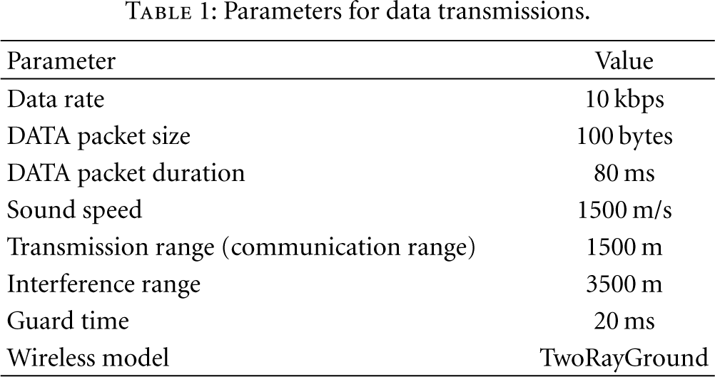
The efficiency performance of RAS is compared with UW-FLASHR [7]. The efficiency and reliability performance of RRAS is compared to RAS and the traditional CSMA/CA used in TWSNs. UW-FLASHR uses control frame handshaking to reserve parallel transmissions. RAS does not employ ACK mechanism, and the traditional CSMA/CA does not adjust the collision avoidance method for UWASNs.
5.1. Schedule Length
Since RRAS uses the schedule of RAS, this section is about RRAS and RAS schedule length. We calculate the lower bound schedule length

Schedule ratio.
Basically, the larger the guard time, the longer the schedule length. Longer guard time allows more imprecise synchronization while reduces the network efficiency. Figure 4 shows the relation between the guard time and the schedule length for ten 64-node networks. In accordance with our expectation, the schedule length increases linearly with the guard time ranging from 25% of the data duration time (80 ms) to 300% of the data duration time. Therefore, if we deploy a network with high clock drift, we should set the guard time to a longer value. Otherwise, we can use a smaller guard time.

Schedule length.
5.2. Throughput of RAS
Due to RAS's high scalability in schedule length demonstrated in the previous subsection, we use the schedule calculated for the case when only one packet is generated in a cycle since this subsection.
To compare RAS with UW-FLASHR [7], an existing MAC protocol designed for high channel utilization, we employ their throughput definition. Throughput is defined by measuring the total number of the intended data packets received by the BS by the total number of data packets generated by all the nodes in a period. Obviously, if the traffic generated at each node is so heavy that it exceeds the maximum capacity of the network, then the throughput would drop and even approaching to 0. Conversely, if the traffic is light, then it is likely that all the data generated will be received by the BS; therefore, the throughput is 1 when there is no traffic.
Although we simulated networks of different sizes, for the sake of conciseness, Figure 5 only compares the throughput of RAS and UW-FLASHR in 36-node networks and 64-node networks. As the traffic rate increases, the throughput of all the networks drops from 1. In addition, 36-node networks are able to afford a much heavier traffic rate than the 64-node networks, because networks with a larger size suffer higher total traffic. Moreover, we notice that the throughput for 36- and 64-node networks with UW-FLASHR dramatically drops from 1 when the traffic rate is not 0. This is because UW-FLASHR performs the slot requirement among the neighbors, and the hidden terminal problem leads to some slot establishment which might cause collisions. On the other hand, RAS performs scheduling based on all nodes' position information, thus no collision happens. Finally, for UW-FLASHR, the heaviest traffic rate these networks could afford is much less than that of RAS. This is because RAS generates a much compacter schedule than UW-FLASHR. RAS arranges the exact time needed by the transmission and reception of each node, while UW-FLASHR reserves the time slots for transmission randomly.

Throughput.
5.3. Average End-To-End Delay of RAS
The end-to-end delay is the period from the time a packet is generated by a node until the time it is received by the BS. Figure 6 shows that the average end-to-end delay increases when the traffic rate increases. Specifically, when the traffic rate is heavy enough to cause congestion in the networks, there are sudden jumps of delay as observed in the figure. By observing the sudden jumps in delay, we find that RAS networks can afford about 4 times higher traffic load than UW-FLASHR networks without collision. Because the scale of 36-node networks is smaller than 64-node networks, their end-to-end delay is also shorter. In addition, when heavily congested, the delay of RAS networks and UW-FLASHR networks stops increasing with traffic rate. The reason is that both RAS and UW-FLASHR are based on TDMA to reserve the channel rather than on CSMA/CA to compete the channel, thus the delay reaches an upper bound. However, the delay upper bound of RAS networks is higher than that of UW-FLASHR networks, this is due to the fact that: the priority scheduling makes the queue utilization of RAS networks higher than that of UW-FLASHR networks (this will be explained in the following subsection). In UW-FLASHR networks, the queue utilization is very low. Most packets from faraway nodes cannot arrive at the BS before being dropped by the heavy-loaded forwarding nodes. In other words, most of packets that arrive at the BS are generated by nearby nodes, thus the delay upper bound is lower. In contrast, this phenomenon is alleviated by the priority scheduling in RAS networks.

End-to-end delay.
5.4. Average Maximum Queue Length per Node of RAS
In this subsection, we demonstrate the advantage of RAS in fairness by showing that its queue utilization is fairer than that UW-FLASHR. The queue size of each node is set to 50 in the simulations. If a queue is filled with 50 packets, then further packet arrival will cause one packet to be dropped.
The sudden jump in the queue length is caused by congestion. For example, for the 64-node RAS network, after the traffic rate reaches 0.06 kpbs, the network starts to congest, and the congested packets are put into the queue. If the traffic rate continue to be 0.06 kpbs or higher, more packets will be enqueued until the queue is filled. Since our simulation runs a long time enough at each traffic rate, the queue is full almost all the time when the traffic rate is higher than 0.06 kpbs.
UW-FLASHR does not take the application direction into consideration, nor does it arrange longer time for nodes with heavier traffic. As a result, nodes with heavier traffic (i.e., nodes that are nearer to the BS) would easily accumulate a long queue of packets and suffer queue overflow very soon while nodes with lighter traffic maintain an empty queue. The queue utilization of the nodes in UW-FLASHR is unfair and low. Actually, nodes with heavier traffic experience a larger packet arrival rate, and they need more time to handle the packets. RAS gives higher priority to nodes with heavier traffic by allocating more data transmission time to them, thus their packet leaving rate is also higher. Likewise, nodes with lighter traffic are allotted less time. As a result, the queues of all the nodes are balanced, and the queue utilization is fairer.
Due to similar phenomenon of 36-node networks and 64-node networks, we mainly discuss the case for 64-node networks in Figure 7. When the traffic rate is between 0 kbps and 0.06 kbps, the queue length of RAS networks is shorter than that of UW-FLASHR networks. Due to RAS's capability of affording higher traffic rate, most of the nodes in RAS networks do not have to queue under those traffic rates. Whereas the nodes in UW-FLASHR networks are queueing more and more packets when traffic gets heavy. In addition, RAS networks undergo a jump in queue length when the traffic rate increases from 0.06 kbps to 0.07 kbps. This is because the queue utilization of RAS networks is fairer and higher than UW-FLASHR networks. At traffic rate 0.06 kbps, most of the nodes in RAS networks start to congest. If the traffic rate continues to be 0.06 kpbs or higher, as time goes by, more packets will be enqueued until the queues are full. Our simulation runs a long time enough at each traffic rate, the queue is full almost all the time when the traffic rate is higher than 0.06 kpbs. In contrast, in UW-FLASHR networks, the queues of the few nodes that are next to the BS are congested at a very low traffic rate, while the queues of faraway nodes are empty. Other nodes get congested gradually with the increasing traffic rate, thus the queue length does not surge.
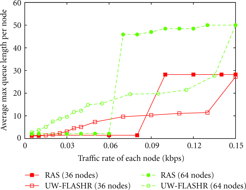
Queue length.
Furthermore, because small-scale networks are less likely to suffer congestion, the queue length of 36-node RAS networks soars at about traffic rate 0.09 kbps rather than at 0.07 kbps. It stabilizes at around 27 rather than at 50 when the traffic rate is larger than 0.11 kbps. Eventually, it will stabilize at 50 when the traffic rate is very high. Nevertheless, 0.15 kbps is not a very high traffic rate for 36-node networks, thus only a majority of the nodes are congested while the others sustain empty queue. Still the queue length of RAS networks is much larger than that of UW-FLASHR networks when congestion happens in RAS networks, which again indicates that the queue utilization of RAS networks is fairer and higher.
In summary, greater maximum queue length allows fairer and higher utilization of the queue. Correspondingly, the delay upper bound of the RAS networks is higher than the UW-FLASHR networks because more faraway packets are capable of arriving at the BS with no overflow in queue.
5.5. Retransmission Time of RRAS
In this subsection and the following subsections, each node generates 1 packet for the BS periodically. Experiments are performed to determine the actual length of the retransmission period. Although we compare UW-FLASHR with RAS, we cannot compare it with RRAS, because it does not contain retransmission mechanism. According to (6), the theoretical length of the retransmission period is conservatively long, attempting to fit in all possible retransmission communications. Actually, the retransmission time can be much shorter. In Figure 8, RRAS(1) and RRAS(2) are the retransmission time when the retry time is 1 and 2 respectively. Theoretical RRAS(1) is the retransmission time calculated with (5) when the retry time is 1.

Retransmission time.
In Figure 8, with loss rate (loss is caused by the wireless environment) increasing from 0, the retransmission time of all the three cases increases from 0. RRAS(2) is about a double of RRAS(1), because it retransmits the lost packet one more time. When the loss rate is very low, say 0.04, RRAS(1) and RRAS(2) are equal, because the DATA packets that need retransmission are so few that they can be sent simultaneously. Theoretical RRAS(1) is the longest, because it is an overestimated value that attempts to accommodate all possible retransmission cases. As a result, to save the time spent on retransmission, we can adjust the retransmission time according to the simulation results and the loss rate in the deployment.
5.6. Working Time of RRAS and RAS
Working time is the total time that a node is turned on. During the working time, the node can be sending, receiving, or idling, but not sleeping. For RAS, the working time is the schedule time, and the sensor nodes sleep for the rest of the cycle time. For RRAS, the working time is the schedule length plus the retransmission time. For the traditional CSMA/CA used in TWSNs, the working time is the time used for transmitting all DATA packets to the BS without exceeding the required retry times. Besides RAS, RRAS(1), RRAS(2), and theoretical RRAS(1), Figure 9 also shows the working time of CSMA/CA(1) and CSMA/CA(10), with 1 and 10 as the retry limit, respectively.
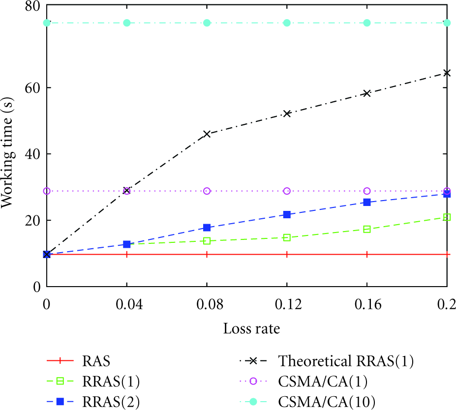
Working time.
Because the traditional CSMA/CA employs RTS/CTS handshaking and does not design the collision avoidance mechanism suitable for UWASNs, many packets are collided and its efficiency is very low. The CSMA/CA has to retransmit the collided DATA packets, and it cannot successfully retransmit all the collided DATA packets to the BS when the retry time limit is 10, let alone when the retry time is 1. As a result, no matter what the loss rate is, the working time of CSMA/CA is a constant. In other words, the protocol for UWASNs should first settle down the negative effects caused by improper collision avoidance methods of the traditional CSMA/CA, and then recovers the packet loss caused by the volatile environment. Figure 9 also demonstrates that (1) the RAS work time is the lower bound of all because it does not retransmit, and, (2), except for CSMA/CA, the working time increases with the increase of retry time and loss rate.
5.7. Success Rate of RRAS and RAS
The success rate is defined as the DATA packets received by the BS divided by the total DATA packets for the BS. Because the RAS does not perform ACK or retransmission mechanism, its DATA success rate is reduced by the loss rate. RRAS can achieve a higher success rate. Figure 10 verifies that compared with RAS, RRAS attains a higher success rate, especially when the loss rate is high. In addition, success rate of RRAS(2) is higher than that of RRAS(1), because RRAS(2) retries one more time. However, according to Figure 8 and Figure 9, one more retransmission of RRAS(2) results longer retransmission and working time. Finally, as discussed previously, the efficiency of CSMA/CA is very low, including the success rate.

DATA transmission success rate.
5.8. Throughput of RRAS and RAS
According to [1], the throughput is defined as a function of the sensor node working time and the total DATA packets received by the BS:

In consistency with the poor success rate, the traditional CSMA/CA efficiency is also very low in Figure 11. As discussed in subsection retransmission time, the throughput of the traditional CSMA/CA is determined by its poor collision avoidance method rather than by the packet loss rate caused by the environment hence, it is flat. According to Figure 11, the throughput of RAS is the highest, but the throughput performance of RRAS is not greatly reduced, especially when the loss rate is not very high. Since the success rate of RRAS is much higher than RAS according to Figure 10, we can observe that RRAS obtains a good tradeoff between the reliability and the throughput.
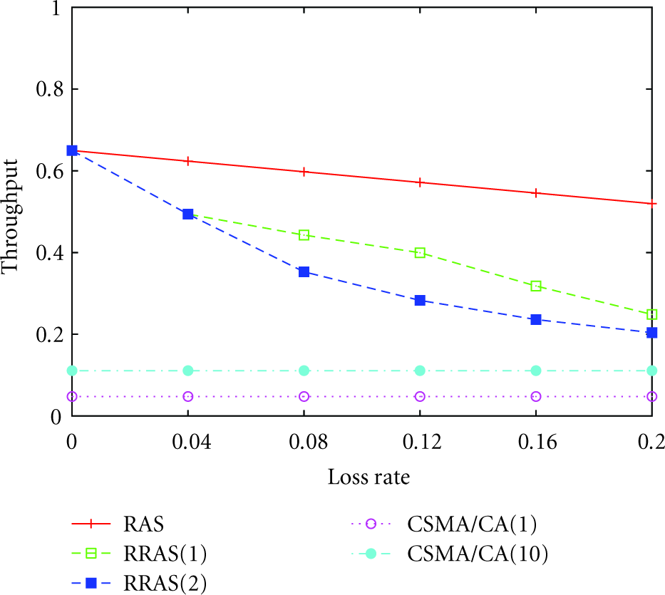
Throughput.
6. Conclusions
In this paper, we propose an efficient MAC protocol called RAS to improve the efficiency in UWASNs. Then RRAS, the reliable RAS, is implemented to achieve a tradeoff between the reliability and efficiency performance in UWASNs. RAS employs priority scheduling with coarse synchronization and information of the rough propagation delays between each node pair. With these condition and parallel transmissions, RAS can calculate a compact schedule at the BS when static routing is applied and the DATA direction is only from the sensor nodes to the BS. To improve the throughput, RRAS employs the RAS scheduling to transmit the majority of the DATA generated in a cycle to the BS. Then, it designs a NACK-retransmission mechanism to retransmit the DATA packets lost during the previous DATA transmissions. Because this new NACK-retransmission mechanism is based on the RAS scheduling that allows each node to know the packets it should receive during a cycle, it can trigger the NACK requirement after a node identifies its lost packets. Both the NACK and retransmission packet transmissions are distributed. They are based on ALOHA so as to reduce the control frame handshaking and improve throughput. The simulation results demonstrate that RAS is not only efficient, but also obtains good fairness performance. RRAS not only effectively improves the reliability through retransmission, but also attains a comparable throughput. In the future, we are interested in researching the performance of the current MAC protocols when the loss rate is higher than 20% and design a reliable protocol for such situation.
Footnotes
Acknowledgments
The work described in this paper was supported by a grant from the Research Grants Council of the Hong Kong Special Administrative Region, China (Project no. CUHK4154/10E) and sponsored in part by the National Basic Research Program of China (973) under Grant no. 2011CB302600.