
Abstract
Radio frequency (RF) tags have been widely used in inventory tracking, environmental monitoring, battlefield situational awareness, and combat identification due to their low cost, small size, and wireless functionality. This paper explores the application of active RF tags in outdoor environments responding to random noise radar interrogations with predetermined messages. A conceptual system design for communication between radar and RF tags using ultrawideband (UWB) noise waveforms is proposed and analyzed theoretically and via simulations. The tag structure comprises a sensing receiver and active receiver/transmitter. The sensing receiver senses the radar header consisting of a prearranged secret realization of the noise waveform. The active receiver/transmitter modulates the RF tag's message onto the radar interrogation signal through weighted tapped delays and reradiates the tag message back to the radar. System performance is evaluated in terms of symbol error probability in an additive white Gaussian noise (AWGN) channel. A technique to combat multipath interference is presented. It is shown that this system is capable of communicating a suite of messages from the tags to the radar.
1. Introduction and Background
RF tags, also known as radio frequency identification (RFID) tags, are small electronic devices typically adhering to objects of interest which can communicate with a tag interrogator through a wireless channel. They have the advantage of being read through a variety of visually and environmentally challenging conditions, such as building walls and foliage, where barcodes or other optically read technologies will not work [1, 2]. Their properties such as low cost, small size, and wireless functioning make them widely used in inventory tracking [3], object location [4], environmental monitoring [5], environmental management [6], personnel identification [7], and so forth. RF tags are also good candidate technologies for combat identification (CID), which provide the necessary awareness to identify friendly combat entities and avoid fratricide [8]. An RF tag can also operate as a data carrier, where information can be written to the tag. Radar-responsive tags have both military applications, such as battlefield situational awareness, combat identification, targeting, personnel recovery, and unattended ground sensing, as well as government applications, such as nonproliferation, counter-drug, search-and-rescue, and land mapping [9]. There are three types of RF tags based on the characteristics of the power source: passive, semipassive, and active. Passive tags use the energy from the incoming signal to power themselves and have practical read distances from about 10 cm up to a few meters. Semipassive and active tags require an internal power source, usually a small battery, and thus have longer operating distances up to hundreds of meters [10].
Using the reflected power for communications, dating back to the late 1940s, was an insightful exploitation of radar systems for multifunctional usage [11]. In [12], an electronic identification system which uses modulated backscatter from an RF beam-powered tag is described, where the reader transmits a single frequency RF signal, and a subcarrier is used in the return signal format for achieving clutter suppression. A controllable radar reflector consisting of an array of resonant dipoles or slots combined with a reflecting plate was used to establish passive telemetry system for transferring information from the site of a target to a radar station [13]. Backscatter modulation is a suitable modulation scheme for tagging because no RF source is needed for the remote devices. Such a tagging system has been proposed wherein frequency hopping combined with backscatter modulation is used for interrogating the tag [14].
A programmable covert radio tag able to communicate with a variety of RF pseudorandom modulated waveforms emitted from a source of interrogating energy was developed so that military troops wearing the RF tag could operate undetected [15]. A scheme to embed the communication signal within the radar backscatter using a tag/transponder on an intrapulse basis is proposed in [16]. Their approach is based upon eigen-decomposition of the collection of delay shifts of the incident radar waveform. Another scheme to ensure covertness is through the use of noisy tags, which are regular RFID tags that generate noise. These have been used to establish secret keys on-the-fly between the reader and the tag, so that an eavesdropper would only hear the noise, but the intelligent receiver could subtract the noise and recover the intended signal [17]. A technique to identify multiple tags simultaneously by weighting and combining the in-phase (I) and quadrature (Q) channel signals was implemented in [18]. The concept of orthogonal frequency coding (OFC) offers enhanced processing gain, lower interrogation power spectral density (PSD), and the possibility of adding pseudo-noise coding for covertness [19].
A general mathematical formulation of the intrapulse radar-embedded communication in the ambient radar scatter interference is provided in [20]. Linear frequency modulated (LFM) waveforms are also candidates for radar communications, which use signal processing rather than hardware to mitigate the interference problem [21]. Chirp waveforms are used in [22], wherein a multifunctional UWB communication and radar system has been designed and implemented. Other aspects of relevance to the radar communication system, such as the candidate radar types and sharing of resources. are discussed in [23]. As part of the Department of Defense Future Combat System (FCS) philosophy, each element of a network-centric force, for example, a radar sensor and an unmanned aerial vehicle (UAV), is expected to possess an embedded communications capability [24].
While narrow band noise radars have been proposed and refined over the past fifty years [25–31], the concept of UWB random noise radar has seen significant development more recently [32–37]. In contrast to conventional radar, the UWB noise radar transmits a noise or noise-like waveform having a fractional bandwidth of greater than 25%. The return from the target is cross-correlated with a time-delayed replica of the transmit waveform to determine the range to the target with a range resolution inversely proportional to the bandwidth. Noise radars satisfy important requirements for military systems, such as low probability of interception (LPI) and low probability of detection (LPD), owing to the featureless characteristics of its waveform [38]. Moreover, the aperiodicity of the waveform also causes the suppressed ambiguity in range/velocity [39]. Another advantage of UWB noise radars is their ability to efficiently share the frequency spectrum. A number of UWB noise radars can operate over the same frequency band with minimal cross-interference since each noise waveform is uncorrelated with the others.
In this paper, we propose a conceptual design of an RF tag responding system to assist a noise radar in collecting relevant information on slowly-moving assets and tracking their whereabouts in an outdoor environment, inspired by the results of recent research [40, 41]. In our scenario, the radar sends out interrogation signals to gather the assets' conditions and RF tags associated with assets in the field respond to the radar with appropriate messages. The proposed RF tag is able to send various kinds of messages from its associated asset. The maximum number of messages the tag is capable of conveying is determined by the length of its delay line. Furthermore, the proposed RF tag responding system is able to operate covertly in the sense that its symbol error rate (SER) is still small under very low channel signal-to-noise ratio (SNR). In our approach, a UWB noise waveform is chosen as the probing signal owing to its low probability of detection and interception capabilities as well as its immunity from interference and jamming. The waveform is generated by amplifying and bandpass filtering the thermal noise generated by a resistor; thus, the waveform is not to be considered to be pseudo-noise, the latter being generated deterministically and therefore possessing a cyclic autocorrelation function. Since the UWB noise signal used as the information carrier is easy to generate, it simplifies the system implementation while achieving a fair amount of covertness. It may certainly be possible to detect a true thermally-generated noise signal embedded in ambient noise, but only if adequate time and processing resources are available, which is unlikely in the scenarios considered in this paper.
This paper is organized as follows. The system model is described in Section 2, where the design of the RF tag and radar detector is illustrated. In Section 3, we demonstrate the operation of the proposed system in an AWGN channel. The system performance is evaluated in terms of the SER. An algorithm to reduce the interferences from multipath signals on the RF tag-to-radar link is presented in Section 4. Conclusions are presented in Section 5.
2. System Model
2.1. RF Tag Structure
The transmitted UWB noise radar signal has the form as shown in Figure 1, which is composed of two parts

Radar transmitted signal: (a) signal format and (b) time (top) and frequency (bottom) domain representations.
The header of radar transmitted signal can be randomly selected from a suite of preassigned random headers to better protect it from detection by undesired parties. However, this increases the complexity of RFID tag's architecture and RFID tag's energy consumption during the detection of radar header. This is because the RFID tag in the system needs to store the entire suite of radar headers beforehand and correlate its received signal with each stored radar header to determine whether the incoming signal is from the radar. Furthermore, the RFID tag in our system is battery powered for longer range and advanced functionalities, and its energy consumption is also of concern in the system design. Instead, we propose that the radar header remain the same random waveform for each radar interrogation. Since this single radar header signal used in our system has randomness features, it is relatively difficult to be detected.
The RF tag functional block diagram is shown in Figure 2. It consists of two parts: a sensing receiver and an active receiver/transmitter. The sensing receiver is merely a listening device which uses moderate amounts of power and is used to sense the radar header. The active receiver/transmitter is turned on once it gets an indication signal from the sensing receiver output that the radar header is detected. Upon receiving this wake-up call, it begins to receive and process the rest of the incoming signal, embeds the appropriate RF tag message, and retransmits the message bearing RF tag signal back to the radar.

RF tag functional block diagram.
The RF tag operates in two modes: working mode and sleep mode. In the working mode, once the sensing receiver detects the radar header and sends a control signal to the active receiver/transmitter to turn on, the sensing receiver turns off. The active receiver/transmitter also turns off after completing the delay-modulation of the radar inquiry signal. Thus the entire RF tag goes into the sleep mode after it is triggered. It will stay in the sleep mode for a period which is longer than the maximum multipath delay. Then the sensing receiver turns on again, waiting for the next radar header to arrive. Now the entire RF tag is in the working mode again. This way, the RF tag will not be triggered by the multipath signals in the radar to tag link, and it will not miss the radar's inquiry. Besides, the RF tag is not always in working mode, and thereby improving its energy efficiency.
The sensing receiver functional block diagram is depicted in Figure 3. The bandpass-filtered received signal is cross-correlated with a replica of the radar header, which is saved at the RF tag a priori. The output of the correlator goes through a threshold detector whose output controls the RF tag's active receiver/transmitter. If the output of the correlator exceeds the threshold at some observing time, then the active transmitter/receiver is turned on.
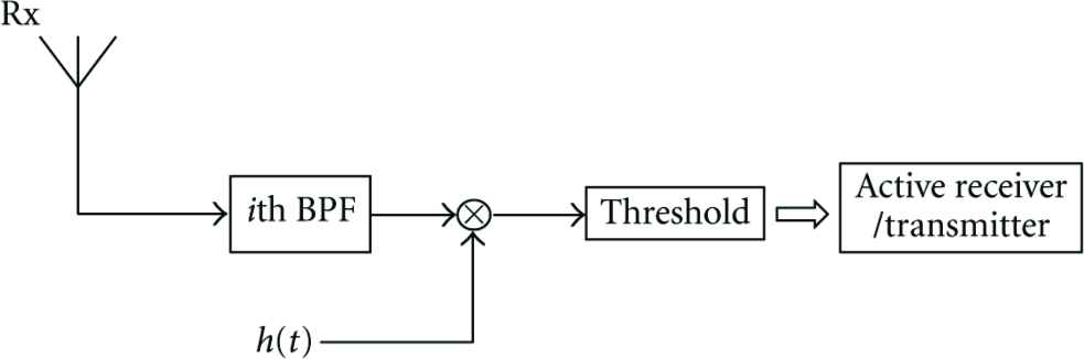
RF tag sensing receiver block diagram.
The RF tag active receiver/transmitter functional block diagram is shown in Figure 4. If and only if the radar wake-up signal is detected by the RF tag passive receiver, then the RF tag active receiver/transmitter is enabled. The remaining portion of the radar signal, namely, the radar information bearing signal

RF tag active receiver/transmitter architecture.
The entire bandwidth of the radar signal is divided into several subbands without mutual overlap by the RF tags, all of the same bandwidth

Frequency band allocation for RF tags.
If the number of RFID tags in the radar's range is not fixed, the radar interrogation signal's frequency band can be divided into
Next, one branch of the bandpass filter output
The other branch of the bandpass filter output, which is used as the indicator of RF tag message's arrival, goes directly to the amplifier and is retransmitted to the radar. Following this signal is the output of the weighted tapped delay line, which also goes through the amplifier and is transmitted back to the radar. Thus, the retransmitted signal for the ith RF tag has the vector form
2.2. Radar Detector Structure
The radar detector functional block diagram is depicted in Figure 6. To detect the ith RF tag's message, the radar received signal

Radar detector block architecture.
Correlator 2 is used to decode the RF tag's message. Compared to Correlator 1, Correlator 2 has a longer integration time, denoted by
Delay
Figure 7 illustrates the structure of the correlator. The received signal is mixed with a time delayed version of the filtered transmitted signal

Structure of correlator.
When there are multiple RF tags to be interrogated by the radar, several above detectors can be connected at the radar receiver in parallel, with each bandpass filter tuned to the corresponding RF tag's center frequency.
3. System Operation and Performance Analysis
We consider AWGN and propagation delays introduced by the channel. The internal thermal noise at the RF tag and radar is neglected since it is much lower than the channel noise. We consider the link between the radar and RF Tag 1 as an example to show the operation of the proposed system.
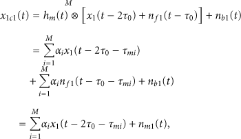
As stated before, to interrogate the RF tags, the radar transmits the header
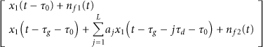
Tag 1 thus transmits the signal
At the radar receiver, the received signal after the bandpass filter
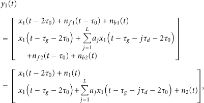
The signals transmitted by other tags occupy different frequency bands, which do not overlap with the frequency band of the signal transmitted by the tag under consideration; thus the signals transmitted by other tags are uncorrelated with the desired signal. Therefore, the interference signals transmitted by other tags simply raise the noise floor at the radar detector corresponding to the tag under consideration. Furthermore, the guard band between individual tag frequency bands is designed to be much larger than the maximum Doppler frequency shift. The effect of such interferences on the system performance is equivalent that of a degraded channel SNR.
The output of Correlator 1 is derived as

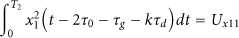
Similarly, the output of Correlator 2 is given by

To retrieve the RF tag message, we need to observe the magnitude of the output of Correlator 2 at time lags
To demonstrate on paper the operation of the RF tag responding system, we ran simulations on the following example.
A 4th-order bandpass Chebyshev filter with 0.5 dB ripple in the passband is used for the simulation, whose frequency response is shown in Figure 8. The radar transmits a 1-2 GHz noise signal to the RF tags. The ratio of the durations of the radar header to the radar inquiry signal part is 1 : 5. To illustrate the operation of the proposed system, suppose that there are three RF tags within the radar's range. The RF tags operating bandwidth is 320 MHz and their frequency band allocation is as follows: Tag 1 occupies 1–1.32 GHz, Tag 2 occupies 1.34–1.66 GHz, and Tag 3 occupies 1.68–2 GHz. The guard bandwidth is 20 MHz, which is much greater than what is needed to account for the tag's maximum possible Doppler shift. The channel SNR is −3 dB, and the channel round propagation delay is

Frequency response of bandpass filter at the radar transmitter output.
Figure 9 shows the simulation results of RF Tag 1's message decoding in the AWGN channel case in the example system. The output of Correlator 1 has a peak at the time lag of

Example system RF tag message decoding in AWGN channel at an SNR value of −3 dB. The right plots are zoomed in at the peaks of the left plots.
The performance of the system is evaluated in term of the symbol error probability, also known as the symbol error ratio (SER) [42]. As stated above, interferences such as clutter reflections and other RF tags' transmitted signals can be either discriminated from the desired signals at the radar decoder or can be analyzed as being equivalent to a worse channel SNR. In the following analysis, we derive the SER of our system in an AWGN channel to give a theoretical bound that our system can best achieve. Whether the RF tag's message can be correctly decoded or not depends on the outputs of both the Correlator 1 and Correlator 2. The RF tag header has to be detected at first.
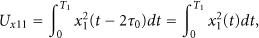
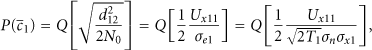
The output of Correlator 1 gives an indication whether this RF tag responds to the radar. As stated in Section 2, the zeroth bit of the RF tag's message (when it exists) is always 1, and since
The RF tag message decoding rule is that if no peak of Correlator 1's output appears at any time, then the RF tag's message is wrongly decoded; else if the peak of Correlator 1's output appears at some time
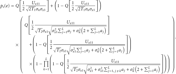
Therefore, the symbol error probability can be written as

The probability


Since

The signal component of

If Correlator 1 at the radar receiver correctly detects the existence of the RF tag signal, we need to check whether the 0th bit of RF tag's message exists or not. The output of Correlator 2 at the corresponding time is given by


Since

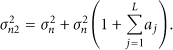
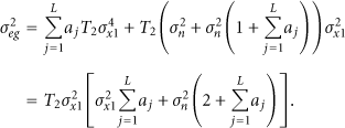


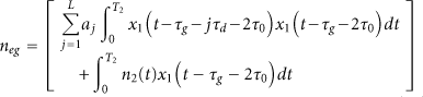
The signal component of

The average probability of error for the kth bit of the RF tag's message is given by

As can be seen from (14) and (21), when the RF tag transmits all 1-bit message, the noise floor is higher than when it transmits other kinds of messages. Thus, the worst SER is obtained for this case.
We ran simulations on the proposed system's SER using the same example system as that for system operation illustration. The RF tag has a 3-tapped delay line, where the delay between adjacent taps is 90 time lags, and the delay before the tapped delay line at the RF tag is 5030 time lags. The round propagation delay is 16000 time lags. Radar transmits a 1-2 GHz noise signal towards the RF tag, and the RF tag signal occupies the 1−1.32 GHz band. In Figure 10, simulation results of the SER are shown as a function of the channel signal-to-noise ratio (SNR), and it is compared to the theoretical result derived from (25). We note from Figure 10 that the simulation and theoretical results agree to within 0.5 dB. The simulation and theoretical results show that the proposed system is capable of covertly and securely communicating messages even under negative channel SNR conditions with tolerable symbol error probability. When the channel SNR is −2 dB, the SER of the system is at the 10−3 level, and the system still performs well at −4 dB channel SNR, where the SER is at the 10−2 level. Figure 10 also reveals that the theoretical curve slightly overestimates the SER at a given channel SNR compared to the simulation results, but the agreement is within 0.7 dB over the range investigated. The simulated and theoretically derived SER curves do not match exactly due to the fact that in our SER derivation, we approximate the distribution of the noise term out of the correlator as Gaussian to obtain a closed form solution. However, since this noise term also contains products of Gaussian random variables, it is not strictly Gaussian distributed, according to [44].

Example system SER versus channel SNR for a 3-tap delay line at the RF tag.
4. Multipath Signal Reduction
The basic idea is that the signal from the branch directly out of the bandpass filter at the RF tag can also be used to sense the multipath channel on the RF tag-to-radar link during the detection by the radar when determining whether the corresponding RF tag is responding. The multipath channel information thus estimated is applied to the following sequence of signals to reduce the interferences brought about by the multipath signals, and to better decode the RF tag's message by the radar. Our simulation results show that this algorithm works for the proposed system. This algorithm is specifically designed for our system wherein we use random noise signal as the information carrier. We developed this algorithm considering both the complexity of the system, especially the simple architecture of the RF tag, and the fact that the system can work in real time, as long as assuming the multipath channel remains relatively constant over the duration of tag operation.
IEEE 802.15.4a has provided channel models describing signal propagation over 3.1–10.6 GHz for various environments, such as indoor residential, indoor office, industrial environments, and so forth. The set of IEEE multipath channel models is based on the Saleh-Valenzuela model, where the paths arrive at the receiver in clusters. To demonstrate how our proposed scheme combats multipath signal interference, we use a more simplified channel model.
Consider the RF tag-to-radar link. The multipath channel response is simply modeled by a finite set of delay and attenuation pairs

The radar received signal out of the bandpass filter which flows to Correlator 1 is given by
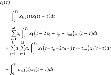
Similarly, the branch of the radar bandpass filter to Correlator 2 is given by

The output of Correlator 1 is calculated as

The first step of tag message decoding is to suppress the noise floor of

The next step is to apply the information obtained from
Step 1.
Intercept the part of
Step 2.
Check the 0th bit of the RF tag's message by observing the magnitude of
Step 3.
Intercept the part of
Step 4.
Intercept the part of
Step 5.
Repeat the above operation on the resulting signal iteratively at time lag
The following is a simulation validation for this method. We use the same system example as that in Section 3, except that channel is changed. The channel impulse response used in the simulation is shown in Figure 11, which, although not a standard one, is used just for algorithm testing and validation purposes. The wavelet used in the test is the Daubechies-4 (db4) wavelet. The simulation results are shown in Figures 12(a)–12(h). Figures 12(a) and 12(b) show the correlator outputs wherein the multipath signals and significant amount of noise are shown. The correlator outputs after denoising as per the procedure outlined in (31) are shown in Figures 12(c) and 12(d), wherein we note that noise has significantly reduced. Figure 12(e) shows the output of Correlator 2 after the first multipath signal removal. An enlarged view of the Correlator 2's output after the first multipath signal removal is presented in Figure 12(f), which shows a high peak value at around 90 lags, which equals

Channel impulse response used for testing.

Example system multipath channel results. (a) Correlator 1 output in multipath channel case, (b) Correlator 2 output in multipath channel case, (c) Correlator 1 output after noise suppression, (d) Correlator 2 output after noise suppression, (e) RF tag message decoding after the 1st multipath signal removal iteration, (f) same as (e) with lag scale expanded, (g) RF tag message decoding after the 2nd multipath signal removal iteration, (h) RF tag message after the 3rd multipath signal removal iteration.
In the multipath channel, there will also be multipath from the radar to the RF tag. The radar-to-RF tag channel and the RF tag-to-radar channel are likely to be different given that both systems will have different antenna patterns. As stated in Section 2.1, our design of the sleep mode in the RF tag's operation assures that during one radar inquiry, once the RF is triggered, it will not be triggered by multipath signals.
5. Conclusions
This paper explores the application of active RF tags, affixed on friendly assets, operating in outdoor environments and responding to random noise radar interrogations with predetermined messages. A conceptual system design for communication between the tags and the radar using UWB noise waveforms is proposed and analyzed. The use of noise waveforms generally maintains covertness and immunity from interference, especially in electromagnetically dense applications. In the proposed design of the system, the RF tag functional block comprises two parts: the sensing receiver and the active receiver/transmitter considering the efficiency of energy consumption. The sensing receiver is designed to sense the radar header, which is a prearranged secret realization of the noise waveform for the purpose of covertness. The active receiver/transmitter modulates the RF tag's message onto the signal through weighted tapped delays considering the simplicity of the RF tag structure. The RF tag's ID is embedded through the frequency band of its transmitted signal. The operation of the system is demonstrated and the performance of the system is analyzed in an AWGN channel. A mechanism to combat the interferences caused by multipath signals is presented for the proposed system in the multipath channel case. In the example considered for the system design demonstration above, where the RF tag has a 3-tapped delay line, simulation results show that the RF tags are able to respond to the radar with various kinds of messages. The symbol error probability of the system in the example is at the 10−3 level when the channel SNR is as low as −2 dB, and it still performs well when the channel SNR is −4 dB. Since tag message detection is accomplished via cross-correlation with constantly varying transmit replicas known only to the radar that generates the noise waveform, the radar transmit signal can be maintained smaller and well-concealed within the ambient RF noise.
Possible future work for this proposed system includes the hardware implementation and testing over-the-air. Various mature technologies, for example, microwave, photonic, and acousto-optic, can be implemented to realize the switchable delay lines at the RF tag for transmitting different messages, as described in [50–54]. Compact wideband antennas suitable for RFID tags are discussed in many recent papers. In [55], a low-cost, wideband planar antenna for RFID tags mountable on metallic surfaces covering 57 MHz bandwidth at a 3-dB return loss has been presented. A wideband antenna for RFID tag that can process 1-2 GHz is also realizable. A UWB antenna operating over 300–2700 MHz with a size less than 15 cm square is reported in [56], while one operating over 400–800 MHz with a size of approximately 10 cm square is reported in [57]. Thus, we believe that suitable antennas are available for use with our proposed RF tag implementation.
Although noise waveforms are discussed and developed in this paper, constant envelope (CE) noise-like waveforms, such as clipped noise, chaos, code division multiple access (CDMA), and orthogonal frequency division multiplex (OFDM) waveforms, can also be used. While these may not possess as good LPI or LPD characteristics as pure noise waveforms, they are able to use power amplifiers in the saturated mode using as little DC power as possible.
Footnotes
Acknowledgments
The authors appreciate valuable comments and suggestions received from Dr. Jon Sjogren of the US Air Force Office of Scientific Research (AFOSR). This work is supported by the US Air Force Office of Scientific Research (AFOSR) Grant no. FA955006-1-0029.