
Abstract
This paper presents the analysis of static bending of beams made of functionally graded piezoelectric materials (FGPMs) under a combined thermo-electro-mechanical load. The Euler Bernoulli theory (EBT), first-order shear deformation theory (FSDT) and third-order shear deformation theory (TSDT) were employed to compare the accuracy and the reliability of each theory in applications. The material properties vary continuously through the thickness direction. The material compositions were selected from the PZT family. The governing equations were derived from Hamilton's principle and solved using the finite element method and Fourier series method. Cubic Hermit interpolation shape function was used for estimating the transverse deflection, and the linear interpolation function was used for the axial displacement and the shear rotation as well. Fourier series expansion, based on the boundary conditions, were employed to solve the governing equations analytically. The accuracy of the method was validated by comparing the results with the previous studies. Finite element results were compared with the analytical results presented in this paper. A comprehensive parametric study is conducted to show the influence of the voltage, shear deformation, material composition, end supports, and the slenderness ratio on the thermo-electro-mechanical characteristic.
1. Introduction
The concept of the well-known functionally graded materials (FGMs) was extended to a piezoelectric material to improve its reliability and performance, and a new kind of material, such as a functionally graded piezoelectric material (FGPM), was developed [1]. Monomorph and bimorph piezoelectric actuators are used for applications which require large displacement output. Since these actuators are manufactured by bonding one or two piezoelectric layers to a metal shim layer, the bonding interface has low strength. On the other hand, large stress discontinuity and concentration are initiated in the bonding interface due to the difference of material properties between the shim and piezoelectric layer [2]. To solve this problem, a novel class of actuators were developed in 1995 in which one or more layers were made from FGPMs with thermo-electromechanical properties varying smoothly along the layer thickness [3]. The FGPMs are designed to withstand against high thermal disturbances specially in the cases with shock nature, and it has been proven, both theoretically and experimentally, that the durability, reliability, and actuation performance of actuators can be greatly improved by the use of FGPMs. A number of fabrication techniques for the FGPM structures have been proposed and successfully implemented [2, 4–8].
Many structural systems are routinely modelled as beams. Hence, the static behavior of rectangular FGPM beams in terms of the transverse deflection, transverse shear strain, and stresses may be examined. The design and analysis of these types of smart structures may require the use of the finite element method. Detailed reviews of the finite element (FE) modelling for adaptive structural elements consisting of piezoelectric hybrid plates have been reported by Benjeddou [9] and Mackerle [10]. Based on the layerwise theory, Saravanos et al. [11] applied a numerical investigation for the dynamic behavior of piezoelectric laminates. Kapuria and Alam [12] used a finite element model for dynamic analysis of hybrid piezoelectric beams based on the zigzag theory. Heiliger and Reddy [13] presented the bending and vibration problems for FGM structures based on the TSDT. In another study, Fernandes and Pouget [14] proposed a new approach for governing the equations of the laminated plates with piezoelectric layers by expressing the electric potential as a function of the thickness coordinate. The shear correction factor of elastic displacements was considered in their study. The modelling and optimal design method for the piezoelectric microactuators was developed by DeVoe and Pisano [15]. They assumed that the piezoelectric coefficient varies linearly along the thickness direction and other material parameters assumed to be constant. Hauke et al. [16] performed an experimental study, and they showed that, compared to the homogenous beam, the deflection of an FGPM beam is only slightly smaller when beam is long; on the other hand, the internal mechanical stress is drastically reduced. Due to these advanced properties, the mechanical stresses in beams with FGPM sensors and actuators are significantly decreased [17]. Closed-form solutions for the FGPM cantilevers with a linear gradient for the mass density and with a linear gradient for the piezoelectric constant e31 were performed by Zhifei and Shi [18, 19]. He used the two-dimensional theory of elasticity to develop the governing equations and employed the Airy stress function to solve them. Based on the EBT, Kruusing [20] presented an analytical solution to calculate the tip deflection and the blocking force of a cantilever actuator with a graded elastic constant when the actuator was subjected to a transverse point load at the tip. Joshi et al. [21, 22] obtained exact solution for the electrically induced bending [21] and thermoelectric bending [22] of a laminated beam consisted of an FGPM layer and an active piezoelectric layer. Yang and Xiang [23] employed generalized differential quadrature (GDQ) method to solve the governing equations of the FGPM beam, and they validate the accuracy of GDQ method comparing to the other numerical methods.
The literature survey gives a clear indication that studies on the static deflection and stresses under ambient loading conditions of FGPM beams, using the TSDT, have been rarely reported in the literature. In the present paper, the principle of stationary potential energy is used to obtain the static finite element equilibrium equations of the FGPM beams with uniformly distributed mechanical, electrical, and thermal loads. The finite element formulation follows the conventional displacement-based approach employed to derive the stiffness and force matrices. In addition, another approach to obtain the governing equations of the FGPM beam based on the EBT is used in the paper. The Fourier series expansion is employed to solve the equations analytically.
2. Material Properties
Figure 1 shows the configuration of FGPM beam made of PZT-4 and PZT-5 with the length L, width b, and thickness h. The material properties vary continuously along the z-direction. Top surface consisted of pure PZT-4, and the bottom surface is composed of pure PZT-5. Different mathematical models are developed to simulate the distribution of the material constituent in the FGMs [24–26]. One frequently used model for the FGMs is the power law model proposed by Reddy [26], which has the privilege of leading to simplified equations to be solved for analytical solutions. In this formulation, the volume fraction of material composition are assumed to obey the power law distribution with the simple law of constituent mixture as

where P e is the effective material property of the FGPM beam, P t is top surface (PZT-4) property, and P b is the bottom surface (PZT-5) property. In this paper, z=+h/2 leads to P e = P t that denotes that the top surface of the FGPM beam consists of PZT-4 and z=-h/2 leads P e = P b which means that, at the bottom surface of the FGPM beam, PZT-5 is the only material constituent. In the power law formulation, n is the volume fraction index of FGPM beam. For n=0, we have P e = P t , and for n=∞, we have P e = P b . The two cases correspond to the isotropic PZT-4 and PZT-5, respectively. The material constants are presented in Table 1.
Material properties of FGPM constituent.


The geometry of the FGPM beam and the possible variation of material constituent through the thickness.
3. Governing Equations
3.1. Finite Element Method
The geometry of deformation for a beam based on different beam theories is presented in Figure 2. The rotation,

where c0 = −4h2/3. Subscript comma denotes the differentiation, u0 is the midplane axial displacement, and w0 is the midplane transverse deflection. This displacement field accounts for traction-free condition on the top and bottom surfaces of the beam. A Cartesian coordinate system (x,z) is introduced in the present analysis. We consider an FGPM beam with length L and depth h, as shown in Figure 1. The beam is polarized in z-direction and has a graded profile in this direction. The potential field is approximated linearly through the thickness, as given by
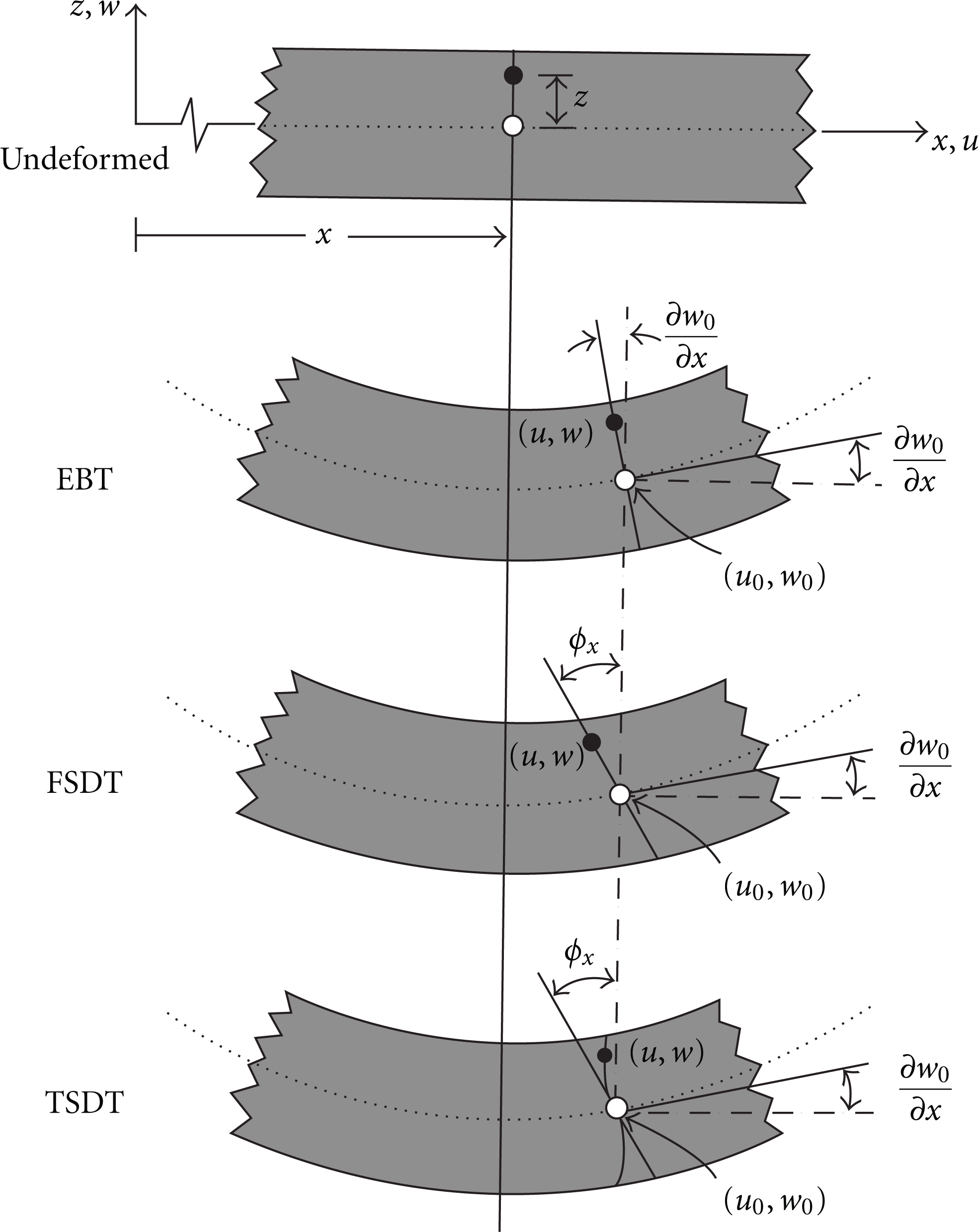
Kinematics of deformation of a beam in various beam theories.
Let ϵ i j ,σ i j ,D i and E i denote the strain tensor, stress tensor, dielectric displacement, and the induced electric field, respectively. The constitutive equations for a piezoelectric beam can be written as [27]

in which β is defined by

and C i j ,e i j ,P i ,α as well as ∊ i j are the components of the effective elastic, piezoelectric, pyroelectric, thermal expansion, and dielectric constants of the piezoelectric material, respectively. The straindisplacement and the electric field potential relations are

With these assumptions, the governing equations can be derived using Hamilton's principle as
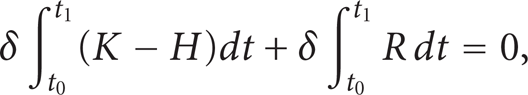
where the variation of electric enthalpy density δH, the variation of kinetic energy δK, and the virtual work δR due to the mechanical load q(X,t) are

Here, f b i ,f c i ,f s i ,q e and q t represent the body forces, concentrated loads, the specified traction, electrical surface charge, and heat flux, respectively. Using (4) and substituting (8) into the Hamilton principle (7) and integrating over the beam thickness gives

The degrees of freedom of the base element (e) are


The elements of the mass matrix [M u u ], membrane stiffness matrix [K u u ], the bending stiffness matrix [K u ϕ ], the piezoelectric stiffness matrices [K ϕ ϕ ], and the force matrices [F u θ ],[F ϕ θ ],[F q e ],[F m ] are

When electric load is applied, (11) is omitted and

In the present analysis, thermal load is considered as well. Constant surface temperature is imposed at the top and bottom surfaces. The variation in temperature is assumed to occur along the thickness direction only. Thus, the steady-state heat transfer equation is reduced to the one-dimensional equation as

with the boundary conditions such that T=T t at z=h/2 and T=T b at z=-h/2. Here, T is the temperature; T t and T b are the applied temperatures on the upper and lower surfaces, respectively. Term K is the thermal conductivity that may be assumed to follow the power law form, indicated by (1). The temperature field through the thickness of the beam is obtained by solving (14).
3.2. Fourier Series Solution
Consider an FGPM beam as shown in Figure 1. The material properties change gradually between the upper and lower surfaces according to (1). In the absence of the thermal load and temperature change, the constitutive equations for the stresses and the electric displacements for the steady-stated FGPM beam based on the EBT reduce to

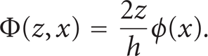
For mathematical simplification, the potential Φ(z,x) is assumed linearly across the FGPM beam thickness as [28]

in which ϕ+ and ϕ− are the electric potentials on the upper and lower surfaces of the FGPM beam, respectively. For the static analysis of the beam, the virtual work done by the electromechanical internal forces in the FGPM beam is

Using (15) and the electric field relation of (16), and substituting into (17) and using the virtual work by carrying the variation formulation, the governing equations are obtained as

where

where C11t and e31t are Young's modulus and piezoelectric constant of the upper surface of the FGPM beam, respectively. The sign (−) indicates dimensionless value. Using the dimensionless parameters, the governing (18) is given as

where

Considering the assumed boundary conditions, to solve the system of (20), a finite Fourier transformation can be used as

Formulas for the inverse of transformation are obtained by using relationship from the theory of Fourier series. To obtain the mth Fourier components of unknown variables, the system of (20) must be solved based on the choice of m.
4. Results and Discussion
Consider an FGPM beam with top surface made of monomorph PZT-4 and the bottom surface of PZT-5. The dimensionless deflection is defined as w0/h.
The present analysis is validated in Table 2 and Figure 3 through comparisons with the existing solutions available in the literatures. The tip deflection of a standard cantilever monomorph beam with different slenderness ratios L/h and different volume fraction indices is presented by Yang and Xiang [23], in order to gain an insight into the effect of transverse shear deformation. Figure 3 shows the dimensionless w0/h tip deflection of an FGPM cantilever monomorph actuator with L/h=6 and different values of volume fraction indices (n), that is subjected to a uniform pressure q=10 kN/m2 and an applied voltage V=20 V. The tip deflection is increased significantly as the volume fraction index changed from 0→1.75 and then tends to remain constant in the EBT but decreased regularly in the TSDT and FSDT. The relative difference between the TSDT and EBT solutions remained around 2.7–3.0% as the volume fraction index (n) changes from 0→10.
Dimensionless tip deflections of the cantilever FGPM beam under electromechanical load (n=0.2).


Tip deflection of the FGPM cantilever monomorph with a varying volume fraction index (L/h=6).
Table 2 presents the dimensionless tip deflection of an FGPM cantilever monomorph beam (n=0.2) with different values of L/h under a uniform pressure q=10 kN/m2 and an applied voltage V=20 V. The deflection of beams with three different theories (TSDT, FSDT, and EBT) is listed for direct comparison. The relative difference between the TSDT and EBT solutions, which is defined as [(TSDT − EBT)/TSDT]×100% to show the effect of shear deformation is not negligible for L/h┼6 (thick beam), indicating that the TSDT beam theory is more accurate in this case. For the slender actuators with L/h>6 this difference is less than 1% and decreased as the value of L/h is increased.
Figures 4 and 5 compare the tip deflections of the FGPM beams (L/h=6) with different volume fraction indices when subjected to a uniform pressure q=10 kN/m2 or an applied voltage V=100 V, using the FSDT and TSDT. The results are in good agreement with those reported by Yang and Xiang [23], where GDQ method is used for solving the governed equations. When only an external voltage is applied, the electrically induced bending deformation is primarily dependent upon the piezoelectric coefficient e31 and the applied electric load. So, increasing the volume fraction index (n) leads to fully reached PZT-5 beam with higher value of e31 and consequently less deflection.

The effect of the volume fraction index on the tip deflection of FGPM beam under mechanical load.

The effect of the volume fraction index on the tip deflection of FGPM beam under electrical load.
The accuracy of TSDT, FSDT, and EBT was investigated using the PZT4-PZT5 FGPM beam with different slenderness ratios under electromechanical load. Since the EBT dose not account for the effect of the shear deformation, this theory predicted less deflection compared with the FSDT, and TSDT. By increasing the proportion of L/h (slender beams), the effect of the shear deflection is reduced and the results of the TSDT, FSDT and EBT converge together. Figure 6 depicts the transverse deflection of the clamped-clamped beam subjected to electrical load V=10 V. As expected, for the thick beams (e.g., L/h=4), the EBT estimated inaccurate deflection. When the magnitude of L/h is approaching to 20, the effect of transverse shear became negligible, and it may be seen that for L/h=20, the difference of the midpoint deflection of the beam estimated by EBT and TSDT is less than 2%.

The effect of the slenderness ratio L/h on the deflection of clamped-clamped FGPM beam under electrical load (V=100 V).
A simply supported FGPM beam with the slenderness ratio L/h=6 and L=0.025 m subjected to uniform mechanical load q=10 kN/m2 on the top surface is considered to compare the results of Fourier series solution with the finite element solution based on the EBT. Figure 7 presents the electric field E z at the middle point, across the thickness direction of the FGPM beam, caused by mechanical load obtained from the Fourier series and finite element solution. Based on Figure 7, increasing the volume fraction index (n) in the range 0≤n≤2 leads to the growth of the electric field, and after that the electric field starts to decrease for higher values of n. The reason is the difference between two coefficients e31 and ∊33 for the PZT-4 and PZT-5. Comparing the curves in Figure 7, it is clear that, for 0≤n≤2 (rich PZT-4 in material composition), Fourier series solution and finite element solution coincide properly, but, for n≥2 (increasing the PZT-5 portion in material composition), the results based on the Fourier series solution show higher value of the electric field. Although in both solutions the electric field is assumed to vary linearly through the thickness, but the finite element solution based on the EBT leads to inaccurate results compared to the Fourier series solution. It is predicted that the reason is mainly due to using the approximated shape functions in the finite element solution.
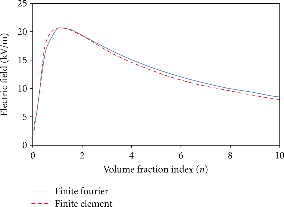
Comparison of the electric field versus volume fraction indices at the middle of simply supported FGPM beam under mechanical load obtained from Fourier series and finite element solution. (L/h=6,q=10 kN/m2).
Behavior of the simply supported FGPM beam under thermal loading is investigated using the EBT and TSDT. In the present analysis, constant surface temperature is imposed at the top and bottom surfaces as the thermal load.
The temperature of the top PZT-4 rich surface is fixed at 400°K and that of bottom PZT-5 -rich surface is kept constant at 350°K. It is assumed that the reference temperature is T0 = 295°K. Homogeneous (n=0) and inhomogeneous (n=0.5,2,10) simply supported beams with slenderness ratio L/h=25 are considered for the analysis. Figure 8 compares the deflection of beams with various volume fraction indices. As expected, for homogeneous beam n=0, TSDT and EBT predicted deflection almost as the same, while, for the inhomogeneous beam, EBT is not capable to predict shear deformation, and, thus, it estimated less deflection. By increasing the volume fraction index (e.g., n=10) and making beam more homogeneous, the results of two theories converged again. Figure 9 depicts the upper surface electric field E
z
of the FGPM simply supported beam (L/h=25) versus the volume fraction indices under thermal gradient (ΔT=50°C) using TSDT. As expected from (6) and (11), the electric field decreased by increasing the exponent (n) and consequently increasing the ∊33, because the electric potential Φ(z,x) is proportional with

Dimensionless deflection of the simply supported beam under thermal loading (ΔT=50°C) (dash line indicates EBT, stretch line indicates TSDT).
The upper surface electric field of the FGPM simply supported beam versus volume fraction index under thermal gradient (ΔT=50°C).
The axial stress and transverse shear stress in the PZT4-PZT5 FGPM beam with slenderness ratio L/h=15 under a uniform pressure q=10 kN/m2 and voltage V = 20 V were evaluated using the TSDT and FSDT. The results presented correspond to x=L/2. The stresses are nondimensional using the relation,
Nondimensional shear stresses
A thorough examination of these results reveals that for the shear stress, independent of the material combination, profiles are close to one another irrespective of the value of n in Figure 10. This nature of closeness of shear stress profiles may be due to small difference in Young's modulus of PZT4-PZT5 (81.3 GPa and 60.6 GPa, resp.) [23]. Figure 11 shows that, for homogenous beam (n=0,n=400), the FSDT predicted constant shear stresses, but TSDT predicted more accurate second-order polynomial function for shear stress through the thickness (Figure 10). Based on Figures 10 and 11, the condition of

Nondimensional shear stresses

Nondimensional axial stresses
It is observed from Figure 10 that the shear stress across the beam thickness is not symmetric about the midplane. The relative location of the neutral plane is not the same for the FGPM beams with different volume fraction indices. The location of the neutral plane has been presented in Table 3 by Δδ through the various volume fraction indices. The slenderness ratio L/h=15 is considered with L=1.2 m. It is observed through Table 3 that the value of Δδ is greater when TSDT is employed. This occurred because for the FSDT shear stress remains constant through the thickness, wherein the rotation due to shear assumptions does not hold well in FSDT. For volume fraction indices other than homogeneous composition, the neutral plane shifted towards the stiffer material (PZT-4) face. The maximum shift from midplane occurred for n=2.
Distance of neutral plane from midplane Δδ (mm).

5. Conclusion
The thermo-electromechanical behavior of functionally graded piezoelectric beams is investigated in this study. A consistent finite element model as well as the Fourier series are presented for the static analysis of FGPM beams. Using Hamilton's principle, the governing differential equations are derived which took into account the effect of transverse shear deformation. The formulation is derived for both TSDT and FSDT. The FE formulation for static analysis is validated by comparing the results of simply-supported, clamped-clamped, and cantilever beams with the previous studies. The TSDT is effectively used to study extensively the static displacement field components, axial stress, and shear stress distribution in various FGPM beams with different slenderness ratios and volume fraction indices. It is found from the present study that the effect of shear deformation should be taken into consideration when L/h┼6 and the volume fraction index change the position of neutral plane. The error of the FSDT solution for the thick beams is large in predicting shear stress across the thickness and yields inaccurate results.
Appendix
We have:
