
Abstract
As fluidic microelectromechanical devices are developing and often attached to, or embedded in, large, complex, and expensive systems, the issues of modularity, maintenance, and subsystem replacement arise. In this work, a robust silicon connector suitable for high-pressure applications—likely with harsh fluids—in the temperature range of +100 to
1. Introduction and Background
It almost follows from its definition that interfaces are challenging. The boundary between the disciplines of microsystems technology and macroscopic engineering is no exception. A particularly demanding and little investigated situation is that of fluidic interconnections for high pressures and large temperature variations. Neglecting the specific operating conditions, gluing [1, 2], bonding [3], welding [4], and interfacing by means of o-rings, flexible tubes [2, 5–7], or polymer casting [8, 9] have been successful approaches. Generally, a permanent interface is leak tight, and requires similar thermal expansion of the material involved, while a dismountable interface often admits use of material with different thermal expansion, supports the need of exchange of devices, but may exhibit significant leakage. In addition, elastomeric o-rings and gaskets in dismountable connectors suffer from compression set, hysteretic recovering, and thermal degradation [10–13].
Development of Micro-Electro-Mechanical Systems (MEMS) for space applications leads to many interesting and challenging interfacial matters. Investigated here is the performance of a dismountable fluidic connector and its sealing mechanism. The need for a device like this originates from the development of a monopropellant microrocket engine [14, 15]. This MEMS-based rocket engine is connected to a liquid monopropellant line, and further to an MEMS-based gas handling system (Figure 1), which in turn is connected to a hydrogen peroxide (the monopropellant) tank. The engine and the connectors are exposed to temperature fluctuations and a high internal pressure. Also, the oxidizing propellant requires chemically resistant materials, which make an already limited number of applicable materials even smaller. Being dismountable, the connector facilitates replacement of components.

Conceptual design of a microrocket engine with its gas handling system in the base.
Traditional dismountable connectors for macro-to-macro systems include types with conic threaded parts for direct sealing. O-rings or other gaskets are used to compensate for surface roughness, minor misalignments, and displacement between the parts due to mechanical or thermal influence. In searching for dismountable connectors for micro-to-macro interfacing, o-rings of various materials, such as Viton, Kalrez, and Vespel were tested prior to this study [16]. The combination of extreme temperatures with high pressure, and, furthermore, demands on small dead volumes, chemical inertness, radiation resistance, small size, and low weight do not make the use of gaskets free from problems and limitations. Generally, stiffer gasket materials apply better to the mentioned conditions, but require smoother and flatter surfaces perhaps less easily obtained on the macropart side of the connection. Given the above requirement, a step in finding a way to connect fluidic parts, which yet can be dismounted and reassembled, is the elimination of the gasket. This is the basis of the fluidic connector presented in this paper. The work includes an investigation of the sealing function under conditions of high pressures (up to 10 bar), fluctuating temperatures (−100−
2. Device Design and Sample Preparation
The principle of a gasket-free connector is simply to press two parts with perfectly flat and smooth surfaces against each other. Here, one part is a general fluidic microcomponent (e.g., an MEMS device), often made of silicon, whereas the other is a macropart typically made of metal, plastic, or glass. Figure 2 illustrates the concept with a silicon membrane with a circular ridge integrated to the micropart to enhance the performance of the connector, and the stainless steel nipple representing the macropart in this work.
Concept of a dismountable connector between a macropart and a micropart with an integrated membrane and a circular ridge, (a). The cross section and magnified part, (b), show the deflected membrane of the assembled connector.

The inner and outer diameters and the thickness of the membrane, as well as the inner and outer diameters of the ridge together with the stiffness of the material determine the pressure exerted on the nipple. The height of the ridge together with the softness of the nipple sets a limit to the deflection of the membrane and, so, the contact force. The membrane dimensions are calculated from material parameters, and from the assumption that the membrane is fully deflected when assembled with the nipple (Figure 2(b)). Calculations by means of the finite element method (FEM) were performed to estimate the approximate dimensions on a purely structural basis, and with the simplification of treating the monocrystalline silicon as an isotropic material with a Young's modulus of 130 GPa and a Poisson's ratio of 0.28 [17]. Through an iterative procedure, the dimensions of the ridge and the membrane were chosen so that the von Mises stress in the sample was below 0.6 GPa, which is 3.5 times lower than the stress of fracture for silicon in its weak
The test sample consists of two bonded circular silicon chips (Figure 3). The chip in contact with the macropart has a fluidic opening centred to a circular membrane with a circular ridge on top. A channel between the opening and the cavity under the membrane facilitates pressure equalization. The other chip is essentially unstructured.

MEMS-representing test sample in cross section.
Based on this, five samples, each with different membrane and ridge dimensions, were manufactured (Table 1).
Membrane widths and inner ridge diameters of chip designs studied.
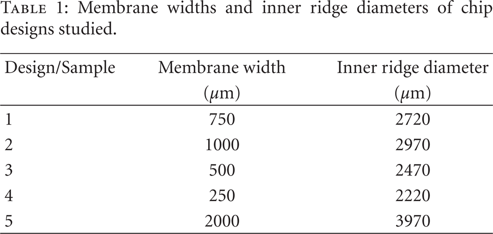
The dimensions in common for these samples are
diameter of the centre hole: 1000 μm,
inner diameter of the membranes: 2000 μm,
thickness of the membranes: 50 ± 1 μm,
width of the ridge: 30 μm,
height of the ridge: 5 ± 0.3 μm,
thickness of the chips: 1050 μm (two chip thicknesses make one sample thickness).
The variable dimensions are
outer diameter of the membranes, and thus their respective spans (250 to 2000 μm),
ridge diameter (since the ridges are always centred on the spans).
The stainless steel nipples were prepared in an automated grinder/polisher to obtain a close to perfectly flat contact surface normal to the axis of its opening. Soft cloths and a diamond powder with a grain size down to one micrometer were used in the last polishing step resulting in a slight rounding of the outer and inner edges of the nipple.
The micropart samples—one per design in Table 1—were realised by silicon fusion bonding two 525 μm thick, 4 inch diameter, (100) orientated silicon wafers (Wacker, Germany). Prior to this, both were patterned by standard UV lithography and structured by means of deep reactive ion etching (DRIE). The bottom wafer was masked in one step to define the chip contours and etched from one side. The other wafer was patterned with three masks per side: the top side to define the ridge, the centre hole, and the chip contour, and the bottom side to define the channel for pressure equalization, the membrane thickness, and the centre hole and the chip contour. (As evident from Figure 3, these two parts are denoted unstructured and micromachined, resp., to distinguish their effective surfaces.) Finally the samples were released by dicing the tiny unetched bridges that held them in the bonded wafers. The individual processes are described in, for instance, [17].
3. Experimental Setup and Calculations
3.1. Experimental Setup
Figure 4 shows schematically the experimental setup and a cross section of the test chamber with a high-pressure part of stainless steel and a vacuum part of aluminium assembled with a soft aluminium gasket in between. The high-pressure side is connected to a helium cylinder via a pressure regulator, and the vacuum side to a helium-triggered leak detector (HLT100, Baltzers) served by a turbo pump.
Schematic experimental set up, (a), and cross section of the test chamber with sample mounted inside, (b).

A cylinder of aluminium internally threaded from both ends is assembled to the high-pressure part, encapsulating the nipple, and serving as a guide for the sample and the supporting insert. When the stop screw is driven into the aluminium cylinder by a torque wrench, the sample is pressed parallel to the nipple by the supporting insert since its end is conical and its diameter slightly smaller than the inner diameter of the aluminium cylinder. The interface between the nipple and the sample constitutes a dismountable connection between the two pressure zones. A heater element is wound around the high-pressure part, and a temperature sensor is inserted in the bulk material of the high-pressure part to measure the temperature close to the interface.
The power to the heater, and data sampling from the temperature sensor and pressure sensor, as well as the leak detector are computer-controlled in the Labview environment (version 7.0, National Instruments) and by means of a PCI card (PCI-1711S, Advantech). Cooling by means of liquid nitrogen and switching of leak rate measurement ranges are controlled manually.
All aluminium parts with an exception for the gasket are made from Dural (US: SS4338), and the stainless steel parts from alloy ASTM316 (European: EN1.4436).
3.2. Calculation of Torque Required for Assembly
Finite element analysis was employed for calculation of the membrane axial force, F a,x , theoretically needed for full deflection of the stiffest membranes in the sample series. From this, the torque, T, needed to apply to the stop screw M10 × 1.5 mm could be calculated [19] through

where θ n is an effective angle governed by α and β, the lead and thread angles, respectively, d p the pitch diameter, and μ the friction coefficient between stainless steel and aluminium.
3.3. Calculation of Thermal Expansion of the Assembly
Central to this study is the fact that the connector and fixture parts have different expansion coefficients allowing the sample to separate from the nipple on heating. Should the materials be selected in the reverse order, the net expansion of the assembly would be positive on lowering the temperature. Obviously, if the parts involved have the same thermal expansion coefficient, the assembly would be, at least theoretically, leak tight at any temperature. However, there are reasons for using ductile construction metals for macroscopic structures, and brittle semiconductor materials for MEMS parts. With this as a basis, the following estimation of the thermally induced merging and separation of the sealing interface of the connector assembly can be made.
The aluminium cylinder has a larger thermal expansion than all the parts inside (Figure 5). Assuming negligible constraint of the expansion, and with reference to Figure 5, heating of the assembly results in a net thermal extension,

because the cylinder constituting the axial constriction for the parts inside is made of aluminium (Al), the sample of silicon (Si), and the nipple, supporting insert and stop screw, working collectively in this respect, of stainless steel (SS).

Schematic representation of the assembly for calculation of the net thermal expansion. (Al, Si, and SS denote aluminium, silicon, and stainless steel, resp.)
In general, the thermal expansion of a part is given by
4. Experimentals
In essence, the samples, when evaluated as connectors, were subjected to either temperature cycling from room temperature via 100°C and
4.1. Assembly
A torque of about 0.5 Nm was applied to the stop screw in all assemblies, with an exception of 0.7 Nm for the assembly with sample 5, which was turned upside down for use as a flat (nonridged) reference. During assembling, the sample and the supporting insert were allowed to rotate freely with respect to the nipple. Axial alignment, other than the passive one of the aluminium cylinder with its 0.25 mm radial margin to the chip and insert, was not made of any part of the assembly.
The samples, the nipples (integrated with the high-pressure part), and all other parts of the test equipment were handled in a normal laboratory after processing of the samples in a clean-room environment. However, caution was taken to keep the sealing surfaces clean from particles and avoid scratching. Nitto SWT10 (alternatively SWT20) tape was used to remove particles before giving the surfaces a rinse with acetone followed by isopropanol, and blowing them dry with nitrogen. Immediately, thereafter, the parts were assembled inside the aluminium cylinder (Figure 4(b)), and the cylinder, which now was assembled on the high-pressure part, mounted into the test chamber of the vacuum part.
4.2. Tests
A temperature cycling test, comprising a heating, a cooling, and a thawing phase, was conducted for sample 1. A power of 48 W was used to heat the test chamber and sample from room temperature to about 100°C. In the cooling phase, after shutting off the heater, the test chamber was immersed in liquid nitrogen, already from the highest temperature, until the test chamber reached
To minimize particle contamination on reassembly, the samples were detached by retracting the stop screw 3 mm, and then tightening it back again with the same torque. Occasionally, helium flushing was performed to assure that the parts indeed had been separated.
The second type of test was heating until leaking. These tests were made on virgin assemblies to investigate the upper temperature limit and understand the sealing mechanism. To avoid saturation, the mass spectrometer of the leak detector had to be switched off before the leak rate exceeded the upper operational limit. A heat-until-leak test took about 15 to 25 minutes.
Prior and subsequent to all tests, the contact surfaces were investigated by means of optical microscopy. In addition, White Light Interferometry, WLI (WYKO NT2000, model PZ-06-CS-SF, Mikro Precision Instruments, USA), was used to quantify the topography.
5. Results
The results from stress calculations for the deflected membranes of all samples are presented in Table 2, where F a,x are the FEM-calculated axial forces needed to deflect the membranes fully, Pridge the corresponding contact pressure at the ridge, and Fapp the applied axial forces. The ratio Fapp/F a,x in Table 2 expresses by how many times the applied axial force overrides the calculated force F a,x needed to deflect the membrane and make the solid part of the sample reach the nipple surface. In the FEM calculation of the F a,x and Pridge, the ridge surface was displaced to the plane of the solid part of the samples, so that no indentation of the ridge in the nipple was taken into account. Therefore, the high values of 359 and 2218 MPa in the column Pridge should be interpreted as the ridge of these samples having indenting in the nipple, since the elasticity limit of the nipple of 250 MPa (established by measurement) has been exceeded and the true contact area enlarged.
Theoretical contact pressure (stress) on the ridge for the axial force, F a,x , calculated to fully deflect the membrane and the ratio of the actual force, F app , to this.

The results from all leak tests are presented with temperature and leak rate versus time. Figure 6 shows the results from the temperature cycling tests of sample 1, assembled for the third and fourth times to the same nipple, and with a helium pressure of 8.5 bar. The test results from the first and second assemblies were almost identical to that from the third, and are therefore omitted here. The leak rate after the fifth assembly exceeded the detection range. There was an apparent increase in leak rate when airflow was directed to the test chamber in the thawing phase. A separate test confirmed air leakage through the aluminium gasket.
Leak test after third, (a), and fourth, (b), assemblies of sample 1 to the same nipple.

The pictures in Figure 7 were taken of sample 1 and its corresponding nipple after five assemblies. Measurement on the nipple by means of WLI revealed discontinuous imprints with depths of a few nanometres. Pattern identification resulted in three sets of rings (Figure 7(c)) with diameters corresponding to those of the ridge and the inner solid silicon region of the sample (Table 1). Examination of the chip after cleaning with acetone and isopropanol showed that it was seemingly intact.
Pictures of sample 1, (a), and the belonging nipple, (b), after five times of assembling. The two cleaner zones on both sides of the bright ridge in (a) indicate that the membrane was not in contact with the nipple. The circles in panel (c) (otherwise equivalent to (b)) are drawn on the identified patterns of the ridge imprint on the nipple surface.

Figure 8 shows the result from the heat-until-leak test of sample 2 assembled to a fresh nipple. Not readily visible in these charts, but from the raw data, is a small but significant increase in leak rate from

Leak rate and temperature as a function of experiment run time for sample 2 assembled to a fresh nipple. The mass spectrometer was shut off shortly after running out of range (i.e., at 136°C, after 745 seconds).
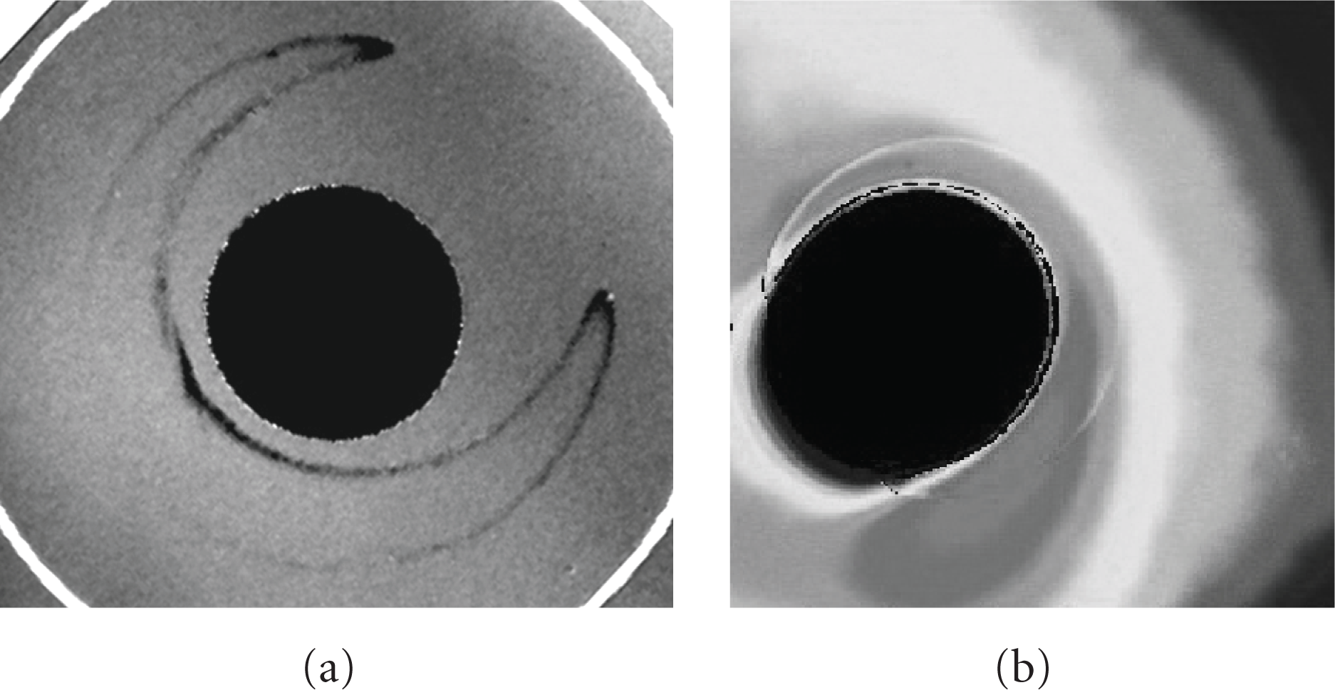
The pictures in Figure 9 were taken using WLI on sample 2 (with a large membrane span, Table 1) and its nipple after this test. The crescent pattern close to the hole in the sample indicates this part having been in contact with the nipple. At most, and on its contour, this imprint was 20 nm deep. However, no clear imprint from the ridge could be found on the nipple surface.
White light interferometry picture of sample 2, (a), and the nipple, (b). The crescent pattern close to the hole indicates that contact between the inner solid silicon part and the nipple has occurred. Note: the thin, upper-right curve on the nipple corresponds to the inner curve of the crescent pattern on the sample.
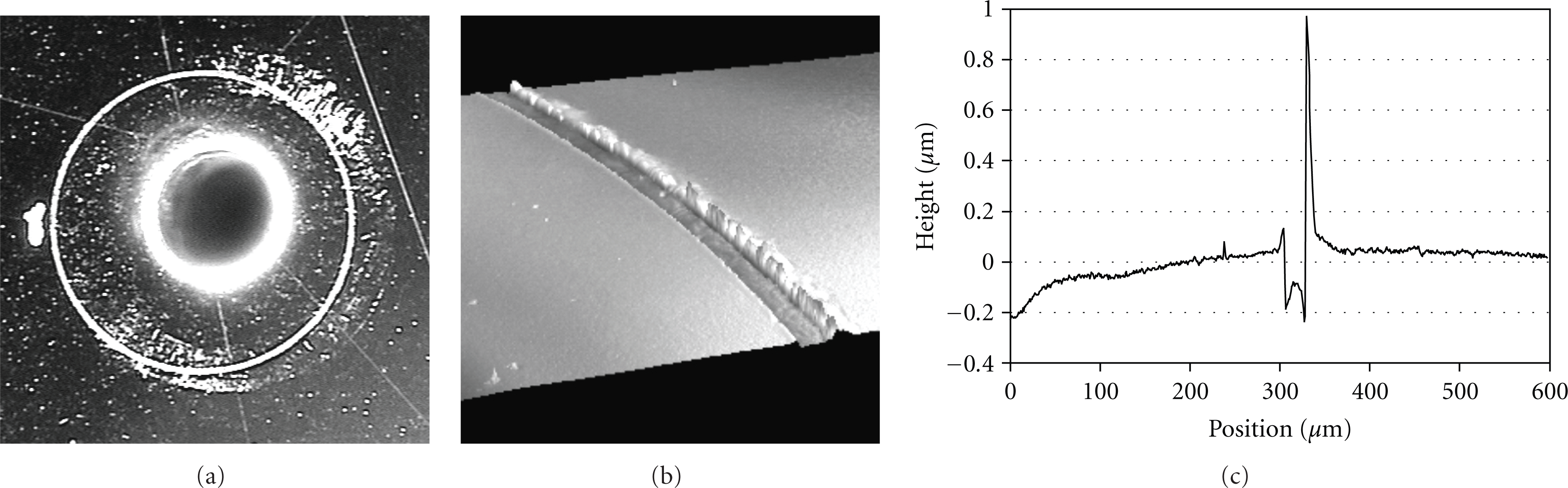
A test with a first-time assembly with sample 3, whose membrane has a shorter span than that of samples 1 and 2 (Table 1), was made in the same way, but with a second heating after the first out-of-range leak and subsequent cooling down to a temperature of 82.5°C, at which the leak detector could be switched on again (Figure 10). The temperature change from the onset of leak to the leak being out of detection range was only 1°C (90–91°C). The result of the WLI measurement shows a ridge imprint with a depth of about 0.2 μm on the nipple (Figure 11).

Leak rate and temperature as a function of experiment run time for a first-time assembly with sample 3 heated two consecutive times—the first from room temperature.
Picture of the nipple after the heat-until-leak test with sample 3, (a), and surface profile imaging and quantification by means of white light interferometry, (b) and (c).
A first-time assembly with sample 4, whose membrane is the stiffest in the series (Table 1), was tested, but with only one heat-until-leak cycle (Figure 12). Also here, and not visible in this chart, but from the raw data, a significant increase in leak rate from

Leak rate and temperature as a function of experiment run time for a first-time assembly with sample 4.
Picture of the nipple, (a), after the heat-until-leak test with sample 4, and a surface profile acquired with white light interferometry, (b).

The last heat-until-leak test was conducted on a first-time assembly with sample 5, which was turned up-side-down to offer its flat rigid side for sealing. The ridge and membrane, now on the supporting insert side, could still be deflected on assembling, however. The purpose of this test was to investigate the necessity of the ridge as a sealing element. Figure 14 shows the result. The left flank on the leak rate line at 82°C (i.e., after 440 s) originates from the changing of range of the leak detector, and the vertical line on the right hand side from switching it off as it ran out of the detection range at 115°C.

Leak rate and temperature as a function of experiment run time for a first-time assembly with sample 5, turned upside down to examine sealing performance of an unstructured silicon surface.
6. Discussion
Generally, two perfectly conformal and smooth surfaces pressed against each other constitute a leak tight interface even at moderate mating forces. For rough or nonconformal surfaces, a soft or weak material and an appropriate contact force may deform one or both of the surfaces to form a leak tight assembly. However, components prone to plasticization comply worse with a reassembly requirement, and components prone to substantial elastic deformation usually negotiate extreme temperatures less well. In the concept investigated here, the micromachined surface of the samples is rather flat, but the surface of the nipple not as the outer and inner edges of it is rounded off during polishing, especially when a soft cloth is used. The extent of this rounding depends on the force applied, and the speed and duration of the polishing process. Many preliminary tests failed completely because the resulting curvature close to the opening of the nipples approached the ridge of the silicon parts. Thus, manufacturing of the nipples is a critical part of the work.
6.1. Performance and the Reassembly Issue
The temperature cycling tests are a way of qualifying the connectors and verifying their operational temperature range and reliability. Figure 6, for instance, showed that the performance of the reassembled connector was essentially reproducible with an exception for a leak rate fluctuation probably due to helium from the surrounding air leaking into the test chamber though the aluminium gasket. It should be remarked that the helium content in the air of the laboratory was enhanced because of repeated disassembling and helium flushing. Were it not for this ambient, the background leak rate would be stable at about 2.0×10⁻⁸ scc/s GHe. Thus, the higher leak rate levels in both charts (
6.2. Sealing Mechanism
In the following, the analysis of the results from the tests with the five samples will be focused on identification of which parts of the sample, or which combination thereof, are the effective sealing elements. The heat-until-leak tests are aimed to determine the highest working temperature of the connector, but they also help to derive the sealing mechanism. Since samples, nipples, and assembling procedures differ slightly, only a very large number of heat-until-leak tests would give this work full statistical significance. It should be stressed that all heat-until-leak tests were performed on first-time assemblies only.
6.2.1. On the Test with Sample 1
The appearance of sample 1 and the belonging nipple (Figure 7) reveals that the ridge and solid silicon regions, but not the membrane, of the sample were in direct contact with the nipple. Because the ridge made such a shallow imprint on the nipple, the membrane had to be almost fully deflected. This hypothesis is supported by the fact that the applied axial force overrode, with a factor of 18, the force needed to deflect the membrane fully (Table 2) without causing a contact pressure (Pridge) exceeding even half the elasticity limit of the nipple, being approximately 250 MPa (as estimated from a Vickers hardness measurement).
Since there are only three sets of circles (Figure 7(c)) and the first three tests yielded the best and identical results, it can be assumed that the sample clung to the same spot on the nipple, even though the stop screw had been loosened a couple of turns, the almost concentric circle set (marked “Solid 1” and “Ridge 1” in Figure 7(c)) is likely to correspond to these first tests, and the two remaining circle sets crossing each other, could originate from the fourth and fifth tests.
In the first three tests, any part of the sample in contact with the nipple could be the sealing element. In the subsequent tests, the inner solid silicon region of the sample is not likely to be the sealing element, since the poor alignment in combination with the rounded off edge of the nipple's opening creates a gap between them. It is not likely either that the ridge alone is the sealing element since it crosses the imprint from the prior tests.
In the fifth test the leak rate was out of the detection range, and no part of the sample managed to seal the interface. (A reasonable explanation might be the added contamination on the contact surfaces during unfiltered helium flushing.)
Due to the insufficient thermal expansion of the assembly, in none of the five tests should the solid silicon regions of the sample disengage from the nipple surface at the highest temperature of these tests, because this normally occurs at an even higher temperature (see the heat-until-leak test with sample 2, discussed below). Hence, the outer solid silicon region of the sample in contact with the nipple should be the primary sealing element. The leak tight assembly with the backside of the sample 5 strengthens this hypothesis.
6.2.2. On the Test with Sample 2
The crescent patterns on sample 2, having a weaker membrane than sample 1, and its nipple (Figure 9) are the evidence of a direct contact between them. However, this is not likely to provide sufficient sealing by itself as it is not a continuous feature. The ridge and the outer solid silicon region should be in direct contact with the nipple since the applied axial force exceeded by 37 times the force needed to deflect the membrane fully (Table 2). Hence, the sealing probably takes place at either or both of these parts of the sample.
The net thermal expansion
6.2.3. On the Test with Sample 3
From the ridge hypothesis above, the effect of making a substantial imprint with the ridge should be examined. With a calculated net thermal expansion of
The fact that the nipple is plastically deformed under the ridge agrees with the calculation declared in Table 2. The applied force being 6 times the FEM calculated force needed to deflect the membrane fully predicts that also the solid silicon regions of the sample had to be in contact with the nipple, although this was not verified from microscopy (Figure 11(a)). This, together with the quite abrupt run out of detection range in this test, strengthens the interpretation of the test with sample 2 discussed above. The sudden increase of the leak rate can perhaps be explained by an equally sudden extraction of a ridge released from a lateral clamping between the inner sidewall of the ridge and the imprint in the nipple inflicted by the mismatch in coefficient of thermal expansion.
6.2.4. On the Test with Sample 4
Also in the case of sample 4, the calculated net thermal expansion of the assembly (
The stiffness of the membrane and the depth of the imprint suggest that a sample with a ridge on solid silicon instead of a membrane would work as well. Such a connector would be forgiving to the counter surface but at the cost of the ability to reassemble the same connector. An exchange of either the nipple or the micropart—then with a different ridge diameter—is a natural solution to this.
6.2.5. On the Test with Sample 5
Eliminating the ridge as emulated by the use of the backside of sample 5 asks for either a cleaner, smoother, and more conformal interface, or a larger deformation. Here a torque of 0.7 Nm, which is 0.2 Nm higher than the torque in all other tests, was needed to create a leak tight sealing. It is difficult to separate plastic and elastic deformation in this case, leaving it to a speculation whether it is possible to have an advance note on the seal breakdown or not under these conditions. Figure 14 reveals a sudden although stepwise course attributable both to the relief of an elastic bias of the system or a more distributed contact prolonging the separation.
6.3. General Remarks
Pictures of nipples (especially Figure 11(a)) show that the sharp-edged silicon ridge has scraped its way on the nipple surface during assembly before gaining enough friction to stop the lateral movement. Needless to say, this is detrimental to the nipple and of possible effect for the prospect of reassembling, although guides preventing this motion could easily be implemented in the connector. Also, in the case of sample 2 with its weak membrane, scraping marks could not be found which leaves room for some optimization. Again, it should be noted that the samples were found intact after disassembling.
In heat-until-leak tests, the breakdown exhibits a sort of early warning. Sample 2 with its weak membrane provided a smooth warning of approximately 129 s in comparison with the 1 s of the stiffer sample 3. A very stiff membrane, on the other hand, causes a deep imprint connected with an even earlier warning as observed with sample 4 (Figure 12).
To compare the five tests, going from the last to the first, it is clear that experiment with sample 5 proved that two perfectly smooth surfaces pressed sufficiently hard against each other constituted a leak-tight connection. Experiments with samples 3 and 4 proved that with the silicon ridge being imprinted in the softer nipple the connection also became proof. Experiment with samples 1 and 2 gave the evidence that any part of the sample on the side in contact with the nipple can be the sealing elements.
7. Conclusions
Experiments conducted in this work have demonstrated that a reconnectable fluidic connector between a stiff and brittle silicon-based microsystem and a weaker and ductile macropart (here a steel nipple) is feasible. The equipping of the micropart with a sharp 5 μm high ridge on a membrane around the fluidic opening improved the thermal endurance of the coupling and also, due to the difference in coefficient of thermal expansion of the involved materials, provided an early warning signal before breakdown of the sealing with increasing temperature. In addition, the ridged micropart was found to require less sealing force in comparison with a flat reference sample, which, on the other hand, should be easier to manufacture. Although not specifically studied here, microscopic investigation of the samples indicates that the ridged microparts are forgiving to particle contamination of the interface in contrast to the flat reference. However, a ridged membrane requires careful optimization not to make an indentation in the softer counterpart and so decrease the prospect of reassembly. However, for a permanent connector a stiff membrane giving a deep indentation of the ridge in the softer counterpart is preferable. In general, the connectors tested were able to maintain a close to negligible leak rate of
Footnotes
Acknowledgments
The authors would like to thank the European Space Agency for financial support of the Micro/Nano Satellite Technologies project, of which this work is a part, and Robert Simonović, Institute of spacecraft systems, Stuttgart University, Germany, for a fruitful collaboration.