
Abstract
Response of fiberglass epoxy composite laminates under low velocity impact loading is investigated using LS-DYNA®, and the results are compared with experimental analysis performed using an instrumented impact test setup (Instron dynatup 8250). The composite laminates are manufactured using H-VARTM© process with basket weave E-Glass fabrics. Epon 862 is used as a resin system and Epicure-W as a hardening agent. Composite laminates, with 10 layers of fiberglass fabrics, are modeled using 3D solid elements in a mosaic fashion to represent basket weave pattern. Mechanical properties are calculated by using classical micromechanical theory and assigned to the elements using ORTHOTROPIC ELASTIC material model. The damage occurred since increasing impact energy is incorporated using ADVANCED COMPOSITE DAMAGE material model in LS-DYNA®. Good agreements are obtained with the failure damage results in LS-DYNA® and experimental results. Main considerations for comparison are given to the impact load carrying capacity and the amount of impact energy absorbed by the laminates.
1. Introduction
Fiber-reinforced composite materials are extensively used in modern aerospace industry because of their low specific weight with high specific modulus. However out of plane loading, such as impact loading, can cause severe drop in load carrying capacity of these laminates. This drop in load carrying capacity is mainly because of the internal damage of matrix or fiber, which in many times is hard to detect just by visual inspection. In the current work a series of experiments were performed to study the effect of increasing impact energy on fiberglass/epoxy composite laminates in terms of their impact load carrying capacity and impact energy absorption. Fiberglass/epoxy composite laminates are particularly considered as they show superior performance under out of plane loading as opposed to carbon/epoxy laminates, which are strong under in-plane loading. In broad sense the study of low-velocity impact loading on a composite material is divided in three categories, (1) experimental study, (2) analytical study, where a failure model of composite material is proposed, and (3) numerical analysis, mainly using finite element analysis.
Numerous experimental research efforts have been carried out to understand the behavior of composites under low velocity impact applications. When the composite laminate is impacted with the foreign object, the impact dynamics in the vicinity of the impact region becomes very complex [1]. Wang et al. [2] in his research paper discussed the low velocity impact properties of the 3D woven basalt/aramid hybrid composites using experimentally collected data. Tan et al. [3] studied the effect of impacting projectiles with different geometries on the high strength filler fabric. Cheeseman and Bogetti [4] studied the factors affecting the impact forces and the strains of ballistic impact on composite laminates. Bazhenov [5] presented the energy dissipation by bulletproof aramid fabric, while Iremonger and Went [6] studied the mechanism of penetration for ballistic impact on composite armors. Hosur et al. [7, 8] and Siow and Shim [9] studied behavior of various types of composite laminates under low velocity impact and compared their results with ultrasonic c-scans of the damaged laminates. Pearson et al. [10] did global-local assessment of woven composites, where global measurements were taken from low-velocity impact experiments and local strain measurements were obtained using optical Fiber Bragg Grating (FBG) sensors and mapped the failure for two- and three-dimensional woven composites.
Many researchers proposed analytical models for progressive damage in fiber-reinforced composite laminates. Parga-Landa and Hernández-Olivares [11] presented an analytical model to study the impact behavior of soft armors. Robbins and Reddy [12] proposed adaptive hierarchical kinematics approach, which uses variable kinematic finite elements (VKFE) for modeling progressive damage. Shokrieh and Lessard [13, 14] proposed and validated a progressive fatigue damage model for composite laminates. Out of several methods explained above, a damage mechanism proposed by Chang and Chang [15, 16] is used in LS-DYNA® simulations. More detail explanation of this damage model is given in Section 4.1.1.
Apart from these experimental and analytical studies, several numerical simulation approaches are also presented. Mikkor et al. [17] presented finite element model to study the impact behavior of preloaded composites panels. McCarthy et al. [18] studied the bird strike on an aircraft wing leading edge made from fiber-metal laminates using novel SPH finite element approach. Meo et al. [19] studied behavior of composite laminates embedded with shape memory alloy using finite element analysis. Donadon et al. [20] in his research publication proposed a 3D micromechanical analytical model for the study of woven hybrid laminates using CLT. Kermanidis et al. [21] presented a finite element approach for studying the bird impact on the horizontal tail of a transportation aircraft. Ji and Kim [22] used direct numerical simulation to simulate low-velocity impact on 3D orthogonal woven composites.
In modeling woven composites under impact, the experimental and the classical mechanics approach seems to be very expensive and highly complicated. Hence one has to depend on the numerical approaches which are fairly accurate, less expensive and less time consuming. In the present study a finite element approach has been used to model the ten-layered composite laminates using model builder VPG and solved using LS-DYNA® solver. The 10 ply E-glass epoxy laminates have been modeled, and their impact behavior is compared with the experimental results for six different energy levels.
2. Modeling Details
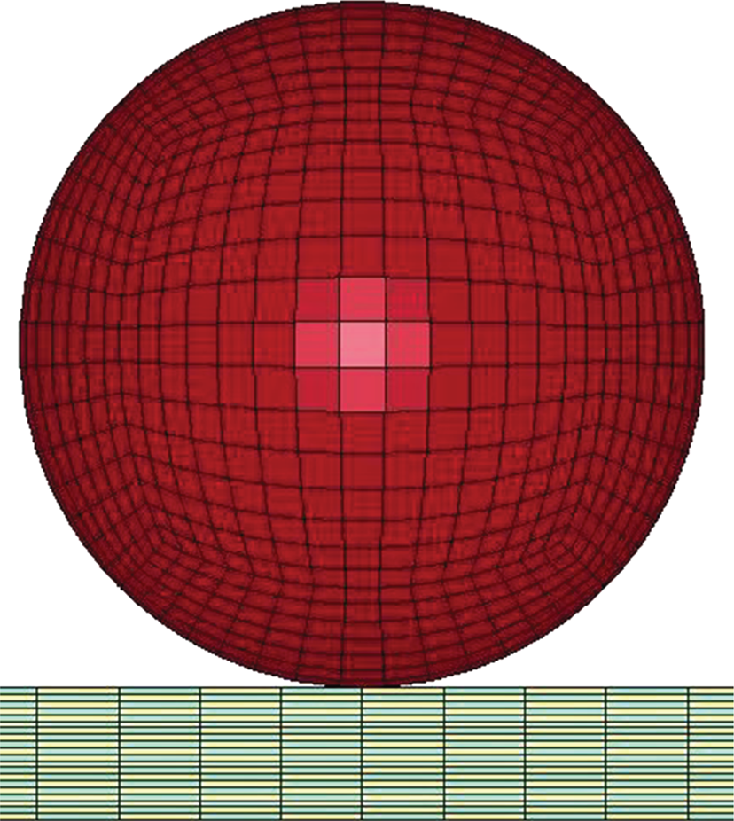
This section provides details of finite element modeling, used to analyze the impact phenomenon. The modeling of the composite laminate is done using a finite element mesh in mosaic fashion as shown in Figure 1(b), to mimic the basket weave pattern shown in Figure 1(a). The laminate model was fully developed using the repeating unit. The repeating unit is the smallest unit that repeats in the whole laminate system in x-y plane. The fabric consists of fibers oriented in two directions, the warp (0°) and the weft (90°). In the model, the warp and the weft of the composite are represented by a unit cell. The unit cell is created using an 8-node solid element. In the unit cell, the warp and the weft are assigned with orthotropic elastic material properties when “no failure” criteria is used. When composite damage model is used to invoke “failure” criteria, additional strength properties are assigned as shown in Table 2. The resultant properties of the composites unit cell are computed using constituents properties, that is, fiber properties and matrix properties together as shown in Table 1. The unit cell consists of unidirectional fibers impregnated in the epoxy resin, which makes it behave as an orthotropic elastic material making it much stronger in one direction (0°) and weaker in the other (90°) direction.
Constituent's elastic properties.
Material properties of a composite laminate.
Basket weave pattern of Fiberglass/Epoxy laminate and corresponding finite element Mesh.

There are many possible ways to compute the unit cell properties, some based on experimental study and other on parametric approaches. The analytical method of computing properties is time consuming, and the parametric approach requires extensive combinations of tests. Chamis [23] in his research paper presents the simplified equations to compute strengths, fracture toughness, impact properties based on the micromechanics approach. The same equations were adopted for computing the resultant properties of the fiberglass/epoxy unit cells.
Total thickness of the fabricated laminates is measured and accordingly assigned to the elements. The layers are stacked over each other, which are in an alternate (0°–90°) fashion to produce 10-layered composite laminates. Care is taken such that one layer of actual weave is equivalent to two layers in the mosaic FE model. Laminates in the impact test machine holding fixture are clamped at all the four sides. To mimic this boundary condition in modeling, all the boundary nodes are fixed in all translations. Also all the boundary nodes are fixed in all rotations. Solid section is assigned to both warf and weft to simulate the solid structure of the laminate.
The ball is modeled to simulate the 12.7 mm (dia) solid steel impactor of the impact machine. Four-nodded solid quad elements with higher mesh density are assigned to ensure that the cell size of ball is smaller than the cell size of either composite laminate as shown in Figure 2. The steel ball is assigned with solid section similar to the composite laminate. Impactor ball is constrained in 5 degrees of freedom (x and y translation and 3 rotation) allowing its movement only in z direction. The effective density equal to 7860 (kg/m3), Young's modulus equal to 200 GPa, and Poisson's ratio equal to 0.3 are assigned to the material of the ball.
Finite element mesh of an impactor.
In the process of ball impacting the composite plate, the impact starts with the ball touching the composite plate (point to surface contact) and progresses as a surface-to-surface contact. In LSDYNA® an automatic surface-to-surface contact has been assigned between warf and ball and weft and ball to accommodate the impact initiation and the impact progress. The impact time duration, that is, the termination time, computation time step, and output time step are specified in the control cards of LS-DYNA® to control the computational run and to get the output at desired time interval. The output is in the form of binary data, which can be analyzed using the LS-PREPOST postprocessor.
3. Experimental Details
This section presents detailed explanation of the experimental study conducted.
3.1. Fabrication Using H-VARTM© Process
Basket weave woven-roving FGI 1854 E-glass fabrics are manufactured by Fiber Glass Industries, Inc. with EPIKOTE Resin 862 (Bisphenol-F (BPF) epoxy resin) and EPIKURE Curing Agent W (Non-MDA, aromatic amine curing agent) are used to fabricate all the laminates. The fabrication of the composite panels is done using the H-VARTM© (Heated Vacuum Assisted Resin Transfer Molding [25]) process. Four square test coupons of size 0.152 m (6 in) are cut from each panel, which are clamped in impact test machine. The clamped area is 12.7 mm (0.5 in) from all the sides. The total impacted area is 0.127×0.127 m2. Figure 3 shows schematic of H-VARTM© setup.

Schematic of H-VARTM© process.
3.2. Impact Test Procedure
All the impact tests are performed using the DYNATUP 8250 impact drop tower device as shown in Figure 4. The low velocity impact test facility consists of a drop tower equipped with an impactor and a variable cross-head weight arrangement, a high-speed data acquisition system, and a load transducer mounted in the impactor. In this study the gravity mode is used for all low velocity impact tests. The cross-head/impactor weight is kept constant for all tests. The cross-head weight is maintained at 5 kg, and including the weight of the impactor, which is 0.45 kg, the total weight becomes 5.45 kg. The low velocity impact facility is equipped with instrumentation to measure the velocity prior to impact. The high-speed data acquisition system has the capability of storing the entire impact event and produce load-time, load-deflection, and energy-time curves. The objectives of the preliminary impact tests are
to establish the energy levels and drop height for the incipient damage threshold or lower bound,
to establish the energy levels and drop height for penetration or the upper bound.
DYNATUP 8250 test setup.

To achieve the above objectives, a series of impact tests are performed and are discussed in the following paragraph. To start with, a random drop height is selected to perform the low velocity impact test on the woven composites. After impact, the specimens are examined for damage. The impact height is varied until the impact load-time history plots indicated no impact damage. The energy level corresponding to this drop height is called threshold energy level or lower bound. To establish the energy level for the upper bound (i.e., beginning of penetration), the drop height is selected such that there will be a decrease in impact load carrying capacity of the laminate if this height is increased further. Once the lower and upper bound energy levels were established, the difference in the drop heights was calculated. The loading range is divided into six (6) successive drop heights, and the three impact tests are carried out for each drop height to obtain the statistical accuracy. This series of tests gives sufficient data to analyze the damage characteristics and to study the progression of damage in fiberglass/epoxy composite laminates.
4. Results and Discussions
This section present a discussion of (a) comparative results obtained from experimental study and LS-DYNA® simulations and (b) progressive damage.
4.1. Comparative Results
Comparative plots of experimental and LS-DYNA® results for E-Glass/Epoxy laminates under six different impact energy levels are reported in this section. LS-DYNA® runs are conducted with and without the failure criteria and compared with experimental results. The lowest energy level is chosen from the incipient damage seen in the test, and the impact energy is increased with equal increments to incorporate six energy levels. Table 3 presents experimental results for six drop heights (impact energy levels) of an impactor with three repetitions per drop height. Average value of three runs for each drop height is considered in all the comparison plots. As seen in Table 3, the maximum load carrying capacity of E-glass laminates increases with the increase in impact energy. This indicates that the maximum load carrying capacity (max. impact load) of the laminates has not yet reached to the saturation level, where considerable damage is seen.
E-Glass epoxy experimental results.

To understand the behavior of E-glass/epoxy laminates with respect to time, comparison plots of “impact load” and “impact energy loss” versus time are given in Figures 5 and 6, respectively. As seen in Figure 5 when “no failure” criteria is used, the material overpredicts maximum load carrying capacity, and the impact time is less than the experimental values. Since elastic material is used and no damage mechanism is incorporated in “no failure” LS-DYNA® runs, it justifies the increasing trend of impact load with overpredicted values. The results indicate that the material with “no failure” criteria is slightly stiffer than the actual material. When the “failure” criteria is invoked, it can be seen that the loading versus time plot is in better agreement with experimental results.
Impact load versus time plots for E-Glass/epoxy laminates at six impact energy levels.

Impact energy loss versus time plots for E-Glass/epoxy laminates at six impact energy levels.

To get more insight of composite laminate behavior, impact energy loss versus time plots for six energy levels are shown in Figure 6. When “no failure” criteria is used, that is, for orthotropic elastic material, no energy is absorbed by the laminate during the impact. Consequently the energy curve reaches to zero at the end of impact showing material's elastic deformation. In experimental case and where “failure” criteria is invoked, the deformation is not elastic because of the damage and impact energy loss is not zero. However, when “failure” criteria is used, the actual absorbed energy is overpredicted. The subsequent section (Section 4.1.1) presents detail discussion of failure criteria invoked in LS-DYNA®.
4.1.1. Invoking Failure Criteria
S1, Longitudinal Tensile Strength.
S2, Transverse Tensile Strength.
S12, Shear Strength.
C2, Transverse Compressive Strength.
α, Nonlinear Shear Stress Parameter.
In its simplest form the model represents the orthotropic material failure without considering the interlaminar delamination. The model does have a provision to incorporate laminated shell theory to invoke the transverse shear deformation, which is insignificant for low velocity impact problem because primarily failure occurs because of the in-plane stresses in the laminate and small amount of crushing stresses.
The in-plane failure is often the dominant mechanism in tensile failure of fiber-dominated laminated composites. The three different in-plane failure modes are given as matrix cracking, fiber-matrix shearing, and fiber breakage. When the certain element in the FE model is failed as mentioned in any of the failure modes, certain parameters are set to zero. Consequently the load carrying capacity of that element reduces to zero.
In the present problem of low velocity impact the composite damage can be addressed as a combination of matrix failure and fiber failure. Actual failure of the laminate initiates when the first matrix cracking occurs. It then continues when the first fiber breaks and when substantial number of fibers break the element which in turn loses its load carrying capacity completely, which we call the failure of the laminate. The complete span between damage initiations till complete failure of the laminate is very complex to model because at every loading stage the load is shared by matrix and fibers. Also at every failing stage an interlaminar failure occurs along with the progressive damage of the fibers impregnated in the matrix resin. In the mosaic model when the failure stress is reached at any point in the element, the element completely looses its load carrying capacity, and further load is shared by surrounding elements eventually causing them to fail.
In order to bridge the gap between the simple orthotropic material failure model, that is, Chang-Chang Composite Failure Model and the interlaminar progressive damage material model, it is necessary to counterbalance the loss in strength by making failure criteria much stiffer to mimic the actual failure of the laminate which can then be extended over the complete loading range. After numerous iterations, we found that the Enhanced Composite Damage Model (Material model 22 in LS-DYNA®) gives superior results for mosaic model.
The mosaic model in LS-DYNA® delineates soft impact response for higher impact energy levels because of the above-mentioned reasons. The impact load-time response seems to be in good agreement with the experimental response. However because of the successive damage in the elements the energy loss in the simulated model increases as the impact energy level increases.
4.2. Progressive Damage
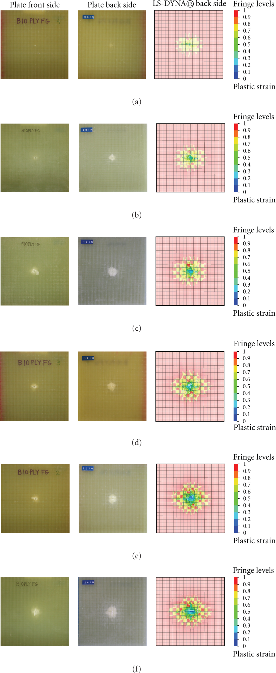
Figure 7 shows the progressive damage due to increasing impact energy levels. From the experimental impacted specimen, it is observed that the damage is prominent on the back face of the laminate, and its negligible on the impacted surface over the complete loading range. This is because the top surface of the laminate undergoes compressive stresses and crushing stresses whereas the bottom surface undergoes tensile stresses. The fiber breaking mainly occurs due to the tensile stresses. It is also seen that the maximum damage zone can be seen on the back face of the laminate. The experimental damage zone is compared with the simulated damage zone (plastic strain contour), and it can be seen that the simulated damaged region is in good agreement with the experimental damaged region. In the glass laminates which are semitranslucent, the damage can be easily seen by naked eyes unlike carbon laminates where ultrasonic c-scan will be required to detect the damage area. Figure 7 shows the comparison of the experimental damage area and the simulated damage area. The fringes in the simulated model show the plastic strain contours.
Progressive damage in E-Glass laminate at 6 impact energy levels (a) 5.45 J, (b) 10.9 J, (c) 16.35 J, (d) 21.8 J, (e) 27.25 J, and (f) 32.7 J.
5. Conclusion
In the present study, response of fiberglass/epoxy composite laminates under low velocity impact loading is investigated using LS-DYNA®. The composite laminates are manufactured by the H-VARTM© process using basket weave E-Glass fabrics with the Epon 862 resin system and Epicure-W as a hardening agent. The LS-DYNA® runs are performed using orthotropic elastic material with “no failure” criteria as well as with damage material with “failure” criteria. These results are then compared with experimental drop test results. The experiments are conducted using Instron Dynatup Low Velocity Impact Test Machine. The “no failure” material model in LS-DYNA® overpredicted the load carrying capacity and showed no energy absorption after impact. These results are justified considering its pure elastic behavior, where total energy is regained after impact is complete. However, the “failure” material underpredicted the load carrying capacity and overpredicted amount of impact energy absorbed by laminates. The overprediction of impact energy absorption can be attributed to the basic geometry of the laminate where no undulations between two layers of the laminate are modeled. Since there is only nodal contact contact between warf and weft (mosaic fashion of elements), the total laminate is acting as a softer material than it is in reality. Also, when failure starts to occur, FEA code starts deleting the elements and load carrying capacity decreases. The present study can be easily extended for other weave patterns including twill weave, satin weave, and braided weave composites.
6. Disclosure
G. Chandekar, author of the paper and all other authors, B. Thatte and A. Kelkar, have no direct financial relation with the commercial software (code) LS-DYNA®. Any other commercial or home grown Finite Element code can be used to verify all the results produced in this paper. G. Chandekar and B. Thatte also have no financial gain by using H-VARTM© process of manufacturing E-glass/Epoxy composite laminates. A patent filed by A. Kelkar and Ronnie Bolick is pending on the H-VARTM© process.