
Abstract
As IEEE 802.15.4 Wireless Sensor Networks (WSNs) and IEEE 802.11b/g Wireless Local Area Networks (WLANs) are often collocated, coexistence issues arise as these networks share the same 2.4 GHz Industrial, Scientific, and Medical (ISM) band. Consequently, their performance may degrade. We have proposed a coexistence model of IEEE 802.15.4 and IEEE 802.11b/g networks, which addresses their coexistence behavior and explains their coexistence performance. As an extension of the previous work, a compact testbed was developed and experiments on the coexistence issues between these networks were conducted. The experiments not only validated the theoretical model but also provided more information and insights about the coexistence issues in the real-life environment.
1. Introduction
IEEE 802.15.4 Wireless Sensor Networks (WSNs) are becoming increasingly popular. Because of their applications, for example, in hospitals and home [1], WSNs are often collocated with IEEE 802.11b/g Wireless Local Area Networks (WLANs), which gives rise to coexistence issues as they both operate in the license-free 2.4 GHz Industrial, Scientific, and Medical (ISM) band.
There have been some studies about the coexistence issues between the IEEE 802.11b/g WLANs and IEEE 802.15.4 WSNs [2–5]. Particularly in [5], we presented a coexistence model of IEEE 802.15.4 WSNs and IEEE 802.11b/g WLANs. In two aspects, namely, power and timing, the model addresses the interaction between these two types of wireless networks and explains their coexistence performance. These two aspects jointly impose specific impacts on the performance of IEEE 802.15.4 WSNs and IEEE 802.11b/g WLANs, depending on the coexistence situations. In order to validate the model and get a better understanding of the coexistence issues in real-life situations, we conducted a number of experiments, which will be presented in detail in this paper. The remainder of the paper is organized as follows. Section 2 gives an overview of the IEEE 802.11b/g standard, IEEE 802.15.4 standard, and the coexistence model. Section 3 describes our testbed. The experimental results are presented in Section 4. The conclusion is drawn in Section 5.
2. Overview of IEEE 802.11b/g, IEEE 802.15.4, and a Coexistence Model
2.1. IEEE 802.11b/g
The IEEE 802.11b and IEEE 802.11g standards define the Medium Access Control (MAC) sublayer and the Physical (PHY) layer for WLANs. Both standards operate at 13 overlapping channels in the 2.4 GHz ISM band and the bandwidth of each channel is 22 MHz. The IEEE 802.11b/g MAC employs the Carrier Sense Multiple Access with Collision Avoidance (CSMA/CA) mechanism. Clear Channel Assessment (CCA) is used in the physical layer to determine the channel occupancy [6]. CCA performs Energy Detection (ED), or Carrier Sense (CS), or a combination of two, that is, CCA shall report a busy channel upon detection of any energy above the ED threshold, or a signal with the known features, for example, the modulation and spreading characteristics, or a known signal with energy above the ED threshold. Owing to involving only integrating the square of the received signal or signal envelop over a CCA duration, ED is a universal mechanism that can be deployed in all systems without requiring any knowledge of the type of underlying modulation scheme employed at the physical layer [7]. Therefore, in the heterogenous network environment, only ED can, though unreliably [7], sense the channel occupancy of other types of networks.
Before initiating a transmission, an IEEE 802.11b/g node senses the channel using either ED or CS (or both) to check whether it is busy because of the transmissions by other nodes. If the channel is sensed idle for a Distributed coordination function InterFrame Space (DIFS) time interval the node will transmit a packet. Otherwise, the node defers its transmission. As the channel becomes idle for a DIFS interval, the node will generate a random backoff delay uniformly chosen in a Contention Window (CW), that is,
2.2. IEEE 802.15.4
The IEEE 802.15.4 standard defines the MAC sublayer and the PHY layer. Its operational frequency bands include the 2.4 GHz ISM band. The IEEE 802.15.4 WSNs also employ CSMA/CA for the medium access control. There are two versions of IEEE 802.15.4 CSMA/CA: slotted and unslotted. In this paper, we discuss only the popular unslotted one. In IEEE 802.15.4 WSNs, the channel is sensed only during a CCA period rather than during both a CCA and a backoff period like in IEEE 802.11b/g WLANs. Moreover, if the channel is sensed busy during the CCA period, the size of CW in IEEE 802.15.4 WSNs doubles, and when the number of the channel access attempts exceeds macMaxCSMABackoffs, the maximum number of backoffs the CSMA-CA algorithm will attempt before declaring a channel access failure [8], the pending packet is discarded. We call this kind of packet loss as inhibition loss.
2.3. A Coexistence Model of IEEE 802.11b/g and IEEE 802.15.4 Networks
The coexistence model of IEEE 802.11b/g and IEEE 802.15.4 networks in [5] includes two aspects, namely power and timing, which are described as follows.
2.3.1. Power Aspect
The transmit powers of IEEE 802.11b/g nodes and IEEE 802.15.4 nodes are typically 100 mW [6] and 1 mW [8], respectively. In case of comparable CCA thresholds, the significant difference in the transmit power can result in three distinct regions as illustrated in Figure 1:
a region in which IEEE 802.15.4 nodes and IEEE 802.11b/g nodes can sense each other, a region in which IEEE 802.15.4 nodes can sense IEEE 802.11b/g nodes, but not vice versa, a region in which neither can sense the other, but IEEE 802.15.4 nodes could still suffer IEEE 802.11b/g interference.
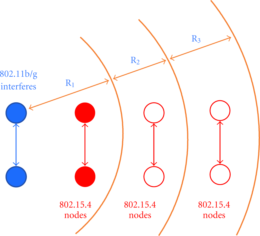
Coexistence regions of IEEE 802.15.4 and IEEE 802.11b/g.
2.3.2. Timing Aspect
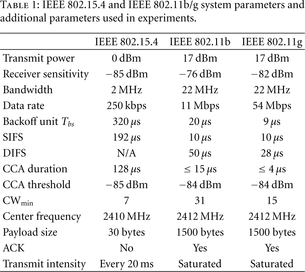
In R1, an IEEE 802.11b/g node and an IEEE 802.15.4 node can sense each other via ED and therefore both of their CSMA/CA mechanisms work, that is, as one is transmitting, the other has to be waiting. IEEE 802.15.4 nodes, however, typically have a 10–30 times longer timing than IEEE 802.11b/g nodes, for example, the backoff slot unit is 320 μs, 20 μs and 9 μs for IEEE 802.15.4, IEEE 802.11b and IEEE 802.11g, respectively, shown in Table 1. The shorter timing gives IEEE 802.11b/g nodes priority over IEEE 802.15.4 nodes to access the channel and therefore causes unfairness to the IEEE 802.15.4 nodes in R1. This is illustrated in Figure 2.
IEEE 802.15.4 and IEEE 802.11b/g system parameters and additional parameters used in experiments.

In R1, the shorter timing gives IEEE 802.11b/g nodes priority over IEEE 802.15.4 nodes to access the channel and therefore causes unfairness to the IEEE 802.15.4 nodes.
In R2, IEEE 802.15.4 nodes can sense IEEE 802.11b/g nodes but not vice versa given the comparable CCA thresholds, because the transmit power of IEEE 802.11b/g nodes is much higher than that of IEEE 802.15.4 nodes. As a consequence, when IEEE 802.11b/g nodes are transmitting, IEEE 802.15.4 nodes have to be waiting, whereas when IEEE 802.15.4 nodes are transmitting, IEEE 802.11b/g nodes are not aware and thus simply proceed to transmit, probably causing an overlapping in packet transmissions. This is shown in Figure 3.

In R2, IEEE 802.11b/g nodes fails to sense IEEE 802.15.4 nodes.
In R3, neither IEEE 802.15.4 nodes nor IEEE 802.11b/g nodes can sense the other. However, IEEE 802.15.4 nodes may still suffer from the IEEE 802.11b/g interference in case of weak IEEE 802.15.4 links, as we will show in Section 4.
3. Testbed
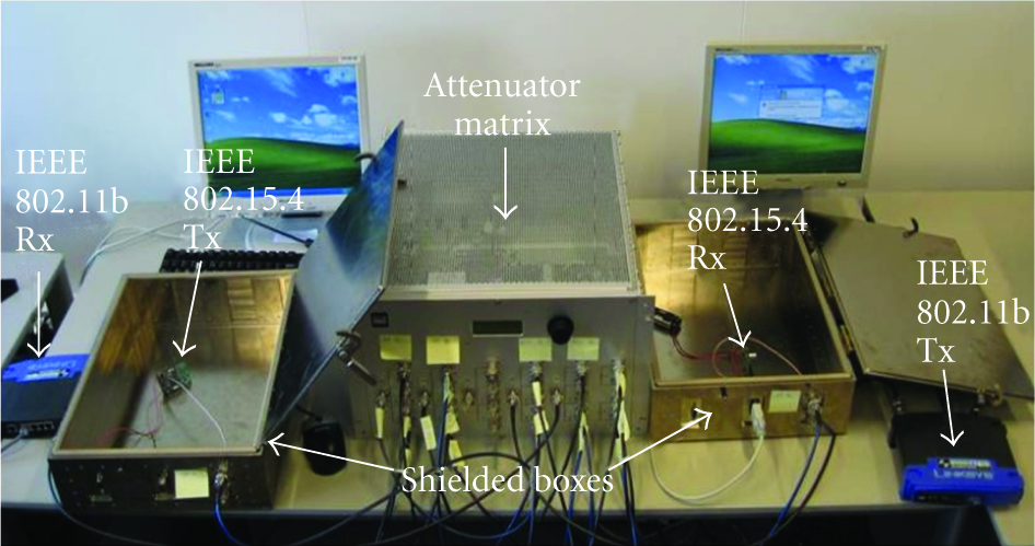
We set up a compact testbed to check whether the three regions described in Section 2.3 exist in practice and to get a better understanding about the coexistence issue. Note that we use only the IEEE 802.11b mode in the test, but the result is also applicable to the IEEE 802.11g case. As shown in Figure 4, the testbed consists of the following items:
two IEEE 802.11b nodes (Linksys WRT54G): a Tx and an Rx, two IEEE 802.15.4 nodes (AquisGrain [9]): a Tx and an Rx, two RF-shielded isolation boxes, one attenuator matrix box, two PCs with testing software.
Testbed of the coexistence model of IEEE 802.11b and IEEE 802.15.4 networks.
The antennas of IEEE 802.11b nodes and IEEE 802.15.4 nodes are connected by cables via the attenuator matrix, the attenuation values of which can be adjusted to emulate the physical distance in a wireless environment. To isolate from other RF interference, IEEE 802.15.4 nodes were put into the RF-shielded isolation boxes such that we got a controlled RF environment, allowing the measurements repeatable.
A functional diagram of the testbed is depicted in Figure 5. The attenuation losses among those nodes are as follows,

Functional diagram of the coexistence testbed.
4. Experiments
In our experiments, the IEEE 802.15.4 Tx constantly sends only broadcast packets and the IEEE 802.15.4 Rx does not send any packets including ACKs. The IEEE 802.11b Tx generates a saturated packet stream and the IEEE 802.11b Rx sends ACKs only. Moreover, we made the IEEE 802.11b Tx and the Rx have the same impact to the IEEE 802.15.4 Tx and to the IEEE 802.15.4 Rx, respectively. We therefore always set the same values for
Before carrying out the experiments, let us calculate R1, R2 and R3, given the parameter values in Table 1.
Given the IEEE 802.15.4 transmit power of 0 dBm and the IEEE 802.11b CCA threshold of Although the IEEE 802.11b transmit power is 17 dBm, only 16.9% falls into the 2 MHz band of IEEE 802.15.4 [10], that is, 9.3 dBm. Given the CCA threshold of By definition, R2 is in between R1 and R3, that is, R2 is the region where 84 dB
Now let us carry out the experiments to identify these regions. For convenience, we start with identifying R1, followed by R3 and R2.
4.1. R1 Identification
To identify R1 and to investigate details of the coexistence behavior of IEEE 802.11b and IEEE 802.15.4 networks, we measure the IEEE 802.11b throughput and the IEEE 802.15.4 packet loss ratio in the following two cases.
4.1.1.
dB (Inhibition Loss Only)
Given such a high attenuation loss, the IEEE 802.11b Tx and Rx have actually no any impact on the IEEE 802.15.4 Rx but only on the Tx. Therefore, in this case, the IEEE 802.15.4 packet loss is not due to collision but only inhibition. As the IEEE 802.15.4 Rx does not send any packets including ACKs in our experiments, only the IEEE 802.15.4 Tx could affect the throughput of the IEEE 802.11b network. Thus, we can adjust only x to observe the impact of the IEEE 802.15.4 Tx on the IEEE 802.11b Tx and Rx.
As an example, in Figure 6, we can see that as
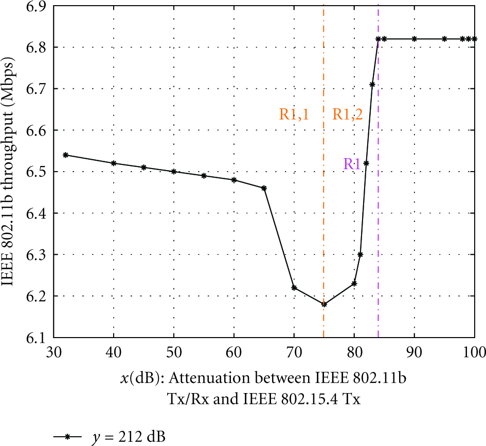
In R1: IEEE 802.11b/g nodes can also sense IEEE 802.15.4 traffic.
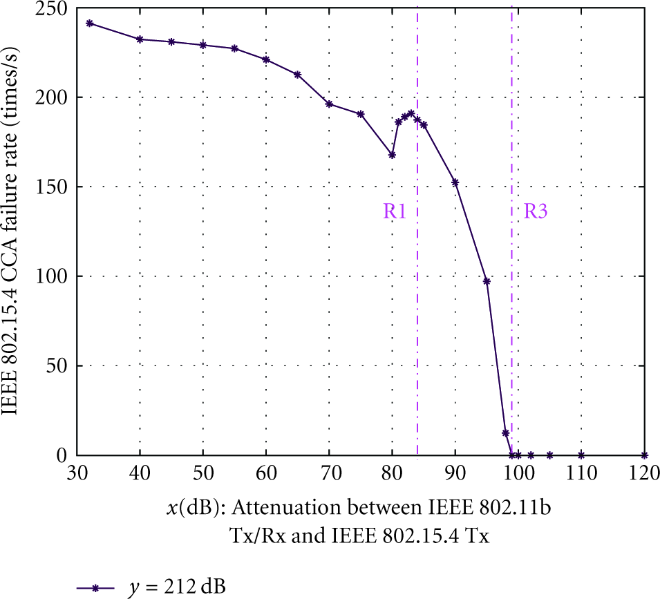
As x increases, we expected the IEEE 802.11b throughput to increase as well because of the weakening IEEE 802.15.4 Tx impact. However, we surprisingly found in Figure 6 that as x increases until about 75 dB, the IEEE 802.11b throughput actually decreases, which suggests that the impact of the IEEE 802.15.4 Tx on the IEEE 802.11b network increases rather than decreases. This is confirmed by Figure 7, in which we can see that for 32 dB
IEEE 802.15.4 Tx CCA Failure Rate.
In Figure 6, for 75 dB
For
In R3: neither can sense the other, but IEEE 802.15.4 nodes could still suffer IEEE 802.11b/g interference.
Note that the curve of “inhibition loss only (
It is worthy of noting that according to [2–4], IEEE 802.15.4 WSNs has little impact on the IEEE 802.11 WLANs performance. This conclusion is true in general, but may not hold in some cases. For example, in Figure 6, we see that for 70 dB
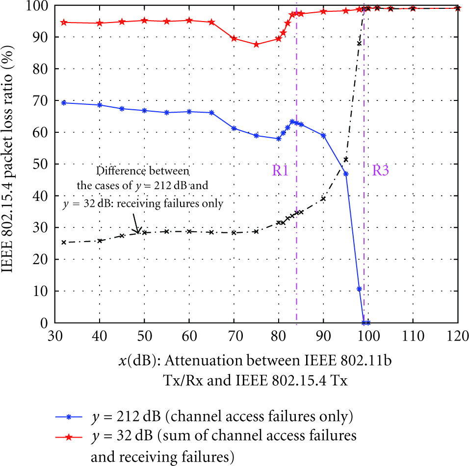
Although R1 has been identified, to reveal more details of the coexistence behavior of IEEE 802.11b and IEEE 802.15.4 networks, with an emphasis on the impact from the IEEE 802.11b traffic on the IEEE 802.15.4 network, we further measured the IEEE 802.15.4 packet loss ratio in the following case.
4.1.2.
dB (Inhibition Loss + Collision Loss)
In this case, the IEEE 802.11b Tx and Rx influence not only the IEEE 802.15.4 Tx but also the IEEE 802.15.4 Rx. As a consequence, the IEEE 802.15.4 packet loss is not only due to the inhibition loss but also to the collision loss. As described in Section 4.1.1, as x increases, the CCA performance decreases, resulting a decrease in the inhibition loss (the only exception happens for 80 dB
From the curve of “inhibition loss + collision loss ( For 65 dB For 75 dB For 80 dB For 84 dB For
Given the detailed discussion about the coexistence behavior of IEEE 802.11b and IEEE 802.15.4 networks above in R1, the identification of R3 and R2 is straightforward as follows.
4.2. R3 Identification
From the curve of “inhibition loss only (
4.3. R2 Identification
For convenience, Figure 6 is superimposed on Figure 8, resulting in Figure 9. We can see that in the region between R1 and R3, that is, 84 dB

In R2: IEEE 802.15.4 nodes can sense IEEE 802.11b/g nodes, but not vice versa.
Upon till now, all R1, R2 and R3 are clearly identified and the coexistence model in [5] is validated by the experiments.
5. Conclusion
As an extension of the previous work, experiments on the coexistence issues between an IEEE 802.11b WLAN and an IEEE 802.15.4 WSN were conducted. The experiments clearly validated the coexistence model we had proposed and therefore confirmed its usefulness in the explanation and prediction of the coexistence behavior of IEEE 802.11b/g and IEEE 802.15.4 networks. Furthermore, we gained more insights on the coexistence issue from the experiments, for example, the imperfect CCA performance, that is, CCA could miss the detection of the ongoing packet transmission in the channel, which may therefore result in the transmission collision. For another example, the experiments showed that in some cases, IEEE 802.15.4 WSNs may have a nonnegligible impact on the performance of IEEE 802.11b/g WLANs. We believe that based on such a thoroughly understanding about the coexistence issue, our coexistence model is helpful for researchers to resolve the coexistence issues between IEEE 802.11b/g WLANs and IEEE 802.15.4 WSNs.
Footnotes
Acknowledgment
This work was partially supported by the Dutch Freeband PNP 2008 project.