
Abstract
The battery of limited energy operates wireless sensor nodes, it is important to increase the lifetime of the wireless sensor network. The aim of our work is to design a hybrid topology management scheme for improving the lifetime of the wireless sensor networks with guaranteed connectivity. The sensing range of the sensor node is smaller than the radio range and hence there is a large number of nodes within the coverage area of a node. Hence the network connectivity can be maintained with less number of nodes. By using this fact, we can save energy by switching off the transceiver, which consumes most of the energy. On the other hand, the sensor node spends most of the time in monitoring state and the transceiver is idle. In the idle state the transceiver consumes almost the same energy as in receiving state. Hence putting the transceiver in the sleep mode when it is idle can save the significant energy. We have designed a hybrid topology management scheme for 3-Dimensional sensor networks by making use of these facts. Our hybrid scheme improves the lifetime of the 3-Dimensional sensor network by a factor of 19.
1. Introduction
When the sensor nodes are deployed on the earth surface where the height of the network is smaller than the transmission range of the node, then it is considered as the two-dimensional sensor network. In 2-dimensional sensor networks, all the nodes of the network are assumed to be residing on the same plane. Such an assumption is not suitable for the network which has application in space, atmosphere, and ocean [1, 2] because in such applications the height is greater than the transmission range [3]. When the height of the network is greater than the transmission range of the sensor nodes, then the network becomes three-dimensional sensor network. For example, in underwater application, the sensor nodes are placed at the different depth of the water to monitor the ocean column. Similarly, in atmosphere the sensor nodes are deployed at different height to monitor the climate.
In this paper, we worked on finding the suitable shape of the cell to partition the 3-dimensional sensor network into cells. We have also proposed the suitable topology management scheme for energy conservation in 3-dimensional sensor networks. The suitable shape of the cell is the shape which covers the entire field with minimum number of cells. For example, in 2-dimensional sensor network, the hexagonal cell [4, 5] is more suitable than the square-shaped cell. In the hexagonal structure, the height factor is not considered, but in 3-dimensional sensor network, the height factor has to be included, and hence we are using, cube, hexagonal prism, and truncated octahedron over hexagonal structure.
In this paper, first we have analyzed the cell partitioning using cube-shaped cells. Then, we partition the 3D network using hexagonal-prism-shaped cells. Finally, we have tessellated the three-dimensional space using truncated-octahedron-shaped cells. We compare all the shapes and find out the most suitable one.
We also provide the Hybrid topology management scheme, which reduces the energy consumption of the scheme and thus increases the operational lifetime of the sensor network. This Hybrid topology management scheme conserves energy by exploiting both density and time. The sensor network has higher node density because the sensing range of the node is smaller than the transmission range, and hence there are larger number of nodes within the sensor field. Therefore, the network connectivity can be maintained by having very few number of nodes in the active mode and put all other nodes in the sleeping mode. The sensor nodes spend most of their lifetime in monitoring rather than transmitting. Hence, putting the radio unit of the sensor nodes in sleep mode when they are being idle can save the significant energy.
2. Related Works
The aim of the topology management scheme [6–9] is to maintain the sufficient network connectivity between the nodes such that the data can be forwarded efficiently to the sink. In Geographic Adaptive Fidelity (GAF) scheme [3, 10, 11], a virtual grid is formed throughout the deployed network, and each node is assigned to the virtual grid cell in which it resides. Only a single node from a cell in the virtual grid is chosen to be active at any given time. As the density of a network implementing GAF increases, the number of active nodes per grid cell remains constant while the number of nodes per cell increases proportionally. Analysis and simulation studies of GAF show that it can consume 40% to 60% less energy than an unmodified ad hoc routing protocol.
Sparse Topology and Energy Management (STEM) is a topology management scheme [12, 13], which reduces the energy consumption of the sensor node at the cost of latency. STEM turns off the radio when it is idle and wakes up the radio when it is needed to transmit data to the sink. Now, the problem is that the radio of the next hop in the path to the data sink is still turned off. To overcome this problem, each node periodically turns on its radio for a short time to check whether any other nodes want to communicate with it. In order to avoid the interference between the wake up and the data packet transmission, dual radio with each radio operating at different frequency bands is used.
GAF controls the node density to save energy without affecting the data forwarding capacity. STEM saves energy by putting the radio of the sensor node into the sleep mode when they are not in use. We can get better result by utilizing the advantages of both schemes [12]. Fortunately, STEM and GAF are orthogonal to each other, and hence the resulting energy gain will be the full potential of both schemes. In Hybrid scheme, the GAF manages one of the nodes in each grid as a grid head based on its available energy. STEM controls grid head between the sleep mode and the active mode.
LEACH is a cluster-based technique where cluster head is elected by threshold-based random procedure [14]. It utilizes randomized rotation of local cluster heads to evenly distribute the energy load among the sensors in the network. LEACH can achieve as much as a factor of 8 reductions in energy dissipation and double the system lifetime compared with the conventional routing protocols. Cluster head drains quickly because it spends a large amount of energy to forward the data to the sink directly. It is restricted to networks of maximum sizes given by the maximum transmission range [15] of the cluster heads.
Hybrid energy-efficient distributed (HEED) [16] clustering protocol addresses the limitation of LEACH allowing cluster heads to be more than one hop away from the sink node. It guarantees intercluster connectivity so that scalability problem of LEACH is solved. In HEED, nodes with several power levels are available. Each node uses a smaller transmission level proportional to a square cell of size “c” to create the cluster. This creates the unreachable corner problem. HEED periodically selects cluster heads according to a Hybrid of their residual energy and a secondary parameter such as node proximity to its neighbors or node degree. The square cluster shape used in the HEED cannot be used in the three-dimensional wireless sensor networks. So, after selecting the suitable cell for three-dimensional networks, the cluster heads can be selected based on the residual energy concept used in the HEED.
Extensive research has been done on topology control issues in 2D wireless and ad hoc sensor networks. There is no significant work done on topology control issues in the context of 3D network. Wang et al. studied [17] the topologies for 3D sensor networks. The first question about 3D topology control is whether there exists an embedding method mapping a 3D network into a 2D plane so that all 2D geometric topology control protocols can still be applied, but there is no such mapping method that still keeps the scale of the edge length. Consider a regular tetrahedron in 3D where the distances between any two nodes from the four end points are the same. However, in a 2D plane, there is no graph formed for four nodes where the distances between any two nodes are the same. Therefore, simply mapping 3D networks to 2D ones does not work when we want to achieve power efficiency. Different geometric topologies were proposed to achieve the sparseness of the communication networks or to guarantee the package delivery of specific routing methods. Most of this was applied to two-dimensional networks. In [17], authors have extended the two 2D geometric topologies such as Relative Neighborhood Graph (RNG) and Gabriel Graph (GG) to 3D case and proposed 3D Yao-based topologies for sensor networks. This paper is just the first step of research for 3D topology control.
Huang and Tseng studied the coverage problem in 3D networks. This problem in a 2D space is solved in [18] with an efficient polynomial-time algorithm in terms of number of sensors. In [19], Huang et al. tackled this problem in a 3D space still feasible within polynomial time. The proposed solution can be easily translated into an efficient polynomial-time distributed protocol. They have not discussed anything about the topology-related issues.
Besides topology control, there is also some other research in 3D sensor networks. For example, Salhieh et al. [20] proposed a directional source-aware routing protocol and showed that the routing method can be applied to 3D sensor networks where sensors are located in a fixed 3D grid.
Li et al. [21] addressed the load-balancing routing problems in large-scale wireless networks. This aims to solve the uneven load distribution problem of current routing protocols and eliminate the crowded center effect.
However, in our approach, the shape of the grid is truncated octahedron whose volumetric quotient is high. In [17], the authors used cone-based approach where stacking is not as perfect as in the truncated octahedron. This improper stacking leads to overlapping and unreachable problem. This limitation is addressed in the proposed approach by selecting grid structure, which is very close to sphere in three dimension as the hexagonal structure is close to circle in the two-dimensional networks. The nodes in the network have low-power radio and high-power radio. The low-power radio is used for grid head selection within the grid. Also, the cluster architecture takes care of the load-balancing problem implicitly in our approach.
2.1. Motivation
The major design challenge in any sensor network is to increase the operational lifetime of the sensor node as much as possible, because the battery of limited energy powers the sensor nodes. The available energy should be utilized efficiently. In terms of energy consumption, the wireless exchange of data between the nodes will strongly dominate the other node functions such as sensing and processing. The radio in transceiver unit consumes almost the same energy in receiving and idle states. Most of the time, the sensor network is in monitoring state and the radio is being idle. Hence, the significant energy saving can be obtained by switching off the radio when it is idle. The purpose of studying the topology management scheme in 3-dimensional sensor network is to use the sensor network effectively in applications such as space, underwater, and atmospheric applications. It is predicted that WSN technology is one of the 21st century technologies and finds place for many ground-based application, and it is expected to extend the same for the above-mentioned application, and hence it is necessary to study the topology management scheme for such application.
2.2. System Model and Problem Description
We have used the following assumptions, definitions, and notations in our model.
Assumptions Made We assume the following:
uniformly random deployment of nodes, fixed transmission radius, sensing range is less than the transmission range, the height or depth of the network is greater than the transmission range, boundary effects are negligible.
Notations and Definition
the volumetric quotient, which will decide the closeness of the polyhedron to the sphere. As the volumetric quotient approaches to 1, the closeness to the sphere increases radius of circumsphere of the solid the average number of nodes within the coverage volume of the node the flat face surface, like the front or top of the box an edge along which two faces come together a vertex point on a shape, a corner where several edges come together.
2.2.1. Problem Description
In this work, some of the applications like underwater communication, space, and atmospheric require 3D topology management scheme, where sensors sense most of the events. In these types of application, the height or depth factor is taken into account for the deployment scenario. More particularly, when the height or depth of the deployed network is greater than the transmission radius of the network, then the 3D topology management scheme is required. Hence, in such application, wireless sensor network poses many challenges, and one of the challenges is network lifetime, and it is the major challenge having the direct consequence of the constraint availability of the resources in wireless sensor nodes. Wireless sensor nodes are battery powered; therefore, the network lifetime depends on how wisely the energy is used. In many applications it is very difficult to change or recharge the battery, or it is important to minimize the number of times the battery needs to be changed. In order to achieve long network lifetime, it is very important to operate sensors on a very low duty cycle. Therefore, by switching the transceiver, which consumes the largest energy into sleeping mode, combining the density topology management scheme will improve the network lifetime. When the height or depth of the deployed network is greater than the transmission radius, then the network is considered as the 3-dimensional network. In this work, height is taken as one of the design parameters for lifetime analysis of wireless sensor networks. The theoretical analysis for different structural placement is carried out, and then the solution to improve the network lifetime is proposed by using the Hybrid protocol for different structure.
The remainder of the paper is organized as follows. Section 3 provides the theoretical analysis, Section 4 provides performance evaluation, and Section 5 concludes the paper.
3. Theoretical Analysis
3.1. Cube
The cube has 6 equal square faces, 12 edges, and 8 vertices as shown in Figure 1. It has 26 first-tier neighboring cells. Out of these 26 neighboring cells, 6 cells sharing the common square plane, 12 cells sharing the common line, and 8 cells sharing the common point. The largest distance between two points in the neighboring cell is in the cells sharing the common point. To make all the nodes in a cell reach all other nodes in their 26 neighboring cells, the edge is set according to neighboring cell sharing the common point. The edge length


Cube.
The radius of circumsphere of the cube is given by

The volumetric quotient of the cube is 0.36755. It means that the cube with circumsphere radius
3.2. Hexagonal Prism
Since the volumetric quotient of the cube is low, we consider the hexagonal prism whose volumetric quotient is expected to be high because it has two hexagonal faces instead of square faces in cube. The hexagonal prism has 2 hexagonal faces, 6 square faces, 18 edges, and 12 vertices as shown in Figure 2. The hexagonal prism has 20 first-tier neighboring cells. Out of these, 2 cells are sharing the common hexagonal faces, 6 cells are sharing the common square faces, and 12 cells are sharing the common edges. The largest distance between two points in the neighboring cell is in the cells sharing the common edges.
Hexagonal Prism.
The edge length

The radius of circumsphere of the hexagonal prism is given by

The volumetric quotient of the hexagonal prism is 0.4438. It means that the cube with circumsphere radius
3.3. Truncated Octahedron
Since the Hexagonal Prism has comparatively low volumetric quotient, we have taken another polyhedron, truncated octahedron, whose shape is closer too sphere.
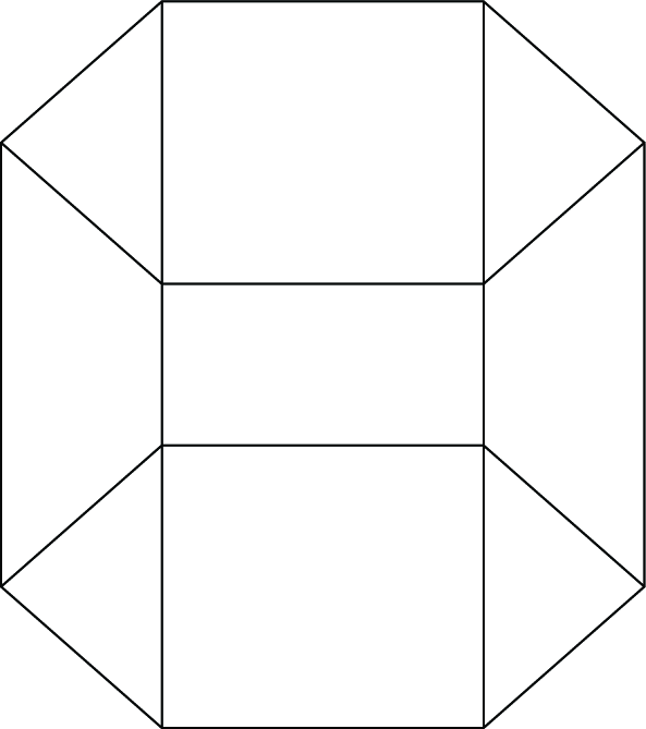
Joining two square pyramids together at their bases to form an octahedron and then cutting all six corners at one third of the edge length from each vertex create a truncated octahedron. The resulting truncated octahedron has edges of one third of the length of the octahedron edges. The geometry of the truncated octahedron and its top view of sectioned truncated octahedron, which is tessellated, are shown in the Figures 3 and 4, respectively. truncated octahedron is a polyhedron that has 14 faces. Out of these 14 faces, 8 are hexagon and 6 are square faces. The edges of the hexagon and square are of equal length.

Truncated Octahedron.

Top view of sectioned truncated octahedron after tessellation.
The truncated octahedron has 24 vertices and 36 edges. If the edge length of the truncated octahedron is

3.4. Edge Length Calculation
The distance between two opposite square faces of a truncated octahedron cell is

Fixing the edge length of the truncated octahedron.
From Figure 5, the transmission range R is calculated as

The edge length

To make all the nodes in the grid reachable to all the nodes in their neighboring cells, the upper bound of the edge length of the truncated octahedron is set as

3.5. Radius of Circumsphere
The diameter of the circumsphere which is the line joining the opposite vertex of the opposite hexagonal faces is shown in Figure 6.
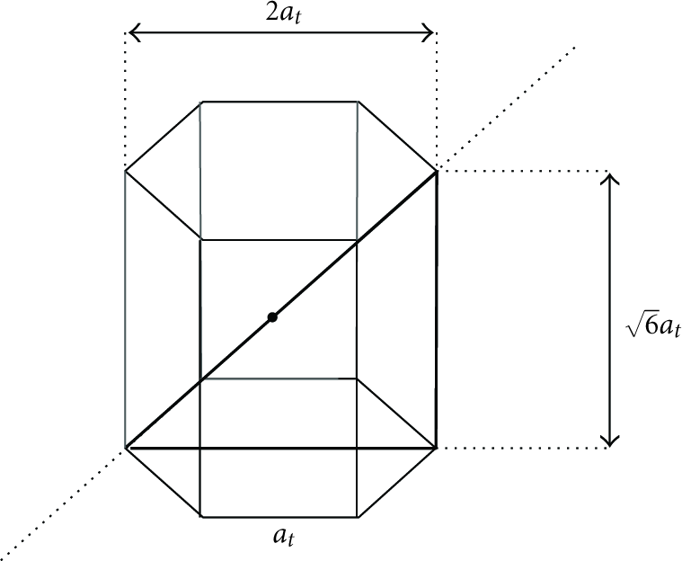
Radius of circumsphere of truncated octahedron.
The diameter circumsphere of the truncated octahedron is calculated as

The radius of circumsphere of the truncated octahedron is given by

The volumetric quotient of the truncated octahedron is given by

Substitute (5) and (10) in (11),

By simplifying (12), we get

The volumetric quotient value of the truncated octahedron is given by

The volumetric quotient of truncated octahedron is high compared with cube and hexagonal prism. This implies that the sensor field can be covered with less number of cells. truncated octahedron has more number of hexagonal faces than the square faces compared with other polyhedrons. Because of the above-mentioned reasons truncated octahedron is more suitable in three-dimensional sensor networks.
3.6. Proposed Model
Our proposed model with truncated octahedron cells for three-dimensional sensor networks is shown in Figure 7. We have assumed that all the nodes are having two radios. The sensor nodes are deployed in a uniformly random fashion over the 3D sensor field of size

Proposed model.
The 3D sensor field is divided into a number of truncated octahedron cells, and in each cell only one node is kept in active mode and all other nodes are kept in sleep mode. The node in active mode will act as a cell head and take part in the data-forwarding function. The responsibility of being a grid head is rotated among the nodes in the cell based on the available energy level. When the energy level of the cell head reduces below the threshold energy level, the responsibility of cell head is transferred to another node in the grid. In the simulation, we have set the threshold energy level to 25%. In order to balance the energy consumption of the nodes, the duty of the grid head is rotated among the other nodes in the grid based on the residual energy. Hence, the lifetime of the network is increased. Once all the nodes in the grid reach the threshold level, the same procedure is repeated till the entire energy is drained. During this time, it is suggested that the nodes in the grid may be replaced in order to ensure the strong connectivity in the network. When a node is forwarding the data packets, the choice of the next hop node is based on the direction in which the destination sink node is present. When Sparse Topology and Energy Management (STEM) scheme is integrated, the dual radio concept of STEM is implemented in all the nodes including the grid head.
The basic idea of STEM is to only turn on the sensing and some processing circuitries. The transceiver unit is kept in off state. When the sensor node detects an event, it will wake up its main processor to process the data in detail. It will wake up its radio when it is needed to transmit data to the sink. Now, the problem is that the radio of the next hop in the path to the data sink is still turned off. To overcome this problem, each node periodically turns on its radio for a short time to check whether any other node wants to communicate with it.
The node that wants to communicate is called initiator node, and the node it is trying to wake up is called target node. The initiator node wakes up its target node by sending a beacon. When the target node receives the beacon, it will send a response to the initiator node, and both nodes turn on their radio. Once both nodes have turned their radio on, a link is established between them and data packet is transferred. If that packet is intended for other node, the target node will act as the initiator node and send packet to the node in the next hop towards destination and the process is repeated.
In order to avoid the interference between the wake up beacon and the data packet transmission, transceiver uses dual radio, and each radio is operating at different frequency bands. The frequency band
3.7. Integration of STEM and GAF
GAF controls the number of active nodes to save energy without affecting the data-forwarding capacity. STEM saves energy by putting the radio of the sensor node into the sleep mode when they are not in use. The energy savings will be better when we combine the advantages of both schemes. For combining any two schemes, they have to be orthogonal to each other. STEM and GAF are orthogonal to each other and hence the resulting energy gain will be the full potential of both schemes.
In GAF, the sensor field is divided into number of virtual truncated octahedron cells and in each grid only one node is kept in active state. The node in active state will act as the grid head and take part in the data forwarding function. In the combined scheme, GAF manages one of the nodes in each cell as cell head based on its available energy. STEM controls cell head between the sleep mode and the active mode.
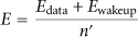
The energy consumption of a sensor node when there is no GAF is obtained as follows:

In GAF, only one node out of
The energy consumed by a node in GAF is obtained as follows:


4. Performance Evaluation
We verify our algorithm through simulations. We deploy N number of nodes in a uniformly random fashion over the 3D field of size

4.1. Simulation Setup
In our simulation we have chosen the transmission range
Radio characteristics.
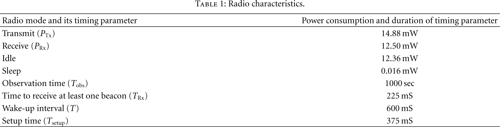
We divide the 3D field of size
Algorithm 1 explains the Hybrid topology management scheme using truncated octahedron cells in 3-dimensional sensor networks.
// Where Assigning the coordinates of a truncated octahedron
Finding cell ID of each node cell_i
//where cell_co
//where cell_co
//where
4.2. Simulation Results
The cell partitioning of the 3D network using cube-shaped cells is shown in Figure 8, where the sensor field is divided into number of cube-shaped cells.

3D network with cube cells.
Figure 9 shows the cell partitioning of the 3D network using Hexagonal-Prism-shaped cell, where the sensor field is divided into number of Hexagonal Prism-shaped cells.
3D network with HP cells.
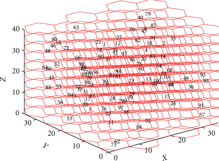
Figure 10 shows the cell partitioning of the 3D network using truncated-octahedron-shaped cell, Where the sensor field is divided into number of truncated-octahedron-shaped cells. The operational lifetime of the sensor network is improved by reducing the energy consumption of the sensor nodes. The topology management scheme is implemented by dividing the sensor field into number of cells. The size of the cells is fixed based on the radio transmission range. In each cell, one node is kept in active mode and all other nodes are in sleep mode. Since the size of the cells is set such that all the nodes in their first-tier neighboring cells can reach all the nodes in a cell, it is possible to perform data forwarding function with single node in each grid.

3D network with TO cells.
In sleep mode, the sensing and processing units are kept on and the radio unit is switched off. Whenever the sleeping node has data to send, it will turn on its radio unit. The active node in each cell will act as the cell head and take part in the data forwarding process.
Since all the nodes are having the same energy initially, so the grid head is selected randomly in each grid. In order to balance the energy consumption of the nodes, the duty of grid head is rotated among the nodes in the cell. Successively, grid head is selected based on the residual energy technique used in the HEED. Therefore, all the nodes in the grid will be getting the chance of grid head. In GAF, only one node out of
In cube cell, the average number of nodes per cell is 4 to 5; in the hexagonal prism, the average number of nodes per cell is 6 to 7; and in the truncated octahedron, the average number of nodes per cell is 9 to 10. Since all the nodes are having the same energy initially, grid head is selected randomly in each grid. Successively, grid head is selected based on the residual energy technique used in the HEED.
Even if every node in the grid participates in the grid head selection process, the maximum number of nodes within the grid is 9. Each and every grid is going to select its head independently, and hence this process will not take long time. The node which is not the grid head from the beginning still has got sufficient amount of energy to participate in the selection process and become a grid head.
Figure 11 shows the normalized energy consumption of the node in GAF using cube, hexagonal prism, and truncated octahedron cells. When the average number of sleeping nodes in the neighboring grid is 600, the normalized energy consumption of the sensor node is 0.31 for cube-shaped cells, 0.19 for Hexagonal Prism, and 0.15 for truncated-octahedron-shaped cell partitioning of the 3D sensor field. GAF using truncated octahedron cell consumes less energy than cube and Hexagonal Prism cells. Hence, we have taken the truncated octahedron cell for designing the Hybrid topology management scheme.

Energy comparison of a node in GAF using cube, HP, and TO cells.
Figure 12 shows the percentage of connectivity as the function of number of nodes deployed. The topology management scheme, which uses truncated octahedron partitioning, maintains full connectivity with less number of nodes. It is achieved because truncated octahedron has high volumetric quotient. This high volumetric quotient results in less number of grids and hence full connectivity is maintained with less number of active nodes.

Percentage connectivity versus nodes deployed.
Figure 13 shows that the number of active nodes required in the network to maintain full connectivity is minimized while partitioning the network using truncated octahedron cells. Since the number of active nodes required for maintaining the connectivity is less, the total energy consumed by the network is much less. Hence, the lifetime of the network is increased to a larger extent.

Number of active nodes required to maintain 100% connectivity.
Figure 14 shows the normalized energy consumption of the sensor node in the network under GAF, STEM, and Hybrid scheme using truncated-octahedron-shaped cell. In STEM, the energy consumption of the node is constant with respect to the average number of neighbors, because STEM works on the time domain.
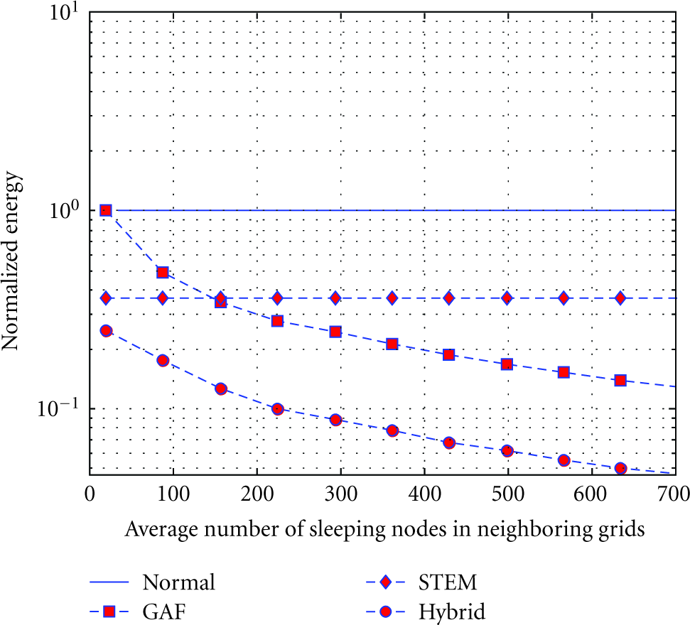
Energy consumption of a node in GAF, STEM, and Hybrid scheme using truncated octahedron cells.
The energy consumption of a node in GAF decreases with the average number of neighbors' increases, because the GAF algorithm is related to the density domain. When STEM is integrated with GAF, we got further reduction in the energy consumption of the sensor node. When the average number of sleeping nodes in the neighboring grids is 600, the normalized energy consumption of the sensor node is 0.15 for GAF using truncated-octahedron-shaped cell partitioning in 3D sensor field and the normalized energy consumption of the sensor node is 0.054 for Hybrid topology management scheme in 3D sensor networks.
Figure 15 shows the operation lifetime extension factor of the sensor node in GAF using truncated octahedron cells and in Hybrid topology management scheme. The operational lifetime of the sensor network is improved by 7 times in GAF using truncated-octahedron-shaped cells, and the operational lifetime is improved by 19 times in Hybrid topology management scheme when the average number of sleeping nodes in the neighboring grid is 600.

Lifetime improvement in GAF and Hybrid scheme using truncated octahedron cells.
5. Conclusion
In this paper, we have analyzed the GAF scheme using cube, Hexagonal-Prism, and Truncated-Octahedron shaped cells, and we have found that the truncated octahedron cell gives better performance than the Cube and Hexagonal-Prism shaped cells. GAF with truncated octahedron cells reduces the consumption of the node by 7 times when the average number of sleeping nodes in the neighboring grid is 600.
On the other hand, STEM reduces the energy consumption of the sensor node by switching its radio off when it is idle. In this work we simulate STEM with wake-up interval of 600 ms, which reduces the energy consumption of the node by a factor of about 2.5.
We have integrated STEM with GAF, and the Hybrid scheme reduces the energy consumption of the sensor node by 18 times in the three-dimensional sensor networks when the average number of sleeping nodes in the neighboring grid is 600. Hence, the Hybrid topology management scheme improves the lifetime of the sensor network by 19 times.