
Abstract
In deep drawing, a low blank holder force (BHF) can cause wrinkling, while a high BHF can lead to tearing. In this study, a variable blank holder force (VBHF) approach to deep drawing is employed, and a simple closed-loop type algorithm is developed for the VBHF trajectory. The proposed algorithm is divided into two phases. The objective of the first phase is to check wrinkling and tearing. In this phase, a low BHF is used as the initial BHF, which is then increased to prevent wrinkling while controlling tearing. This phase of the algorithm is terminated when tearing occurs. In numerical simulation, the distance between the die and the blank holder is used to measure wrinkling, and the minimum thickness of the blank is used to determine the tearing. In the second phase of the algorithm, the deviations in thickness of the part are iteratively examined, without neglecting the occurrence of wrinkling. One of the advantages of using VBHF instead of constant BHF is that it reduces the forming energy. The validity of the proposed algorithm is examined comparing numerical simulation and experimental results. Finally, the proposed algorithm is also applied to obtain the segmented VBHF trajectory.
1. Introduction
Computer Aided Engineering (CAE) is now widely used in industry. Physical phenomena can be easily understood using CAE. CAE, including optimization techniques, is also widely applied to sheet forming [1]. In sheet forming, there are many factors that affect the quality of products, such as the Blank Holder Force (BHF), the friction and lubrication conditions of the interface, and the die geometry. Among these factors, BHF plays a key role in the flow of material. In most cases, a constant BHF is applied over the punch stroke. A lower BHF will cause wrinkling due to excessive material flow into the die. In order to prevent wrinkling, a higher BHF needs to be applied. However, a higher BHF can lead to tearing due to insufficient material flow. Thus, it is important to determine the appropriate constant BHF over the punch stroke. Wang et al. [2] suggested that there are four basic windows for BHF formability, determined using constant BHF, as shown in Figure 1. These formability windows represent the relationship between the BHF and the punch stroke.
Four basic BHF formability windows.

In the formability windows shown in Figure 1(a), it is possible to form a sheet without wrinkling and tearing by applying an appropriate constant BHF, whatever the forming depth of the part. However, in other cases the forming depth is limited when applying a constant BHF. In the formability windows shown in Figures 1(b) and 1(c), particularly, the advantages of a Variable Blank Holder Force (VBHF) approach, in which the BHF varies throughout the stroke, are evident. Numerous researches have been conducted on the VBHF trajectory. They can be roughly classified into two categories: those based on a closed-loop type algorithm and those based on the Response Surface Methodology (RSM). Let us briefly review the use of a closed-loop type algorithm to determine the VBHF trajectory. Wang et al. [2] and Lin et al. [3] developed a closed-loop type algorithm for determining the VBHF trajectory in which a proportional-integral-derivative (PID) controller is introduced. This PID controller was applied to an example with six separate binders, so that six VBHF trajectories could be obtained. Sheng et al. [4] developed a closed-loop type algorithm that included a PI controller; they compared their results with those obtained by Cao and Boyce [5]. Lo and Yang [6] also utilized a PID controller to determine the VBHF trajectory. This PI controller algorithm is designed to regulate the BHF to the minimum required levels, just enough for suppressing wrinkling conditions, corresponding to each time control step over the entire punch stroke. Sheng et al. [4] and Lo and Yang [6] utilized maximum part thinning and flange wrinkling as the state variables. Cao and Boyce utilized flange wrinkling and deformed strain instead of maximum part thinning. With these values as state variables, PI controller algorithm is used to adjust the BHF. It is considered that Hardt and Fenn [7] and Sim and Boyce [8] provided the basic idea for this avenue of research. Sim and Boyce [8] applied the method introduced in the work of Hardt and Fenn [7] to deep drawing process simulation. Other similar researches using a closed-loop type algorithm can be found in [9, 10]. The validity of each of these research efforts has been examined through numerical simulation and experiment. In these research efforts, the technique that is employed to measure wrinkling and tearing is an important issue for numerical simulation. Thus, wrinkling is measured by the distance between the die and the blank holder. Wrinkling will develop when the distance between them goes beyond a critical value. In this case, the BHF is increased to suppress wrinkling. Tearing, on the other hand, is measured by the reduction in the thickness. This measuring technique is useful for the numerical simulation.
The other approach for determining the VBHF trajectory is the use of Response Surface Methodology (RSM), which is an approximation technique. Most of the research using RSM utilizes the Forming Limit Diagram (FLD). In general, two objective functions to prevent wrinkling and tearing are defined using the FLD, which are transformed into one by the weighted sum. The BHF is considered as the design variables and some values are tested. Then, the objective function obtained by the weighted sum is minimized to find the optimal BHF. Su et al. [11] developed the Adaptive Response Surface Methodology (ARSM) to determine the optimal spatial VBHF and have applied it to rectangular box deep drawing. Jakumeit et al. [12] defined four objective functions (1) to prevent tearing (2) to prevent wrinkling (3) to guarantee the blank stretching without excessive thinning; and (4) to minimize the springback effect. They employed the Kriging to approximate the objective functions and determined the VBHF trajectory. Wei and Yuying [13] also defined four objective functions (1) to prevent tearing (2) to prevent wrinkling (3) to minimize stretching and (4) to minimize thickness deviation. Using this approach, they determined the optimal spatial VBHF. Similar researches can be found in [14–19].
Other approaches for determining the VBHF trajectory, which employ the Neural Network and ARMA, can be found in [20, 21]. The VBHF approach can also be applied to the reduction of springback [22].
Here, we briefly summarize the advantages and disadvantages of both approaches. A closed-loop type algorithm is easy to implement with Finite Element Analysis (FEA) code. In addition, the detailed VBHF trajectory can be obtained. One of the difficulties for determining the VBHF trajectory with a closed-loop type algorithm is to develop the algorithm. In the past researches, in order to avoid wrinkling and tearing, local quantity such as the distance between the die and blank holder was widely employed in the numerical simulation. These researches did not consider any global quantity evaluated for the blank throughout the forming process. Following previous results obtained with RSM approaches, it is preferable to incorporate the global quantity of the blank throughout the forming process. In RSM approaches, multiobjective optimization problem is formulated by using the FLD. To determine the VBHF trajectory by RSM approaches, BHFs and the strokesteps are taken as the design variables. Thus, when one wishes to determine a detailed VBHF trajectory by RSM approaches, the number of design variables strongly increases, leading to large-scale optimization problems. In general, it is difficult to solve the large-scale optimization problems. Therefore, in RSM approaches only a few strokesteps are taken as the design variables. These result in a rough VBHF trajectory in comparison with the one obtained with closed-loop type algorithms.
In this paper, a simple closed-loop type algorithm is developed for determining the VBHF trajectory. This algorithm is roughly divided into two phases. The objective of the first phase of the algorithm is to prevent wrinkling. A lower BHF is employed at start and then it is gradually increased to suppress wrinkling. In the first phase, a higher BHF can be attained that might cause tearing. This is why the second phase is introduced. The objective of the second phase is to reduce the BHF by considering the thickness deviation of the blank. By reducing the BHF attained in the first phase, the risk of tearing is reduced. Nevertheless, in the second phase, the risk of wrinkling is constantly checked due to the BHF reduction. The characteristics of the proposed algorithm can be summarized as follows.
The proposed algorithm is very simple and is easy to implement.
Both local and global quantities are employed in the proposed algorithm. Therefore, the distance between the die and the blank holder and the minimum thickness of the part were used as the local quantities. In addition, the thickness deviation throughout the forming process is also employed as the global quantity.
The proposed algorithm is applied to a square cup deep drawing. LS-DYNA, which is a dynamic explicit FEA code, is employed in the numerical simulation. In order to examine the validity of the proposed algorithm, an experiment was conducted using a hybrid AC servo press, belonging to the KOMATSU Industries Corp. In addition, the proposed algorithm is applied to determine the variable blank holder force trajectory for a segmented binder. The validity of the segmented variable blank holder force trajectory is also examined through numerical simulation results.
The remainder of this paper is organized as follows: in Section 2, the finite element models are briefly described. In addition, some conditions regarding the evaluation of wrinkling, tearing, and thickness deviation are also described. In Section 3, the VBHF algorithm is presented. The results of numerical simulation obtained by the proposed algorithm are presented in Section 4. In Section 5, experimental results are presented and compared with the ones obtained through numerical simulation. Finally, the proposed algorithm is applied to determine the VBHF trajectory for a segmented binder.
2. FEA Models and Some Conditions in the Numerical Simulation
2.1. Finite Element Models and Material Properties
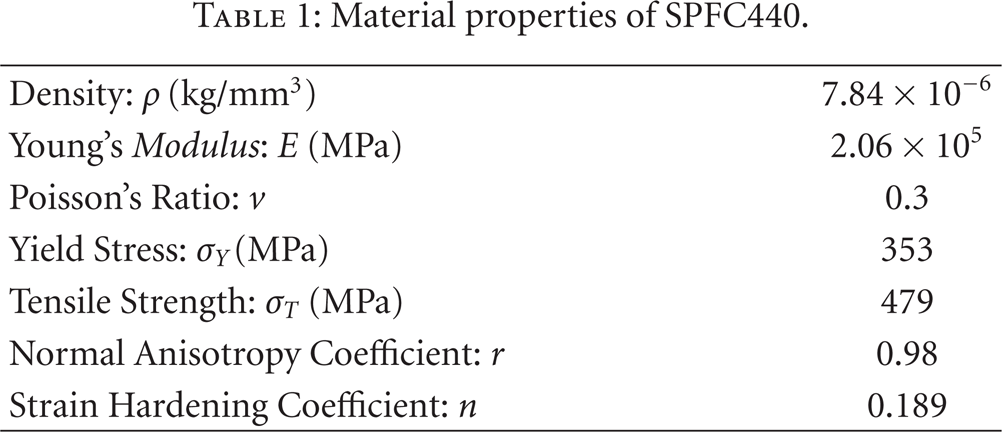
In order to optimize VBHF trajectory based on FEA, it is essential to validate the FE model. Thus, an experimental test was performed with a constant BHF (=100 (kN)). SPFC440 (Steel Plate Formability Cold) was selected as the test material for which the material properties are shown in Table 1. The material properties shown in Table 1 are obtained through the experiment. The stress-strain relationship is defined as follows:

The blank size is 185 (mm)
Material properties of SPFC440.
(a) Formed part obtained in the experiment performed with a constant BHF of 100 (kN), (b) Dimensions of molding.

All numerical simulations are performed with LS-DYNA. Considering the geometrical and material symmetry, 1/4 model is employed in the numerical simulation, as shown in Figure 3. Thus, a blank size of 92.5 (mm)
Element type and number of finite elements.

Finite element models.

2.2. Motion Setting
As shown in Figure 3, the punch is fixed and the BHF is applied in the positive z-direction. The counter punch and the die drop to the negative z-direction. At the bottom dead center, the counter punch, the die, and the blank holder move upwards. The motions of these three items in the experiment are shown in Figure 4. In the numerical simulation, the same data was employed. The initial velocity is vinit = 267 (mm/s), and the maximum velocity is v max = 2059 (mm/s).

Motion of the die, blank holder, and counter punch.
2.3. Finite Element Model Validation
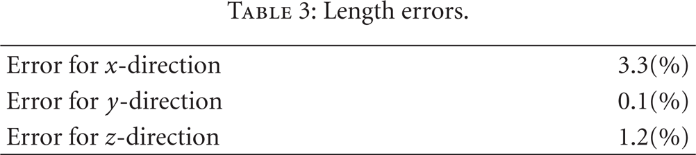
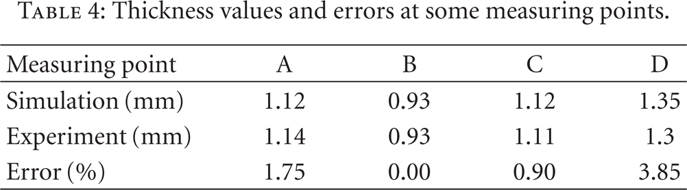
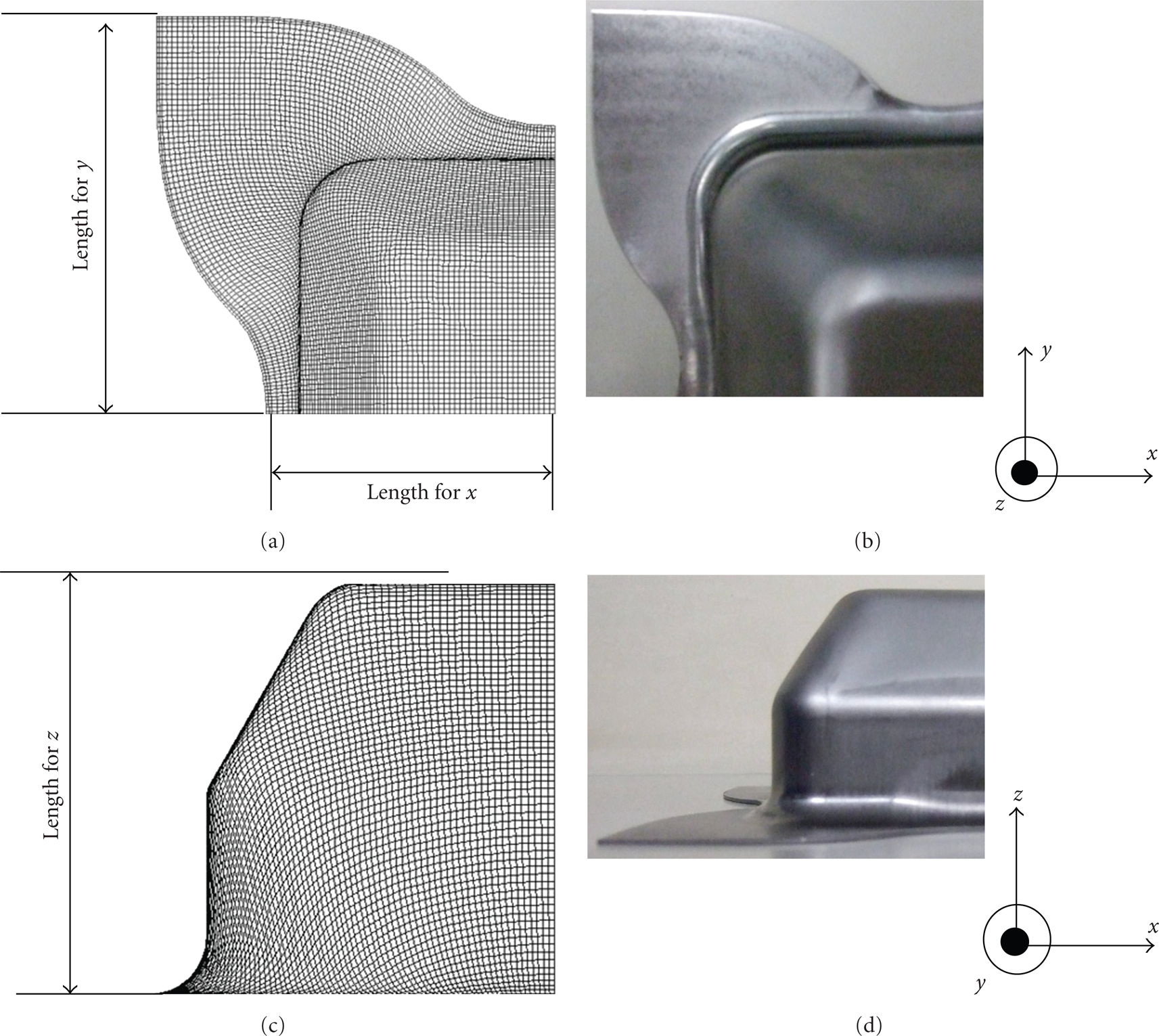
A numerical simulation was carried out to examine the validity of the FE model and selected conditions. A constant BHF (=100 (kN)) was applied. Comparative results of the numerical simulation and experiment are shown in Figure 5. The errors in the length are also shown in Table 3. In addition, the thickness at some points, shown in Figure 6, was measured. Errors of the thickness at measuring points are also listed in Table 4. These results validate the FE model and selected conditions.
Length errors.
Thickness values and errors at some measuring points.
Comparison of the numerical simulation and the experiment.
Measuring points of the thickness.

2.4. Wrinkling Condition
A test was performed, both experimentally and numerically, using a constant BHF equal to 20 (kN). Wrinkling in the numerical simulation and in the experimental test is shown in Figures 7 and 8, respectively.

Wrinkling predicted in the numerical simulation performed with a constant BHF of 20 (kN).
Wrinkling predicted in the experimental test performed with a constant BHF of 20 (kN).
Figure 7 shows that the distance D between the die and the blank holder is much larger than the initial thickness t0 when wrinkling occurs. Thus, in order to suppress wrinkling, the BHF should be increased. According to past researches [2–4], the following condition is adopted in order to measure the wrinkling:

where
2.5. Tearing Condition
Tearing occurs when the thickness is smaller than a critical value, tcri [4]. However, this condition needs to be verified for all the finite elements in the blank. If at least for one element the condition is fulfilled, then tearing occurs. Thus, the tearing condition is given as follows:

where m denotes the number of finite elements in the blank and ti represents the thickness of the ith finite element.
2.6. Thickness Deviation
In numerical simulation, wrinkling and tearing conditions can be regarded as the local quantities. Wrinkling is measured by the distance between the die and the blank holder, and tearing is determined by the maximum thinning. In this paper the thickness deviation is taken as global quantity. The thickness deviation can evaluate the whole condition of the blank throughout the forming process. The thickness deviation T is defined as follows:

where t i represents the thickness of the ith element, t0 denotes the initial thickness, and p is the deviation parameter. In the RSM approach, (4) is often employed [13, 15–17]. In this paper, p is equal to 2 [16].
3. A Closed-Loop Type Algorithm for the VBHF Trajectory Considering the Thickness Deviation
3.1. A Closed-Loop Type Algorithm
In this section, a simple closed-loop type algorithm for determining the VBHF trajectory is explained. The algorithm for determining the VBHF trajectory is shown in Figure 9.

A closed-loop type algorithm for determining the VBHF trajectory.
The proposed algorithm is roughly divided into two phases. The aim of the first phase is to prevent wrinkling and tearing (the part inside the dashed-line rectangle in Figure 9). The aim of the second phase is to consider the thickness deviation (the part inside the solid-line rectangle in Figure 9). For the sake of simplicity, the first phase is called the wrinkling phase, and the second phase is called the thickness deviation phase. Total stroke L
max
is partitioned into n strokes, such that

where α is the coefficient to increase the BHF. In this phase, no wrinkling can be observed. In the wrinkling phase, local quantity (the distance between the die and the blank holder) is employed in order to measure the wrinkling. In this phase, when the tearing conditions expressed by (3) are satisfied, the algorithm is terminated. As soon as both conditions are satisfied for the ith stroke, the algorithm advances to the thickness deviation phase.
The aim of this next phase is to examine the thickness deviation of the blank. To this end, global quantity is considered such that when T is less than M, which is the critical value in the thickness deviation, the BHF for the ith stroke is determined. Otherwise, the BHF is iteratively decreased as follows

where β is the coefficient to decrease the BHF. Although the BHF decrease will lead to wrinkling, the development of wrinkling is constantly checked in this phase (

An illustrative example of VBHF.
In Figure 10, the wrinkling phase is analyzed for the
3.2. Parameters in the Algorithm
The proposed algorithm, shown in Figure 9, requires five parameters: (1) α; the coefficient to increase the BHF, (2) β; the coefficient to decrease the BHF, (3)
4. Numerical Simulation
The validity of the proposed algorithm is examined through numerical simulation. The parameters of the algorithm adopted in the selected example are listed in Table 5.
Parameter settings.

The total length of stroke L max is 62 (mm), which was partitioned into 125 strokes. Based on Obermeyer and Majlessis [23] suggestion that is important in sheet forming to use minimum BHF, the lower BHF of 20 (kN) is taken as the initial BHF.
4.1. Initial Blank Holder Force = 20 (kN)
The initial BHF is set to 20 (kN), which causes wrinkling, as described in Section 2.4. The algorithm is applied to the SPFC440 material. The VBHF trajectory obtained is shown in Figure 11, and the final formed part obtained with the VBHF trajectory is shown in Figure 12.

VBHF trajectory at initial BHF = 20 (kN).

Final formed part obtained in the simulation with the VBHF.
The minimum thickness value of t min (=0.97) is observed at the punch corner. This minimum value is greater than tcri(=0.90). Thus, Figure 12 shows that no wrinkling or tearing is observed with the proposed algorithm.
The gray area in Figure 11 is considered to represent the approximated forming energy. Strictly, the punch force should be employed to calculate the forming energy. However, it is difficult to calculate the punch force in experiment, and then we consider that the gray area represents the approximated forming energy. In order to compare the approximated forming energy with the VBHF trajectory, two constants values for BHF are also considered. One is BHF = 75.2 (kN), which is the maximum BHF with the VBHF trajectory. The other is BHF = 100 (kN), a setting at which no wrinkling or tearing can be observed, as shown in Figure 2(a). The values obtained for the approximated forming energy are listed in Table 6.
Comparison of approximated forming energy.

It is apparent from Table 6 that the VBHF can drastically reduce the approximated forming energy, as compared to a constant BHF.
4.2. Parameter M and VBHF Trajectory
The parameter M, which is the critical value in the thickness deviation, affects the VBHF trajectory. If a large value is assigned to the parameter M, the second phase of the algorithm will be skipped. In this case, the BHF will be increased as the stroke proceeds, and a higher BHF will be attained, which can cause tearing. Therefore, a smaller M value is recommended. In this section, different critical values of M are used in order to qualitatively examine their effect upon the VBHF trajectory. Three critical values are used: M= 2.0, M = 2.5, and M = 3.0. The VBHF trajectories for each critical value are shown in Figure 13.

VBHF trajectories for three critical values M.
It is qualitatively clear from Figure 13 that similar VBHF trajectories can be obtained. The BHF is increased as the punch stroke proceeds, and the BHF is decreased in the final stage of the punch stroke. Therefore, taking into account the forming energy associated to each BHF evolution, the critical value for M can be estimated through numerical simulations, since there are no guidelines for determining M in advance.
5. Experiment
In this section, the validity of the proposed algorithm is examined through an experiment test. The VBHF trajectory was obtained through a numerical simulation, and the experiment was conducted based on this VBHF trajectory. A servo press H1F was used in the experiment, which is a hybrid AC servo press belonging to the KOMATSU Industries Corp. SPFC440, whose material properties were presented in Table 1, it was used as the blank.
5.1. Initial Blank Holder Force = 20 (kN)
The VBHF trajectory used in the experiment is shown in Figure 14 (solid line) and compared with the VBHF trajectory obtained in the numerical simulation (dashed line).

Comparison between the VBHF trajectory in numerical (solid line) and in experimental (dashed line) test.
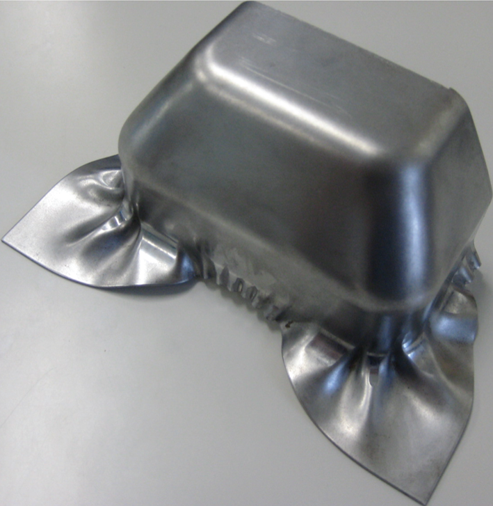
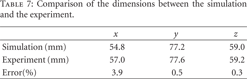
The final result of the experiment is shown in Figure 15. The critical dimensions identified in Figure 5 are summarized in Table 7. In addition, the thickness at some points, shown in Figure 6, at which tearing often occurs, was measured and the results obtained in the numerical simulation and the experiment are listed in Table 8.
Comparison of the dimensions between the simulation and the experiment.
Comparison of the thickness between simulation and the experiment.


The square cup deep drawing in the experiment (Initial BHF = 20 (kN)).
It is clear from Figure 15 that no wrinkling or tearing can be observed in the physical results obtained in the experiment. A high degree of accuracy in regard to dimensions and thickness was also obtained.
6. Segmented Variable Blank Holder Force Trajectory
In this section, we consider the segmented Variable Blank Holder Force (segmented VBHF) trajectory [2, 3]. It is very difficult to conduct the experiment of the segmented VBHF trajectory, and then only numerical simulation is performed. Several researches on the segmented variable blank holder force have been reported [11, 13, 14, 16]. In these researches, the area of the blank holder is segmented, and a constant BHF of each of the segmented areas is determined. The BHFs of each segmented area are not varied throughout the punch stroke. In the following example, a VBHF trajectory will be determined for each segmented blank holder area.
The FE model shown in Figure 16 is used to determine the segmented VBHF trajectory, where the blank holder of the FE model is segmented. Due to symmetry conditions, two VBHF trajectories (VBHF1, VBHF2) are considered in the numerical simulation, in order to determine VBHF trajectories.

Finite element model for segmented VBHF.
The proposed algorithm is applied to determine both segmented VBHF trajectories. Therefore, the proposed algorithm is applied simultaneously to both BHF. Initial BHFs (BHF1, and BHF2 in Figure 16) are set to 12 (kN), and the parameter M, which is the critical value in the thickness deviation, is set to 2.5. The segmented VBHF trajectories (VBHF1, VBHF2) are shown in Figure 17.

Segmented VBHF trajectories.
The maximum BHF of VBHF1 is 44.4 (kN), and the maximum BHF of VBHF2 is 12.0 (kN). It is clear from Figure 17 that the maximum value of VBHF1 is greater than that of VBHF2. In general, tearing can be observed at the corner part. It is expected, from the result of Section 5, that tearing will occur at point B in Figure 6. In order to avoid tearing, it is preferable that VBHF2 is smaller than VBHF1 through the punch stroke. In addition, the trajectory of VBHF2 can be roughly approximated by the constant BHF in comparison with the one of VBHF1. This result implies that the effect of VBHF1 is greater than the one of VBHF2. It is apparent from Figure 17 that this can be achieved by applying the proposed algorithm. The thickness values obtained at the measuring points shown in Figure 6 are listed in Table 9, for the segmented VBHF trajectories.
Thickness at the corner points.
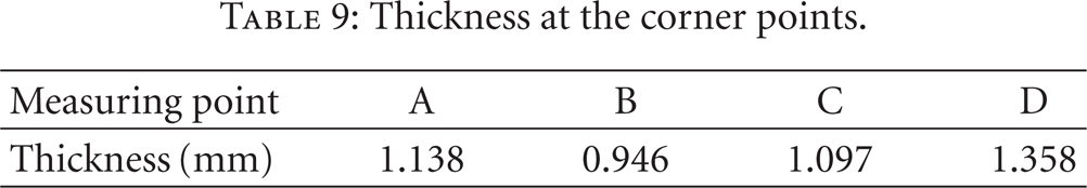
It is clear from Table 8 that no tearing or wrinkling can be observed by applying the proposed algorithm to the segmented VBHF trajectory.
7. Conclusions
In this paper, a simple closed-loop type algorithm for the VBHF trajectory was developed, and it was applied to a square cup deep drawing. The proposed algorithm can be roughly divided into two phases: the wrinkling phase and the thickness deviation phase. In the wrinkling phase, the BHF is increased in order to suppress wrinkling. In the thickness deviation phase, the BHF is decreased. The proposed algorithm begins with a low BHF. This is in conformance with the suggestion of Obermeyer and Majlessi [23] regarding the importance of sheet forming by using minimum BHF. An FE model was constructed on basis of the experiment. Numerical simulation was carried out in order to examine the validity of the proposed algorithm. Through the numerical simulation, it was found that the approximated forming energy achieved with the VBHF could be reduced drastically, as compared to the application of a constant BHF. The validity of the proposed algorithm was evaluated through numerical examples. In addition, the proposed algorithm was applied to determine the segmented VBHF trajectory.