
Abstract
We present a kinematic design of a translational parallel manipulator with fine adjustment capability of platform orientation. In order to clarify possible kinematic structures for it, structural synthesis of fully decoupled mechanism and partially decoupled mechanism both with six degrees of freedom (dof) was carried out based on the synthesis results of translational and rotational parallel mechanisms with three dof. All possible kinematic structures were obtained. Of these, one partially decoupled mechanism was selected and a kinematic design of a prototype manipulator was done. Its characteristics in terms of workspace, singularity, orientation adjustment capability, and coupling characteristics between translational and rotational displacement were discussed with experimental results regarding fine adjustment capability of platform orientation.
1. Introduction
A parallel manipulator that has three degrees of freedom (dof) and outputs translational motion without changing its orientation is called a “translational parallel manipulator.” A translational parallel manipulator has potential for use in assembly, machining, and coordinate measurements. The manipulator is composed of a base, platform, and multiple connecting chains arranged in parallel between the base and platform.
Many researchers in recent years have shown interest in translational parallel manipulators and mechanisms. The kinematic conditions for the connecting chain to obtain translational motion of the platform have been investigated [1, 2]. Various kinematic structures for translational parallel manipulators have also been investigated [3, 4]. Further, optimization taking into consideration the manipulator's workspace has been done [5–7]. Translational parallel mechanisms have been applied to medical robots [8] and micromanipulators [9].
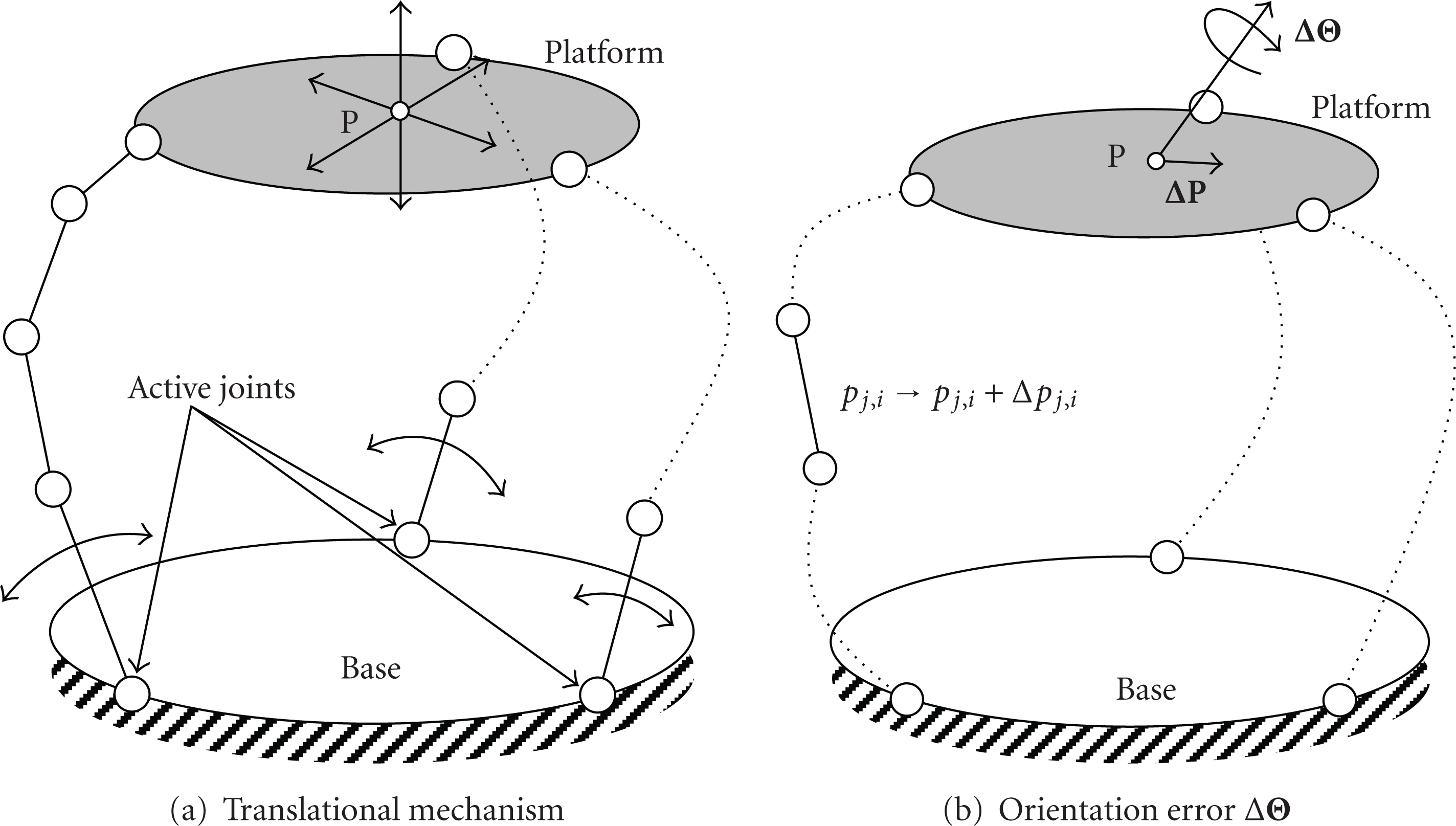
The errors in the output pose of a manipulator caused by dimensional errors, such as these in links, can be classified into two groups. The first group contains errors that can be compensated for by calibration or full closed-loop control. Such errors are called “compensatable errors” [10, 11]. The tolerance requirements with respect to these compensatable errors depend on calibration or the performance of the controller, and these are not usually severe. The second group contains errors that cannot be compensated for by any means, either during or prior to manipulation. Such errors are called “uncompensatable errors” [10, 11]. They depend on kinematic structures and parameters and tolerances. In designing and controlling a lower-dof parallel manipulator, such as a translational parallel manipulator, engineers must take uncompensatable error into consideration. For example, if there is a dimensional error in a link of a connecting chain of a translational parallel manipulator, the platform changes its orientation according to motion (Figure 1), and this orientation error cannot be compensated for by the input of active joints. One approach to this is to minimize uncompensatable error by determining the optimal values of kinematic constants at the design stage [11], taking tolerances into account. Another approach is to change the structure of the mechanism so that fine adjustments can be added to the output motion to eliminate the uncompensatable error.
Translational parallel mechanism and its orientation error.
Taking the uncompensatable error of a translational parallel manipulator into consideration, a spatial parallel mechanism with six dof, such as a Stewart platform, can be considered as an alternative mechanism to it. However, it needs six actuators of the same capacity in operation throughout the motion though the main output motion requires three dof. Such a composition of a mechanism is inefficient from the view point of facility and energy. In order to solve such a problem, while the uncompensatable error can be compensated, a concept of mechanism structure, which has three actuators to generate the translational motion as the main output motion and three actuators to compensate for the orientation error, is proposed. Since three actuators for compensating for orientation error operate only when accurate output orientation is required, they consume less energy than the actuators do in a spatial parallel mechanism with six dof. And, since displacement and power required to these actuators for compensating for orientation error are relatively small, they can be compact, light, and inexpensive. In the present paper, following this concept, kinematic design of a translational parallel manipulator with fine adjustment capability of platform orientation (TPMFAO) is discussed. Section 2 describes the basic concept underlying the structural synthesis of TPMFAO. Sections 3 and 4 briefly review the kinematic structures for translational and rotational parallel manipulators with three dof. Section 5 discusses the derivations for the kinematic structures of TPMFAO. Section 6 discusses the design of a prototype TPMFAO and its orientation adjustment capability with theoretical and experimental results. Section 7 summarizes the conclusions.
2. Basic Concept for Structural Synthesis of Translational Parallel Manipulator with Fine Adjustment Capability of Platform Orientation
2.1. Condition of Mechanism Structure
A manipulator must have six degrees of freedom (dof) to achieve fine adjustments of the platform orientation with gross translational motion. We considered the following conditions in the structural synthesis of TPMFAO for its real applications.
It has three connecting chains.
Each connecting chain has the same structure. The joints in a connecting chain are numbered 1, 2, …, 6 from the base.
Revolute and prismatic joints are used to compose a connecting chain. Other joints such as a cylindrical joint are constructed by combining revolute and prismatic joints.
Each connecting chain has two active joints. One active joint is to correspond to the translational motion, as the main output motion, of the platform. These active joints are called main active joints. The other active joint in each connecting chain is to generate rotational motion of the platform. These joints are used to make fine adjustments to the platform's orientation. These joints are called subactive joints.
The main active joints are located at the first or second joints, while any location for the subactive joints is acceptable.
Since actuators are heavy compared with links and joints, it is better to locate active joints as close to the base as possible. Since subactive joints may be constructed compact and light due to their small displacement and power, condition (5) was taken into account in our study.
If the motion of the platform generated by the subactive joints is pure rotational motion around a specific point on the platform, this mechanism is called a “fully decoupled mechanism.” If this motion is rotational motion with coupled translational motion, this mechanism is called a “partially decoupled mechanism.” These mechanisms are considered as the candidates for TPMFAO.
We can find many studies [12–19] on fully and partially decoupled parallel manipulators and mechanisms. Structural synthesis of partially decoupled parallel mechanism with six connecting chains has been done [18]. A procedure of structural synthesis of fully decoupled parallel manipulator, in which three connecting chains are used and active joints are located at only the first and second joints, has been presented and a kinematic design of a fully decoupled manipulator has been discussed [19]. Even though these studies were helpful in our study, all possible kinematic structures that satisfy the five conditions have not yet been clarified.
2.2. Fully Decoupled Mechanism
The main active joints in a fully decoupled mechanism generate translational motion of the platform while subactive joints generate pure rotational motion around a specific point on the platform (Figure 2). Then, the relationship between infinitesimal input displacement (

Fully decoupled parallel mechanism.
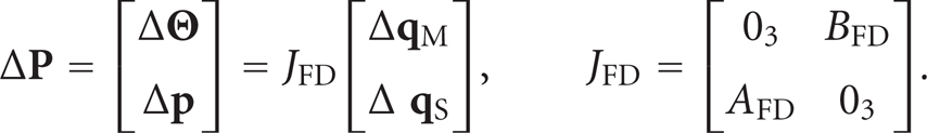
Here, JFD is the 6 × 6 Jacobian matrix, AFD and BFD are 3 × 3 matrices, and
2.3. Partially Decoupled Mechanism
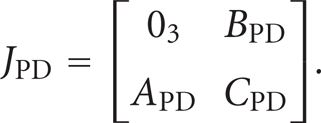
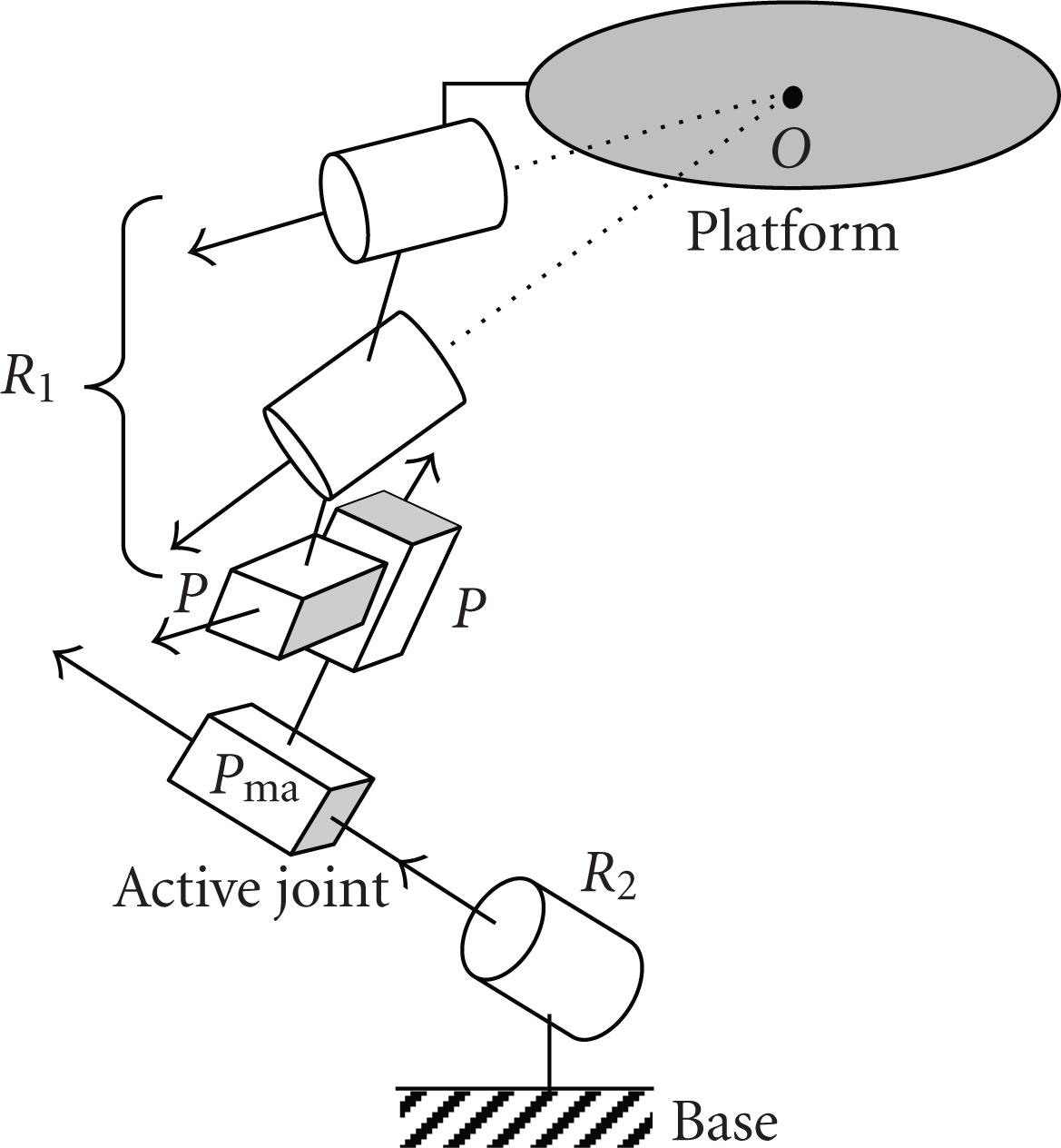
The main active joints in a partially decoupled mechanism generate translational motion of the platform while subactive joints generate rotational motion with coupled translational motion (Figure 3). Then, the Jacobian matrix of a partially decoupled mechanism at any platform pose can be written in the following form:

Partially decoupled parallel mechanism.
In the above discussions on the characteristics of fully and partially decoupled mechanisms, the first-order derivatives of the relationship between the input and output displacements were used. Though such a first-order approximation of the displacement characteristics is effective to clarify the motion characteristics of a mechanism, there exist small errors between the displacements obtained by the first-order model and the real mechanism due to the effect of the second-order and higher-order terms. Therefore, in order to eliminate the uncompensatable error of a lower-dof mechanism, iterative compensation should be applied if the first-order model is used.
3. Structures for Translational Parallel Mechanism
The structures for translational parallel mechanism with three dof are shown taking into consideration the conditions for TPMFAO. Referring to a previous study [2], the structures for translational parallel mechanism with three connecting chains, each with five single-dof joints, are listed in Table 1. R and P correspond to revolute and prismatic joints. In these mechanisms, all revolute joints belong to either of two groups. Revolute-joint axes belonging to the same group have the same direction. To represent the group of revolute joints with their axes in the same direction, dots and bars are used as
Kinematic structures for translational parallel mechanism.


4. Structures for Rotational Parallel Mechanism
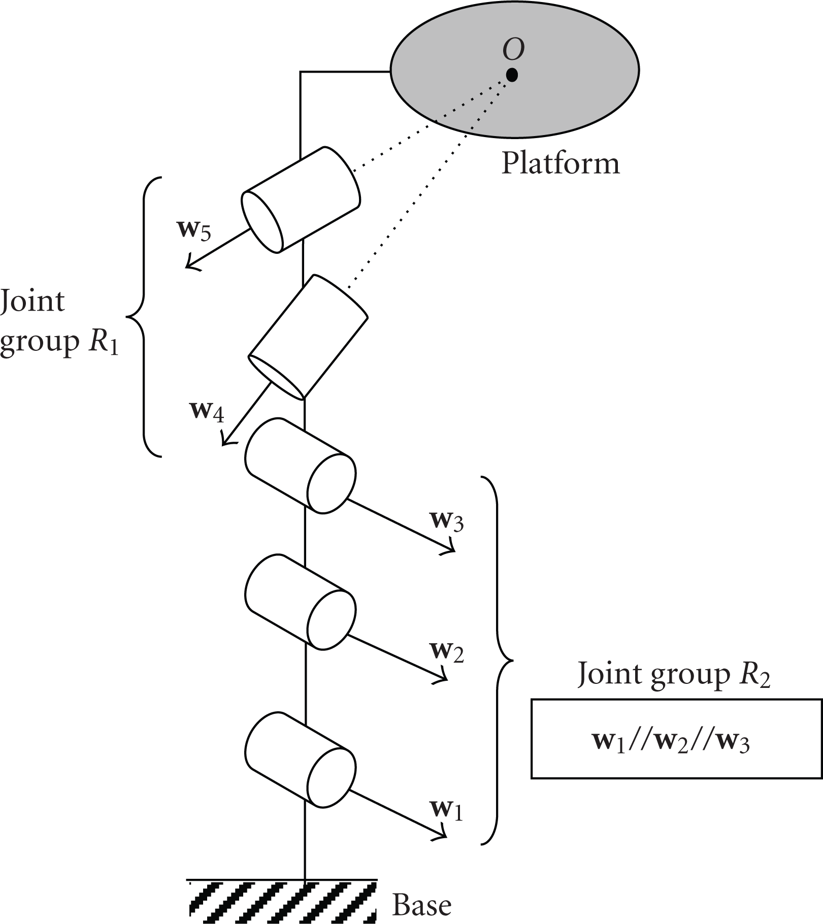
The structures for pure rotational parallel mechanism with three dof are shown in this section. Referring to previous studies [20, 21], the structures for pure rotational parallel mechanism with three connecting chains, each with five single-dof joints, are listed in Table 2. In these mechanisms, all revolute joints belong to either of two groups. The axes of the revolute joints belonging to the first group pass through the center of rotation of the platform. The axes of the other revolute joints belonging to the second group are parallel and do not pass through the center of rotation. R1 and R2 are used to represent the joint groups of the revolute joints(R1: the first group; R2: the second group). And, the axes of the prismatic joints are perpendicular to those of the revolute joints in the second group. An example of connecting chain is shown in Figure 5, in which the revolute joint belonging to the second group connects with the base.
Kinematic structures for pure rotational parallel mechanism.

5. Structural Synthesis of Translational Parallel Manipulator with Fine Adjustment of Platform Orientation
This section discusses the kinematic structures for fully and partially decoupled mechanisms for TPMFAO that can be derived from the kinematic structures of translational and pure rotational parallel mechanisms presented in the preceding sections.
5.1. Fully Decoupled Mechanism
The kinematic structures of fully decoupled mechanism can be clarified by adding a revolute or prismatic joint to the mechanisms listed in Tables 1 and 2. To accomplish fully decoupled motion, each connecting chain should become
a chain for a translational parallel mechanism when the subactive joints are locked at any position,
a chain for a pure rotational parallel mechanism when the main active joints are locked at any position.
The conditions for a chain to generate translational motion and pure rotational motion are as follows.
Conditions for generating translational motion.
Number of joints in a connecting chain is five. The axis directions of revolute joints are two. Number of revolute joints of the same axis direction is fewer than four. Number of prismatic joints is fewer than four.
Conditions for generating pure rotational motion.
All revolute joints belong to either of two groups mentioned in Section 4. Number of revolute joints belonging to a group is fewer than four. Number of revolute joints belonging to the first group is more than one. Prismatic joints are perpendicular to the revolute joints belonging to the second group. Number of prismatic joints is fewer than three.
The kinematic structures that satisfy these conditions are listed in Table 3. Here, a joint with subscript “ma” represents a joint that must be a main active joint, and a joint with subscript “sa” represents a joint that must be a subactive joint. The prismatic joints denoted by
Kinematic structures for fully decoupled mechanism.

The additional prismatic joint must be the main active joint.
In the case where there are more than one revolute joints belonging to the second group (R2) in a connecting chain, they must passively move according to the motion of the prismatic joints used as the main active joints (
An
5.2. Partially Decoupled Mechanism
The structures for partially decoupled mechanism can be derived by adding a joint to those of translational parallel mechanism listed in Table 1 so that the following conditions are satisfied.
The conditions for translational parallel mechanism still hold even when an additional joint is at any position.
Only a revolute joint is added to the connecting chain to enable the platform to rotate.
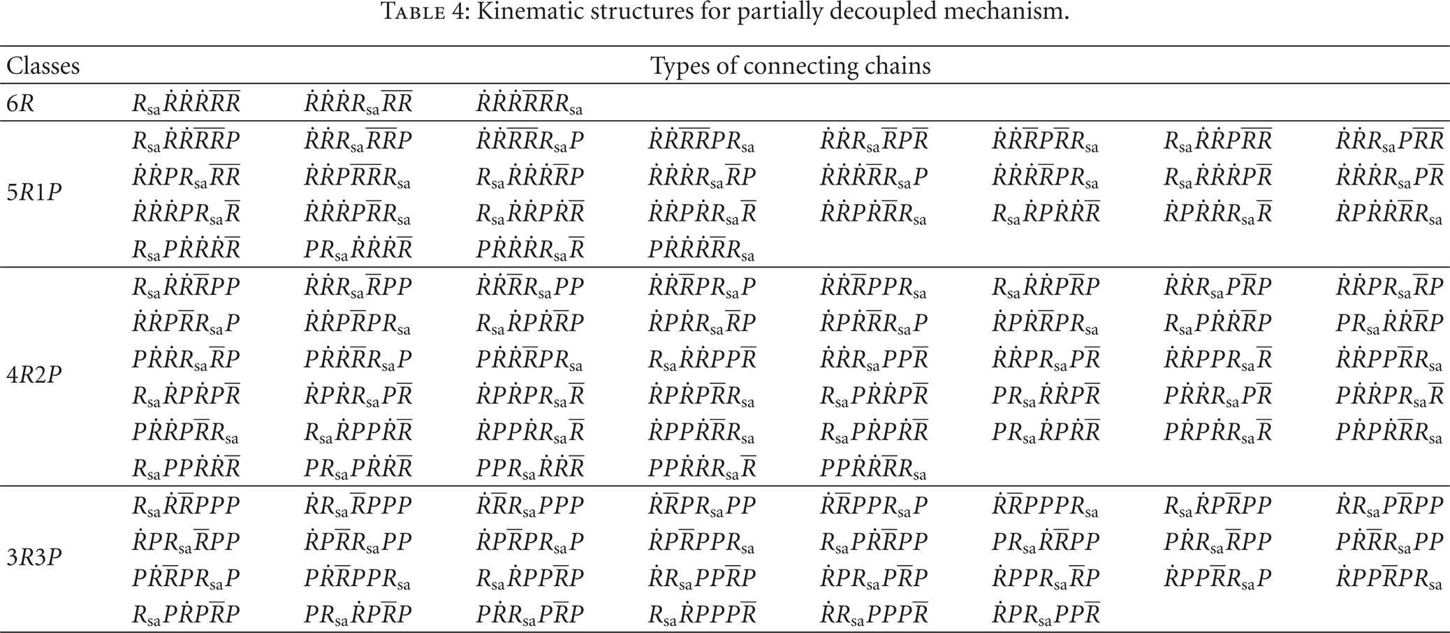
The results are summarized in Table 4. In all mechanisms listed in this table, the additional revolute joint must be the subactive joint of each connecting chain. An
Kinematic structures for partially decoupled mechanism.

6. Kinematic Design of Prototype Manipulator
This section discusses the kinematic design of a TPMFAO taking the partially decoupled parallel mechanism with
6.1. Mechanism Configuration
The mechanism configuration and the definition of kinematic constants are given in Figure 8. The target application is a manipulator for assembly. Large utility workspace, fine orientation-adjustment capability, and small translational motion coupled with rotational motion when actuating subactive joints are required in such an application.

Kinematic constants of the 3-
6.2. Utility Workspace
The reachable workspace of a manipulator is divided into areas according to singularity. Then, the area in which the manipulator can actually work is limited to one of the divided areas that do not contain singularity. Such areas are called “subworkspaces.” Once the manipulator is assembled, it can move inside a subworkspace. The largest subworkspace is called the “utility workspace” [7]. At a singular point of a parallel manipulator, the absolute value of the Jacobian matrix becomes zero or infinity, and the sign of the determinant of Jacobian matrix changes around the singular point. Based on this, the boundaries of subworkspaces can be identified, and the utility workspace can be obtained. The volume of the workspace is evaluated by the normalized volume index NVI [22]. We calculated NVI by

Here, the characteristic length L is
6.3. Orientation-Adjustment Capability
The resolution of the platform orientation in the fine adjustment by the subactive joints is important as an evaluation item of orientation-adjustment capability of a TPMFAO. It is determined by the submatrix, BPD, of the matrix, JPD, in (2). Taking the worst case into consideration, the maximum singular value of BPD is proposed as the index of the orientation-adjustment capability. This is denoted by OAC.
6.4. Coupling Index
Small translational motion coupled with rotational motion by the subactive joints is required to improve the pose accuracy of TPMFAO. The magnitude of this translational motion can be represented by the matrix,
6.5. Kinematic Design and Performance Evaluation
We considered the volume of the utility workspace of the 3-
Kinematic constants of the prototype manipulator.

The evaluation indices in the reachable workspace of the manipulator are shown in Figure 9. We can see from Figure 9(a) that the manipulator can have good kinematic and static characteristics in the upper region of the reachable workspace (
Distributions of evaluation indices in the reachable workspace.

6.6. Prototype Manipulator
We built a prototype manipulator based on the results of kinematic design. Its overview is shown in Figure 10. We also constructed its control system. Figures 11 and 12 show the inclination angle of the platform (orientation error of the platform) and the evaluation index CI in the cases where trajectories of the platform are given so that the platform moves along the line (X-axis) without changing its orientation. In these experiments, no adjustment or compensation by the subactive joints was given while only the main active joints were actuated. Displacement X and orientation error

Overview of the prototype manipulator.

Result of trajectory tracking at (ω x , ω y , ω z )=(0,0,0) (X: from 0 to 0.11 m, Y = 0, Z = 0.35 m).

Result of trajectory tracking at (ω x , ω y , ω z )=(0,0,0) (X: from 0 to −0.12 m, Y = 0, Z = 0.35 m).
7. Conclusions
We presented a kinematic design of a translational parallel manipulator with fine adjustment capability of platform orientation (TPMFAO). First, to clarify all possible kinematic structures whose main motion is translation and submotion is rotation, we carried out structural synthesis of fully and partially decoupled mechanisms based on the synthesis results of 3-dof translational and rotational parallel mechanisms. Based on these, we designed and built a prototype TPMFAO. Through theoretical and experimental investigations, we confirmed the effectiveness of our approach and clarified our future work target.