
Abstract
This paper is an attempt to design a decoupled A/B-axis tool head with parallel kinematics, due to the increasing demand for A/B-axis tool heads in industry, particularly in thin wall machining applications for structural aluminium aerospace components. In order to carry out further analysis, the method of orientation description based on the azimuth and tilt angles is introduced, which is a convenient method describing kinematics, parasitic motions, and orientation workspace. For the purpose of optimal design, three indices are defined to evaluate the force transmission performance of the tool head. They have obvious physical significance and are dependent of any coordinate system. Based on the indices and their performance atlases, the optimization process is presented in detail. The parasitic motions and orientation capability of the designed tool head are analyzed finally. The results show that the designed device is far from singularity, has good force transmissibility, and has very high tilting angle. The indices and analysis and design method used here should be said to be extended to other parallel robots.
1. Introduction
Generally, a tool head that can rotate about the x-axis and y-axis is defined as A/B-axis tool head, and that can rotate about the x-axis and z-axis is defined as A/C-axis tool head. Most of the multifunction milling machines have a tool head with two rotational degrees of freedom (DOFs), and the tool head usually adopts the serial architecture, such as the A/C-axis tool head proposed in [1]. In order to reduce the machining time and deformation of the work piece, A/B-axis tool heads are used instead of the A/C-axis tool head in the manufacture of structural aircraft parts with thin walls. Such kind of serial tool head usually has complicated transmission system, huge structure and high weight, it is difficult to install, and moreover, the manufacture cost and maintenance fee is relatively high. And, in practical engineering application, this serial architecture has many disadvantages such as inconvenience for locus planning and control difficulty since its two rotations are not coupled motions due to its serial kinematic structure. Although the A/B-axis tool head with parallel kinematics has relatively small rotational angle compared with the serial tool head, it has high manufacturing efficiency and much smaller deformation made to work piece. What is more, the parallel manipulator has the advantages of high stiffness, high velocity, compactness, time-saving of machining, high load/weight ratio, and low moving inertia. So, the A/B-axis tool head with parallel kinematics has the absolute advantage in the manufacture of structural aircraft parts with thin walls which needs mass cutting and high speed. Recently, parallel A/B-axis tool heads with high tilting angle have become the most important and fundamental part in the manufacturing field of key structural aircraft parts. DS Technology in Germany has developed a machining tool head [2], the Sprint Z3, and FATRONIK in Spain has developed the Space 5H tool head [3]. Both of them have made great success in engineering application. The Z3 tool head is based on a 3-DOF spatial 3-PRS (P, R, and S stand for prismatic, revolute, and spherical joints, resp.) parallel manipulator. It has a translational DOF along the z-axis and two rotational DOFs about the A and B axes, respectively. In this kind of tool head, the most important is the two rotational DOFs that provide the coupled tilting motion. And, generally, some machining centers just need the two rotational DOFs. So, the development of an A/B-axis tool head with parallel kinematics is becoming more and more popular.
For parallel manipulator, optimal design is one of the most important and challenging problems and is attracting more and more efforts [4–7]. There are two issues involved: performance evaluation and dimension synthesis. Having designed a mechanism, it is necessary to evaluate its performance. So, the first problem is of most importance and should be reconsidered due to the doubt of the mostly used index, that is, local conditioning index (LCI) [8]. The second problem is to determine the dimensions (link lengths) of the mechanism, which is suitable for the task at hand. It is one of the most difficult issues in the field.
Several well-defined performance indices which are popular in the field of serial mechanism, such as manipulability, workspace, singularity, dexterity, stiffness, and accuracy, have developed extensively and applied to the design of parallel manipulator. The LCI, which is the reciprocal of the condition number of Jacobian matrix, is usually used to evaluate the accuracy, dexterity, and distance to singularity of a parallel manipulator. For this reason, the LCI has drawn much more attention. However, a recent study [8] reviewed the LCI and global conditioning index (GCI) that is the computation over a kind of workspace of the manipulator. The study found serious inconsistencies when these indices are applied to parallel manipulators with combined translational and rotational degrees of freedom and conclude that these indices should not be used in parallel manipulators with mixed types of DOFs (translational and rotational). To eliminate the singularity and its near configurations, most researchers use the local conditioning index (LCI). Usually, a good-condition workspace [9] or effective workspace [10] was defined with respect to a specified minimum LCI. However, the minimum is still arbitrary or comparative since we cannot give it a defined value due to its frame-depended characteristic. Generally, it is impossible to define a mathematical distance to a singularity for a parallel manipulator. Thus, the authors think that the LCI cannot be used in parallel manipulator, but not only those with mixed type of DOFs.
As is well known, the planar four-bar mechanisms have been studied for a very long time, longer than that of serial robots and much longer than that of parallel manipulators. The transmission angle is an important index for the design of such a mechanism as was pointed out by Alt [11], who defined the concept, using the forces tending to move the driven link and tending to apply pressure to the driven link bearings as a simple index, to judge the force-transmission characteristics of a mechanism. So, the transmission angle is an index evaluating the quality of motion/force transmission. By means of the index of transmission angle, the quality of motion/force transmission in a mechanism can be judged in the design stage. And it helps to decide the best from a family of possible mechanisms for the most effective force transmission [12]. Also, the transmission angle of a mechanism provides a very good indication of the quality of its motion, the accuracy of its performance, its expected noise output, and its cost in general [13]. Although a good transmission angle is not a cure-all for all design problems, as is pointed out in [14], for many mechanical applications it can guarantee the performance of a linkage at higher speed without unfavorable vibrations. The study [15] shows that when the transmission angle equals to 90°, the most effective force transmission takes place and the output motion becomes less sensitive to the manufacturing tolerances on the link lengths, clearance between joints, and change of dimensions due to thermal expansion. A large transmission angle usually leads to reasonable mechanical advantages and a high quality of motion transmission. The study of link mechanisms shows that transmission angle is significant not only as an indicator of good force and motion transmission but also as a prime factor in the linkage sensitivity to small design parameter errors. The smaller the transmission angle is, the more sensitive the linkage will be [16]. Mechanisms having a transmission angle too far from 90° exhibit poor operational characteristics such as noise and jerk at high speeds [17, 18], and many studies have reached the conclusion that if the transmission angle becomes too small, the mechanical advantage becomes small, even a very small amount of friction will lead the mechanism to jam, and if it is 0, self-locking takes place. For the purpose of high speed, high accuracy, and high quality of motion transmission, the most widely accepted design limits for the transmission angle are (45°,135°) [18] or (40°,140°) [11].
A planar four-bar mechanism is a single-closed-loop system. A parallel manipulator is a multiclosed-loop system. Usually, a fully parallel manipulator has more or less the characteristic of a planar four-bar mechanism. We suggest that the design concept of the four-bar mechanisms could be used in the design of a parallel manipulator. In this paper, the local and global transmission indices (defined in Section 5.2) based on the concept of transmission angle will be proposed as indices in the optimal design of an A/B-axis tool head with parallel kinematics, which can be kinematically considered as the combination of two slider-crank mechanisms at any moment.
Many methods have been proposed for the dimensional optimization of a specified mechanism. The most common method is the objective-function-based optimal design. According to this method, an objective function with specified constraints must be established, and then a search is conducted to find the result utilizing an optimum algorithm. Not only is this method time consuming, but it is difficult to reach the globally optimum target because of the infiniteness of the individual parameters, the antagonism of multiple criteria, and the assignment of initial values. The most serious drawback is that it provides only one solution for a design problem. This is actually unreasonable for a practical design, since it is impossible to predict any application in advance and to know whether a particular design is the only solution.
The ideal dimensional optimization method would be that using the performance charts (atlas), which is widely used in classical design. A performance atlas can show, visually and globally, the relationship between a performance index and the associated design parameters in a limited space [19]. Moreover, it can show how antagonistic the involved indices actually are. Compared with the result achieved by the objective-function-based method, the result of this optimal method is comparative and fuzzy. However, it is more flexible, because it provides not only a single solution, but also all possible solutions to a design problem. This means that the designer can adjust the optimum result appropriately according to the particular design conditions he is dealing with [20]. This method will be extended to the dimensional optimization of the A/B-axis tool head with parallel kinematics.
The remainder of this paper is organized as follows. The next section describes the structure of the proposed tool head with different configurations. Section 3 introduces the method of orientation description of the tool head and analyzes the relationship between orientational angles and output angles of the two legs, and then, the parasitic motions are given. Section 4 investigates the inverse kinematics of the tool head. Section 5 recalls the classical concept of transmission angle, defines the forward and inverse transmission angle, proposes some indices, and then, plots performance atlases for these new indices and presents the optimal design using the atlases. Section 6 analyzes the orientation capability and parasitic motions of the tool head given in Section 5. Development of the tool head is presented in Section 7 and conclusions are given in Section 8.
2. Structure Description
The A/B-axis tool head with parallel kinematic, shown in Figure 1, contains a moving platform which connects to the base through two legs. The first leg contains a fixed length link and a bracket, the bracket can rotate about the y-axis through a revolute joint, another revolute joint connects the link to the bracket, the other end of the link is connected to an active slider through a revolute joint, and the slider is attached to the base by a prismatic joint whose move direction is vertical (Figures 1(a), 1(c), and 1(d)) or horizontal (Figure 1(b)). The second leg contains a fixed length link (Figures 1(a), 1(b), and 1(c)) or an extensible link which is active (Figure 1(d)). For the models shown in Figures 1(a), 1(b), and 1(c), the link is connected to the active slider through a universal joint. For the model shown in Figure 1(d), the active link is connected to the base through a screw joint and a universal joint. The moving platform is connected with the two legs by two revolute joints, respectively. In order to make it move, the axes of the revolute joint fixed to the bracket and that of the universal joint in y-axis direction must be collinear. The rotational axes of the moving platform are orthogonal but not coplanar for the models shown in Figures 1(a) and 1(b); they are orthogonal and coplanar for the models shown in Figures 1(c) and 1(d). It is not difficult to find that the two rotations of any one of the structures are decoupled.
The CAD models of the A/B-axis tool head with parallel kinematics (P-prismatic joint, R-revolute joint, U-universal joint, H-helical joint, and the underlined joints are active.).

From the above description, one can see that, at any moment, this kind of A/B-axis tool head can be considered as the combination of two slider-crank mechanisms. The slider-crank mechanism, shown in Figure 2, is a classical planar four-bar mechanism. And such a combination can make sure that this A/B-axis tool head is decoupled. As is well known, a decoupled mechanism is easier to control and achieve higher accuracy.
A slider-crank mechanism.
We may see that the models shown in Figures 1(a), 1(b), and 1(c) are similar in kinematics but are different from that shown in Figure 1(d). In this paper, we will mainly focus on the models shown in Figures 1(a) and 1(d). For the former model, its kinematic scheme is shown in Figure 3, where the two rotational axes of the moving platform are orthogonal but not coplanar. Thus, such a mechanism has parasitic motion which will be analyzed in the next section. We call such a case the case

kinematical scheme of the model with parasitic motions (Figure 1(a)).

kinematical scheme of the model with no parasitic motion (Figure 1(d)).
3. Orientation Description of the Parallel A/B-Axis Tool Head
Most researchers have used Euler angles to describe the orientation of a parallel manipulator. For the manipulator discussed in this paper, this method is inconvenient to describe the orientation and to analyze the kinematic problems. We will use another method introduced in [21], which is suitable for the task at hand. For any feasible orientation of the moving platform of a mechanism with two rotational DOFs, its two rotations can be obtained from the reference (home) orientation by a single rotation about a line passing through the center of the moving platform. Here, two angular parameters are involved. The azimuth angle, denoted by ϕ, defines an a-axis passing through the platform center o′ (Figure 3) or o (Figure 4) and lying in the o′-

where 프 denotes
As analyzed above, this mechanism can be considered as the combination of two slider-crank mechanisms. Then, there are two independent rotational angles about the y-axis and x-axis or x′-axis, respectively, and they are referred to as α and β, correspondingly.
In order to carry on further analysis, we need to find out the relationship between

The projective relationship between (ϕ,θ) and (α,β).
Point P denotes the tip of the tool, and o′ is the center of the moving platform. Angular parameter α is defined as the rotational angle from home orientation of
Letting

That is

For the case
Please note that, for the second leg shown in Figure 7(a),

The first leg of the tool head.
The second leg of the tool head: (a) for the model in Figure 1(a) and 1(b) for the model in Figure 1(d).

Then, the parasitic motions can be described as

For the case
4. Inverse Kinematic Analysis of the Tool Head
4.1. Inverse Kinematics of the Tool Head with Parasitic Motions
For the case
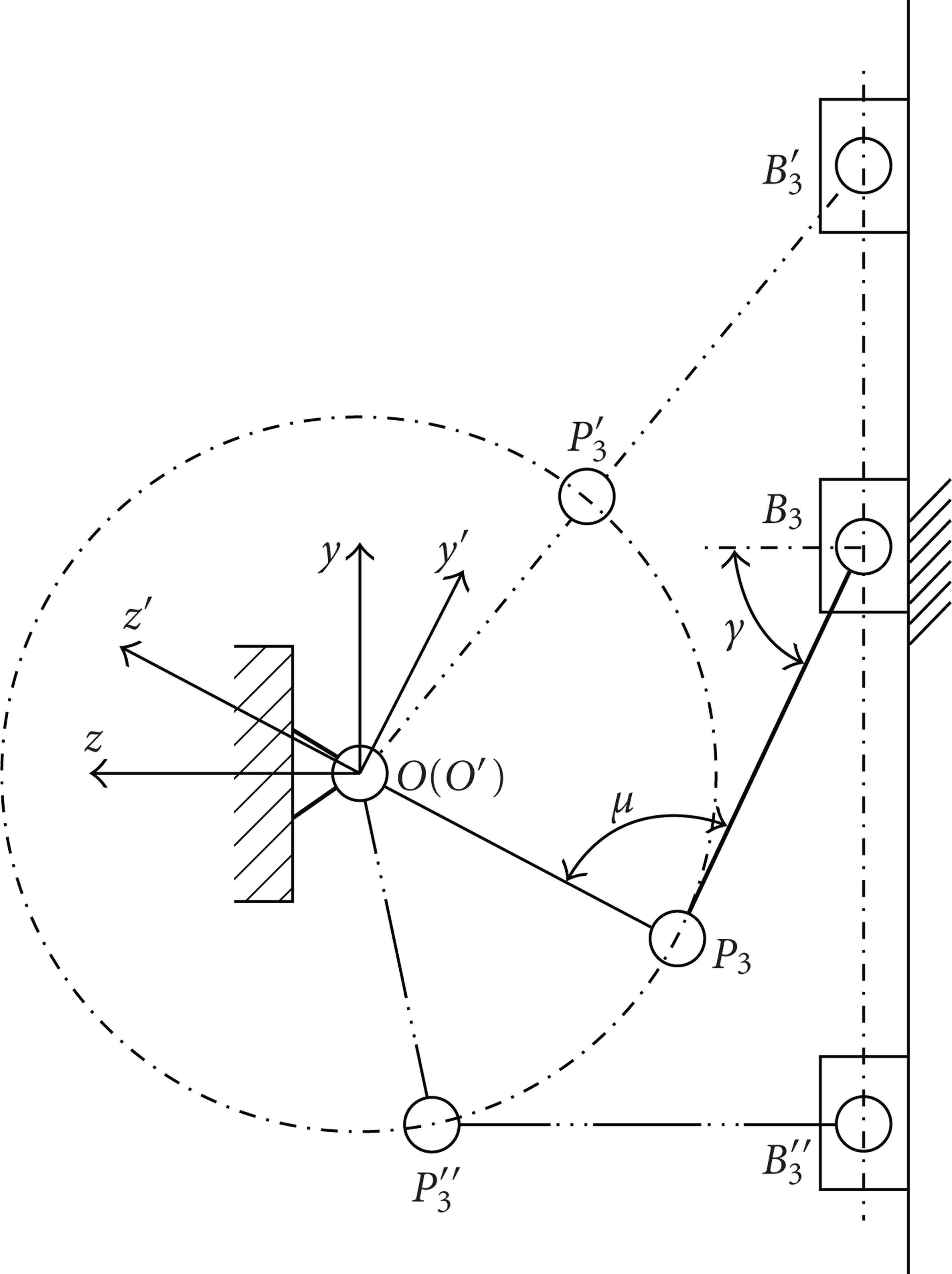
A mobile reference frame o′-
As shown in Figures 6 and 7(a), the planar schemes of the first and second legs are similar in configuration. The geometric parameters will be
Vectors

The kinematic problem of the tool head can be solved by writing the constraint equations:

Then, there are
The inputs y and z can be obtained as


where

For a given pose
4.2. Inverse Kinematics of the Tool Head without Parasitic Motions
For the case
The fixed global reference frame o-
Compared with case
The point c1 locates at the intersecting line of the o-yz plane and the horizontal plane passing through the point o. The geometric parameters will be
Therefore, for case
5. Kinematic Optimum Design
5.1. Transmission Angle
The transmission angle is something we are very familiar with without realizing it; it is a classical concept in the field of four-bar mechanism design. In fact, in our daily life, we frequently try to move something which is constrained in some way and cannot be moved freely, such as the handle of a crank, a curtain on a rail, and a sliding door. In all of these cases, the object may not be able to be moved even when we exert pressure against it. Let us take the case of the handle of a crank as an example. As shown in Figure 8, the crank is attached to the base with a constant counterclockwise moment M; to move it, we must apply a right-hand force F at the end of the crank; when the direction of the force is constant, depending on the position of the end point it may be more or less easy to start rotating. This is actually a matter of the transmission angle. Since the direction of motion of a crank is always perpendicular to the crank, the smaller angle between the force and crank is defined as the transmission angle, denoted as μ. When the force is normal to the crank, that is, identical to the direction of motion, force transmission is most effective; when the force is perpendicular to the direction of motion, force transmission is very inefficient.

The handle of a crank.
For the planar four-bar mechanism shown in Figure 9,

Transmission angle.
When the transmission angle deviates significantly from
Meanwhile, at the moment that the angle γ between the input link
Take the slider-crank mechanism shown in Figure 2 as an example, where angle
5.2. Definition of Some Indices
5.2.1. Local Transmission Index (LTI)
The condition number of the Jacobian matrix is an index that has been used successfully in the design of serial robots. Although the condition number is depended on the coordinate frame, it has the main advantage of describing the kinematic behavior of a robot by means of a number. The index has also been applied in the analysis and design of parallel robots. It was used as an index to evaluate the accuracy/dexterity [23, 24], to describe the closeness of a pose to a singularity of a parallel robot [25, 26]. In an optimal design, the condition number (or its reciprocal) was used to define a useful, good-condition, or effective workspace with a specified minimum LCI [10, 19, 27]. However, the minimum is still arbitrary or comparative since we cannot give it a definite value. Generally, it is not possible to define a mathematical distance to a singularity for a parallel robot [8]. Instead of LCI, another index will be defined here.
Following the definition of transmission index proposed in [28], an index based on the transmission angle is defined as

where

A larger χ indicates better motion/force transmission. Since at a different pose the transmission angles will be different, the index χ is referred to as the local transmission index (LTI) in this paper. The angle is defined as the figure formed by two lines diverging from a common point, or as that formed by two planes diverging from a common line. Thus, the angle is usually measured by the ratio of two linear parameters. Therefore, the LTI is definitely independent of any coordinate frame. This is one of its advantages and is the most important for the optimal design of mechanisms.
For the purpose of high speed and high quality of motion/force transmission, the most widely accepted range for the transmission angle is
Then, unlike the LCI, the LTI has a significative limitation to its application.
It is worth mentioning that, in [26, 29], the authors defined a transmission index, that is, cosα, by using the concept of the pressure angle α. Since the pressure angle is the complement of the transmission angle, the two definitions have the same significance. However, the authors did not define indices to evaluate a workspace with good transmission and to judge the effectiveness of motion/force transmission of a robot over a whole workspace. The two kinds of indices will be very important in the design of a parallel robot.
5.2.2. Good-Transmission Workspace (GTW)
With the minimum of LTI, that is,
5.2.3. Global Transmission Index (GTI)
The LTI χ can only judge the effectiveness of motion/force transmission of a robot at a single pose. Usually, a robot performs a task in a specified workspace but not at a pose. In a practical design, we should make a decision whether a robot is good or not by taking into account the behavior within a considering workspace. In order to measure the global behavior of the motion/force transmission over the whole GTW, following the definition of GCI suggested in [30], a global transmission index (GTI) is defined as
in which W denotes the good-transmission workspace, n the number of transmission angles, and
Undoubtedly, for manipulators with different link lengths, their GTWs will be the same. If such a case occurs, we cannot judge which robot is better with respect to the GTW index itself. However, with the same GTWs, their GTIs may be different. The two indices, GTW and GTI, together will help us to design a robot optimally. Additionally, for a specified design problem, other performance indices such as stiffness and accuracy may be involved in identifying a better solution. This is not the content of the paper. To demonstrate the use of the proposed indices, that is, LTI, GTI, and GTW, the subsequent section will discuss the optimal design of the A/B-axis tool head with parallel kinematics proposed in Section 2.
5.3. Performance Atlas
As analyzed in Section 2, to optimize the proposed A/B-axis tool head, we should first analyze the slider-crank mechanism.
For the case

where

Parameter design space of the slide-crank mechanism.
We can easily get the relationship between

We should first find out the usable workspace, which is defined as the maximum continuous workspace that contains no singular loci inside but bounded by singular loci outside, in the parameter design space. For the slider-crank mechanism, the usable workspace can be written as
The usable workspace of the slider-crank mechanism.
As shown in Figure 6, according to (16), the forward and inverse transmission angles of the normalized mechanism can be obtained as

where ω is the output angle, and
Suppose that when

Figure 12 gives the relationship between
Atlas of the good transmission workspace (GTI) of the slider-crank mechanism.
The relationship between good transmission index (GTI) and
Atlas of the good transmission index (GTI) of the slider-crank mechanism.
For the case
Through similar process of normalization, we can get the normalization parameters l1 and l2 for L1 and L2. The parameter design space of the extensible link mechanism is constrained by

where
For the extensible link mechanism, only one transmission angle, that is,
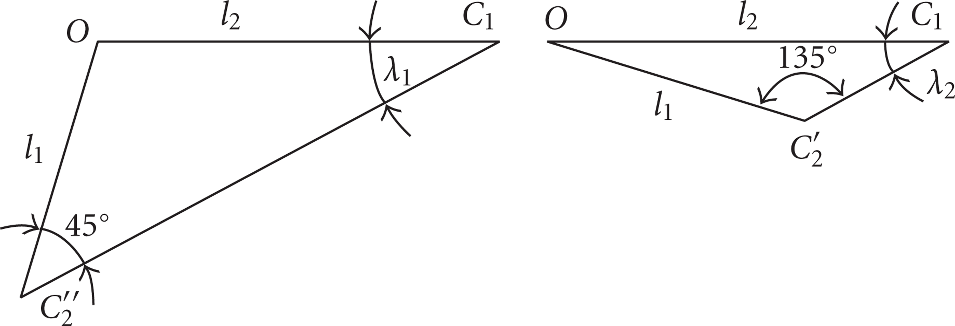
The relationship between λ1 and λ2 when
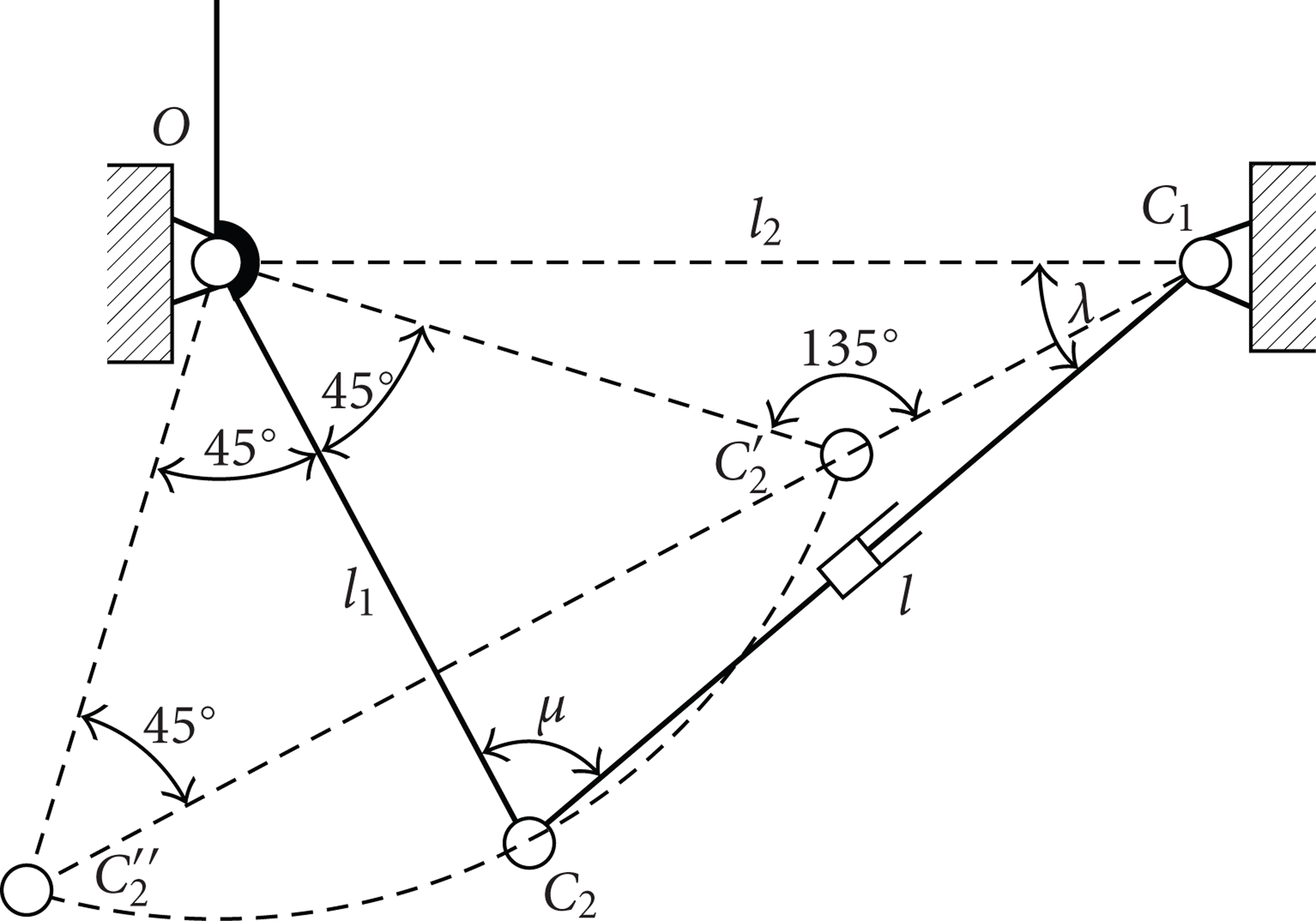
The rotational capability of the extensible link mechanism when
From Figure 14, we can get

Then

That is to say that points C1,
So, the angle between
Figure 16 shows the relationship between GTW and l1 (
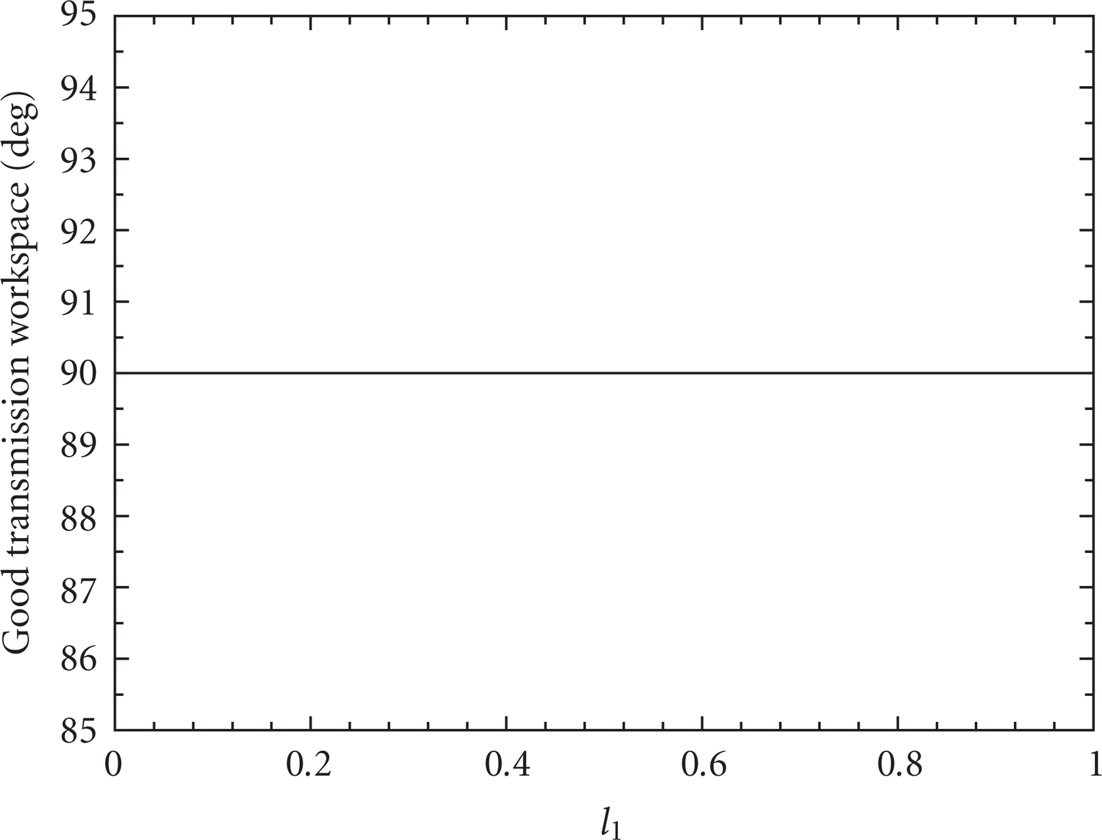
The relationship between the good transmission workspace (GTW) and l1.
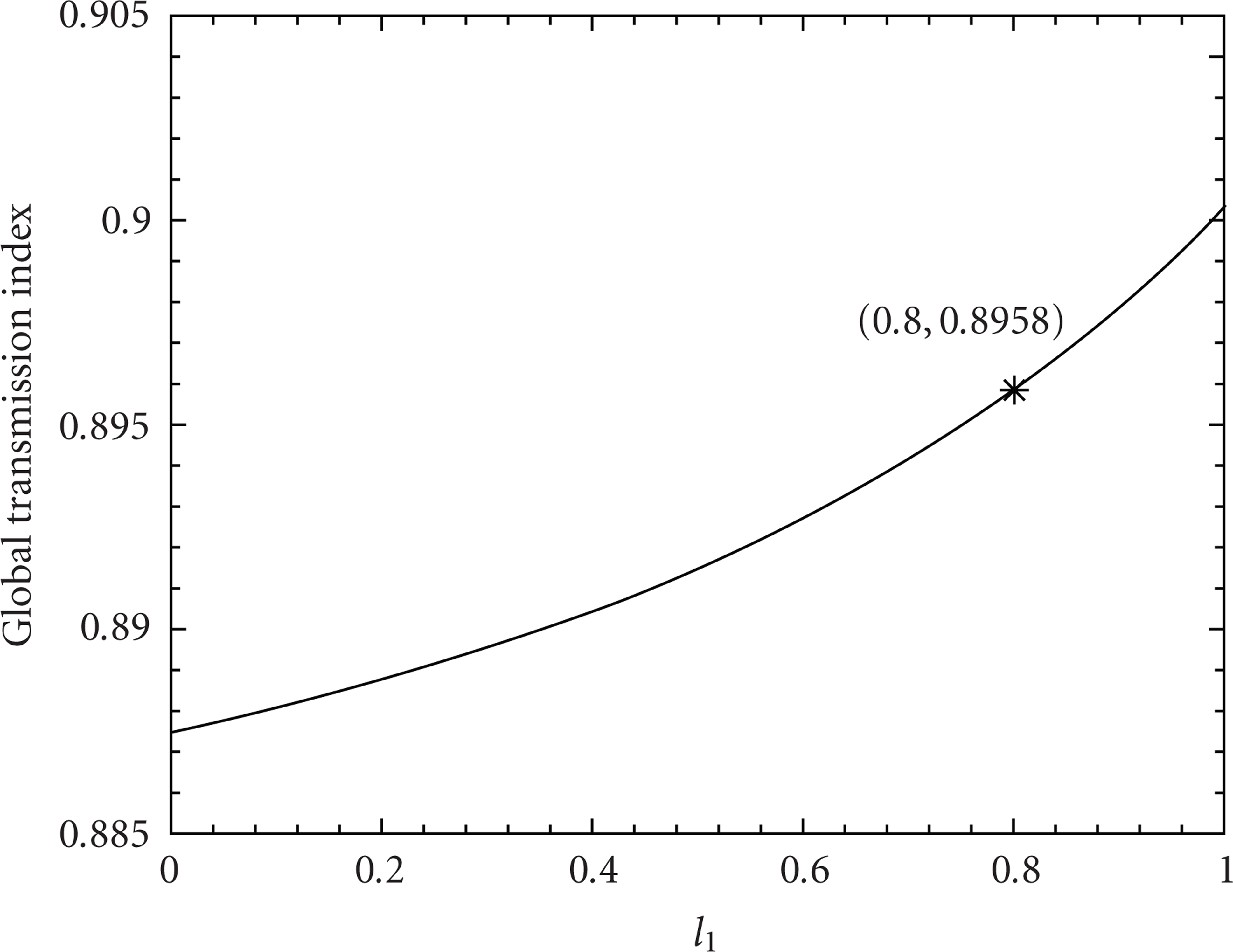
The relationship between the good transmission index (GTI) and l1.
5.4. Dimension Optimization Using the Performance Atlases
For the case
Step 1.
Identification of an optimum region in the parameter design space.
Please note that since all design conditions cannot be the same, the identification of an optimum region is up to the designer. Here, we just give an example.
For the slider-crank mechanism, an optimum region Ω will be determined with respect to the constraints of
The identified optimum region contains all possible nondimensional solutions for the design problem. Since a nondimensional robot in the parameter design space and all of its corresponding dimensional mechanisms are similar in performance [20], the final design result based on the mechanism in the optimum region will be optimal. Therefore, the next step is to find an acceptable solution candidate in the optimum region.
An optimum region for the slider-crank mechanism when
Step 2.
Selection of a solution candidate from the optimum region.
The obtained optimum region Ω contains all possible solutions for the design. Since there is no best but only a comparatively better solution for a design problem, one may pick up any nondimensional robot from the region.
We here pick up the nondimensional robot with parameters
Step 3.
Determination of the dimensional parameters R1, R2, and R3 with respect to the desired workspace.
According to the normalization method introduced in [20, 31], we should first determine the normalization factor, that is, D. This factor can be obtained by comparing the desired workspace of a design problem and the workspace of the nondimensional mechanism selected from the optimum region.
For the slider-crank mechanism, the output angle is only dependent on the ratio of related linear parameters but not on any one of the parameters itself, we cannot determine the normalization factor D with respect to the orientational workspace
Step 4.
Calculation of the input range and adjusting angle.
The input range to reach the desired workspace can be calculated by means of the inverse kinematic equations (9) and (10). In Step 2, we have got
Step 5.
Checking the design result and adjusting, if necessary, the design solution.
In this step, what should be checked depends on the application. For example, the designer may check whether the input range is suitable for his preferred commercial actuator. Whatever is checked, if the solution is not satisfactory, the designer can return to Step 2 and pick up another nondimensional mechanism, or even return to Step 1 to identify another optimum region, adjusting the design solution until the solution is satisfactory. This is actually the advantage of this design method.
Similarly, we still pick up the nondimensional robot with parameters
Then, the adjusting angle is
For the case

The second leg in the case
6. Orientation Capability and Parasitic Motions Analysis
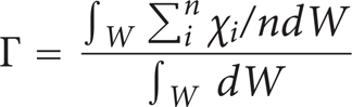
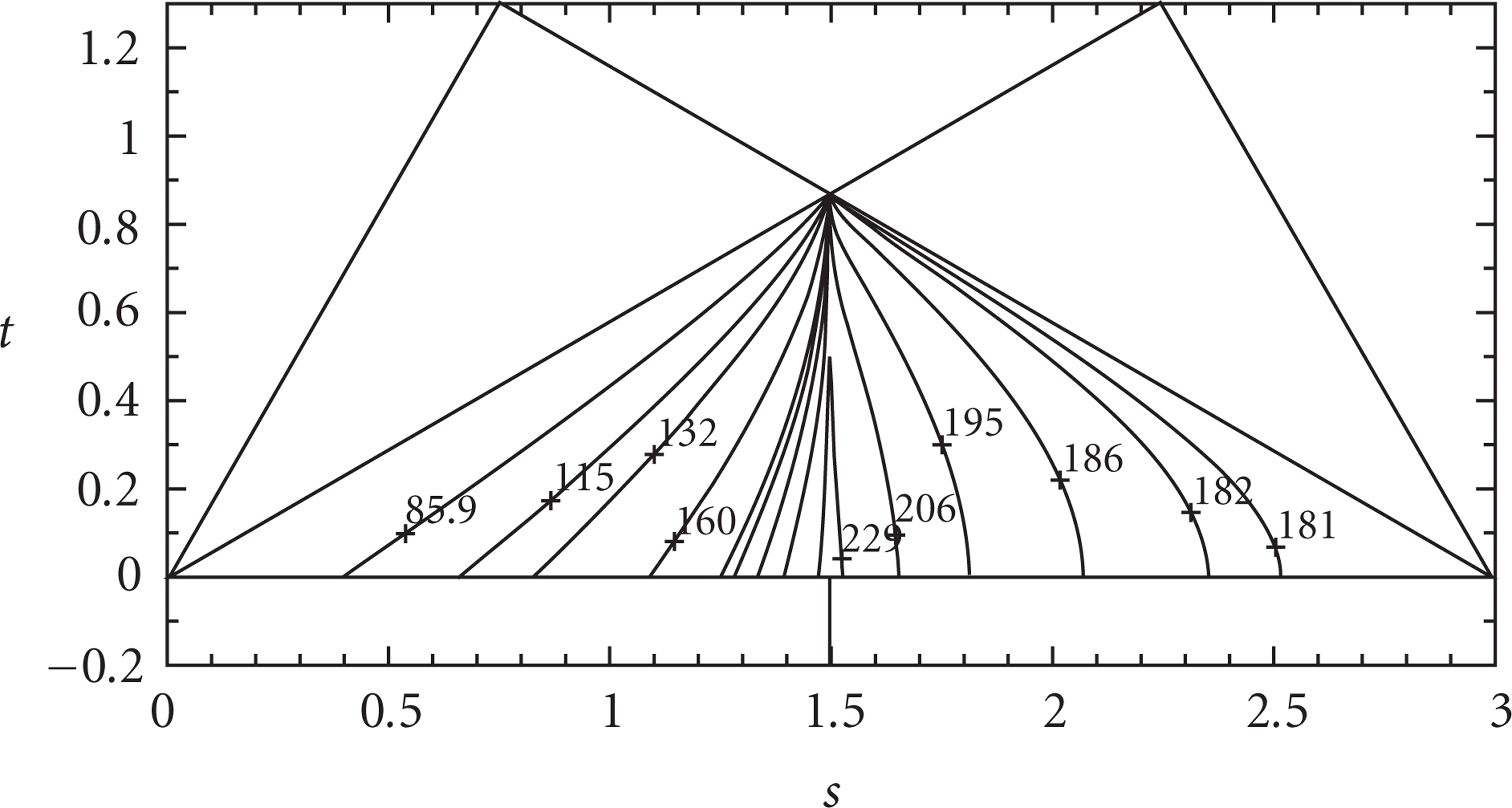
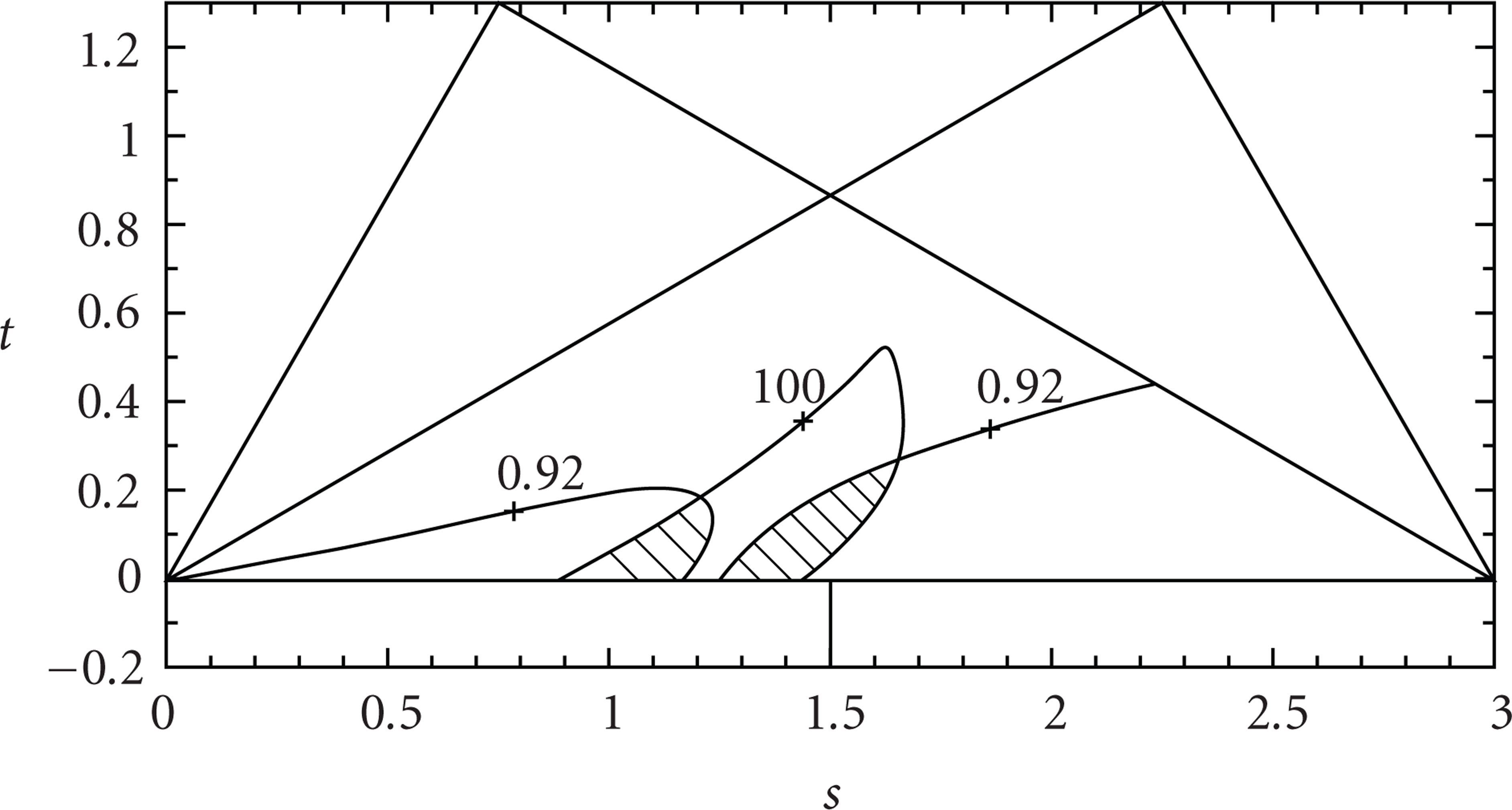
In Section 3, we have introduced the method of orientation description of the tool head. In this section, we will investigate the relationship between theazimuth and tilt angles and thegood transmission workspace of the designed tool head in Section 5.
We can get the output angles (α and β) of the first and second legs from (3).
For the case

The orientation workspace of the tool head in the case
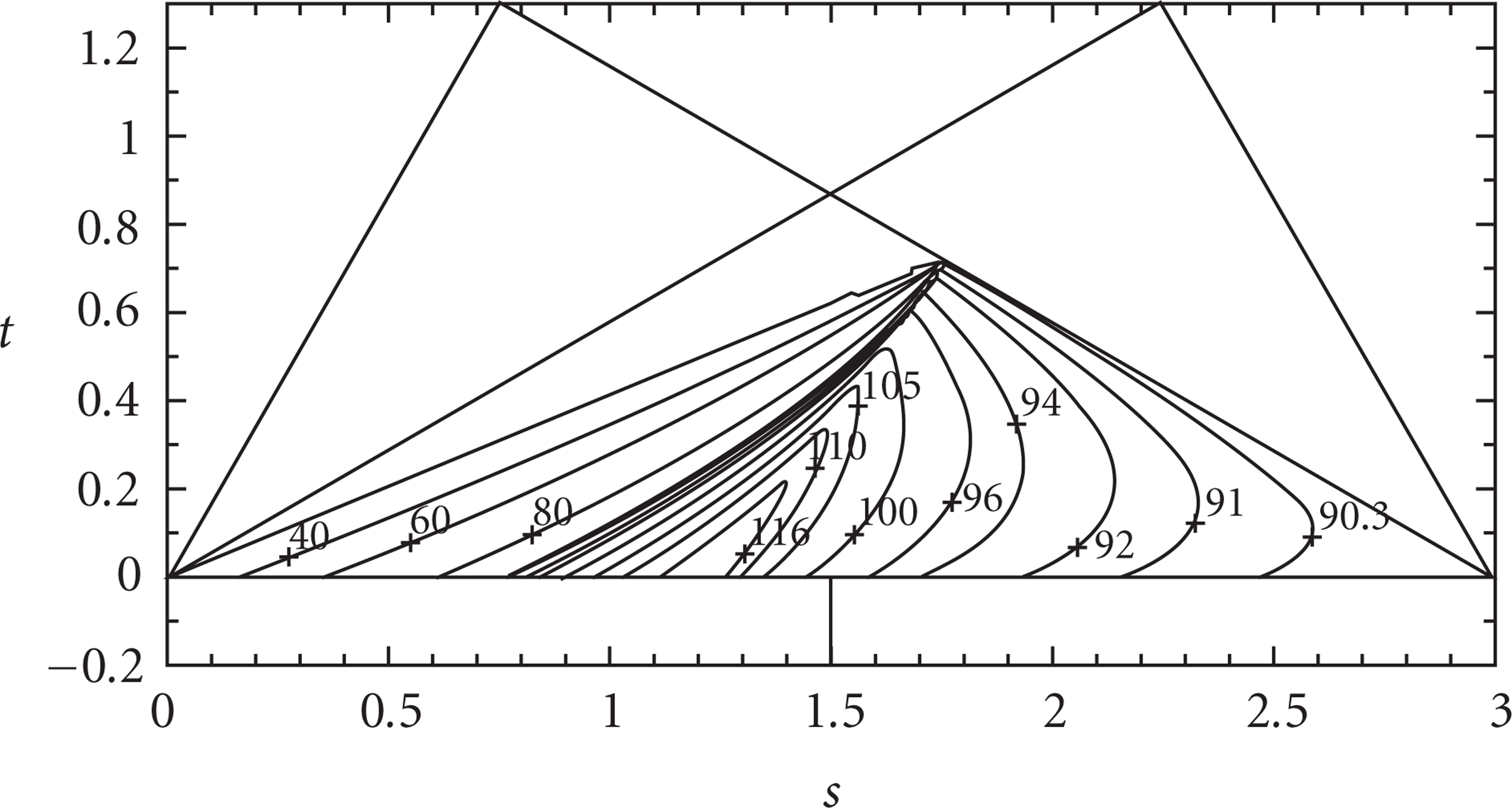
The parasitic motions can be got from (4). In order to know the relationship between the orientation angles and the parasitic motions, we need first to find out the relationship between the orientation angles and the output angle α of the first leg, as shown in Figure 21. Figure 22 shows the relationship between the orientation angles and the output angle α. Then, from Figures 21 and 22, we can clearly know how the parasitic motions are.

The relationship between the orientation angles and the output angle α of the first leg in the case

The relationship between parasitic motions and the output angle α of the first leg in the case
For the case

The orientation workspace of the tool head in the case
7. Development of the Tool Head
We have built the real model of this kind of mechanism, as shown in Figures 24 and 25 and may have them manufactured and carry out some experiments further.
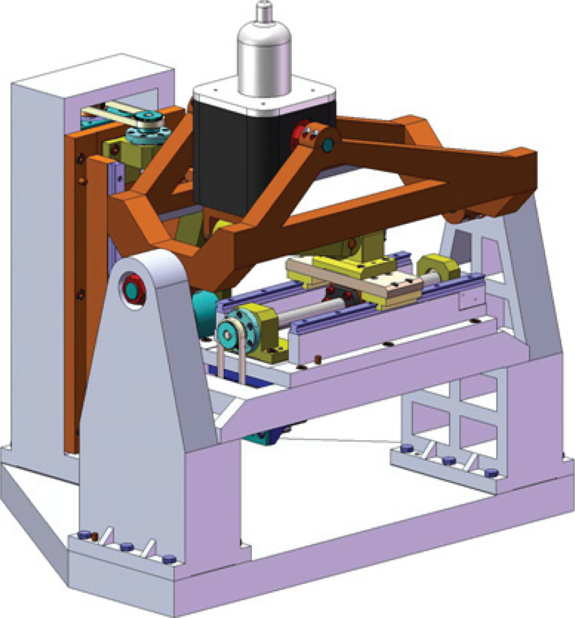
The real model of the mechanism in the case

The real model of the mechanism in the case
8. Conclusion
In this paper, we have introduced and analyzed an A/B-axis tool head with parallel kinematics, which is kinematically decoupled. Firstly, we have introduced a method of orientation description of the tool head, that is, the azimuth and tilt angles. Then, the transmission angle was recalled and the forward and inverse transmission angles were defined accordingly. Based on the concept of transmission angle, we proposed and defined some new indices, that is, local transmission index (LTI), good transmission workspace (GTW), and global transmission index (GTI). Then, the performance atlases and optimal design of the tool head based on these indices are presented. Finally, we analyzed the orientation capability and the parasitic motions of the designed tool head. The results show that the azimuth and tilt angles are convenient to describe the orientation of the tool head discussed here, and the indices proposed in this paper have obvious physical significance and could be extended to the analysis and design of other parallel robots.
Footnotes
Acknowledgments
This work was supported in part by the National Natural Science Foundation of China under Grant 50775118, the National Basic Research Program (973 Program) of China (no. 2007CB714000), and by Program for New Century Excellent Talents in the University of China.