
Abstract
An experimental investigation was conducted, both thermally and visually, on a three-dimensional flat-plate oscillating heat pipe (3D FP-OHP) to characterize its performance under localized heat fluxes while operating in the bottom heating mode and charged with acetone at a filling ratio of 0.73. The cooling area was held constant and three heating areas of 20.16
1. Introduction
Due to the ongoing miniaturization of electrical components and the general advancement of technology, the thermal management of high heat fluxes is becoming a pivotal requirement for product development and application. Although conventional, wicked heat pipes have provided adequate thermal solutions for many applications, their functionality at high heat fluxes is hindered by numerous limitations (i.e., form factor, operational limits, etc.). The oscillating heat pipe (OHP), as introduced by Akachi [1], provides a promising alternate solution for high heat flux thermal management. The OHP, a two-phase heat transfer device, typically has no wicking structure and exists either as a closed-loop, serpentine-arranged tube (T-OHP) or an engraved, serpentine-arranged channel on a flat-plate of metal that is sealed—also referred to as the flat-plate oscillating heat pipe (FP-OHP). The inner hydraulic diameter of the pipe (or channel) is made sufficiently small to allow a partially filled working fluid to disperse itself into liquid slugs and vapor plugs via capillary action during operation. The OHP operates when both ends of the tubing/plate thermally interact with a heat source and a heat sink. The heat exchange occurring at both ends continually disturbs the phase of the internal saturated working fluid, resulting in vapor condensation or liquid evaporation. The continual phase change results in a pressure imbalance along the channels of the OHP, which allows for the quasichaotic displacements of the internal working fluid slugs/plugs.
A typical OHP allows for the working fluid to flow within a single plane. However, this traditional design limits the OHP channel density (channels/unit volume) and hence the thermal resistance of the heat pipe at higher heat fluxes. The effects of varying heating conditions, such as heating area, on an OHP have been previously investigated. Xu et al. [2] considered the effects of heating area while experimentally investigating the thermal performance of two aluminum FP-OHPs. Both FP-OHPs had a width of 5 cm and both were charged with either butane or HFC134a. Heating areas were varied by using square copper heat spreaders that had areas of 9 cm2, 16 cm2, and 25 cm2. The heat pipes were dual cooled by submerging the condensing section in a water bath which created a baseline cooling length of 150 mm. It was found that when the evaporator area of the heat pipe was reduced from 25 cm2 to 9 cm2 (64% reduction), the thermal resistance of the heat pipe increased over 340% while at a heat input of 80 W. However, it was found that the reduction in thermal resistance was minimal when the heating area was reduced from 50 × 50 mm to 40 × 40 mm. The maximum heat flux achieved during this investigation was on-the-order of 10 W/cm2. Charoensawan and Terdtoon [3] investigated the effects of two heating lengths (150 mm and 50 mm) on horizontal, closed-loop oscillating heat pipes (HCLOHPs) charged with either distilled water or ethanol with a constant condenser length. The heat pipes were tubular, made from copper, and the internal diameter and the number of turns were varied. It was found that the thermal performance of one HCLOHP was enhanced by decreasing the heating length and increasing the average evaporator temperature. Furthermore, it was found that the optimal filling ratio increased as the heating length decreased. Meena et al. [4] explored the effects of varying the evaporator length on the operational limit of an OHP with check valves (CLOHP/CV) with various working fluids at a filling ratio of 50%. The CLOHP/CV was made from copper, had an internal diameter of 1.77 mm, and had a total of 10 turns. The evaporator lengths consisted of 15 cm, 10 cm, and 5 cm on where the condenser length was varied to have the same length as the evaporator. It was found that when the evaporator length increased, the critical heat flux decreased for all investigated working fluids. Wang and Shigefumi [5] investigated the effect of varying the heating and cooling lengths on the optimal performance of an OHP. It was suggested that the heating and cooling lengths should be equal at lower filling ratios, and that utilizing a heating length greater than the cooling length is optimal for higher filling ratios. Zhang and Faghri [6] analytically predicted that the reduction of heating section length on an open-loop, tubular OHP reduces the thermal performance of the heat pipe as a result of decreased fluid movement. Borgmeyer and Ma [7] measured the internal fluid oscillation frequencies and velocities for an operating FP-OHP sealed with an acrylic cover. It was found that the oscillation frequencies and amplitudes generally increased with higher heat fluxes. Yang et al. investigated the applicability of aluminum FP-OHPs filled with ethanol as heat spreaders [8]. They found that the FP-OHPs operated in multiple heating orientations and that the FP-OHP which utilized 2 × 2 mm2 channels as opposed to 1 × 1 mm2 performed better. It was also found that the average amplitude of thermal oscillations in the evaporator decreased with higher heat inputs.
Although the effect of heating length has been investigated for various OHPs under different experimental parameters, the heat flux levels were relatively low—less than 10 W/cm2. Furthermore, no research has been performed to investigate the effect of highly-localized heating, on where not only the evaporator length but also the overall geometry vary. Hence, the current study will explore the functionality of the 3D FP-OHP under high heat fluxes that are applied in a localized manner. The thermal performance will be characterized using parameters such as thermal resistance, the average evaporator temperature, and the amplitude of thermal oscillations. Using the novel capabilities of neutron radiography, the internal fluid dynamics and void fraction distribution were visualized, and these results will also be presented.
2. Prototype Development
The 3D FP-OHP was designed to manage higher heat fluxes by integrating two layers of channels—allowing more channels to exist per unit volume. In general, the FP-OHP design medium is more advantageous for high heat flux management due to its less-awkward form factor and its ability to spread heat across more OHP channels. The primary consideration for the 3D FP-OHP design, and for any OHP design, was to ensure that the hydraulic diameter of the looped, interior channel was small enough to induce capillary action for the current working fluid. As found by Akachi [1], this critical diameter for a given working fluid is found using

In order to maximize the channel density and minimize the overall dimensions of the device, the hydraulic diameter of the internal channels and channel-to-channel wall thickness was minimized. The current design incorporates a closed-loop, square channel with a hydraulic diameter of 0.762 mm as shown in Figure 1. For the chosen manufacturing process, a “dead perimeter” was implemented which surrounded the internal OHP “channel array” and had a width of 12.70 mm.
The 3D FP-OHP: (a) overall dimensions and (b) photograph.

The 3D FP-OHP utilizes two layers of channels on where the OHP array on each layer has 15 turns [9]. The channels are interconnected to each other to form a single closed loop. The working fluid is allowed to flow perpendicularly at the end of each channel through a circular hole (Ø 0.762 mm) to begin flow within the second layer on the opposite side—creating an intertwining flow arrangement. The OHP array on each side of the device was designed to be offset from each other to enhance visibility of the working fluid during the visualization experiments that utilized neutron radiography. In accordance with a miniature form factor, the overall thickness of the 3D FP-OHP was minimized and the overall dimensions of the sealed 3D FP-OHP are 101.60 × 63.50 × 2.54 mm3. The 3D FP-OHP was sealed using a brazing process, and the charging tube was soldered on one end of the device. The heat pipe was charged with HPLC-grade acetone at a filling ratio of 73%.
3. Experimental Set-Up
The 3D FP-OHP was tested under various heating areas while holding the cooling area constant and operating in the bottom heating mode. For all experiments, heating and cooling was performed on the same side of the 3D FP-OHP and the charging tube was located in the condenser. The 3D FP-OHP was cooled by using an aluminum cooling block which had dimensions of 76.2 × 76.2 × 20.13 mm3 and allowed for in-series flow via four circular channels with diameters of 15.88 mm. The cooling block was held tightly against the surface of the 3D FP-OHP and Omegatherm “201” thermal paste was applied between both surfaces to reduce thermal contact resistance. The cooling length was 59 mm which created a cooling area of 37.75 cm2. The cooling water temperature was held constant using a Julabo F34 water bath and a centrifugal pump was used to circulate water throughout the system. For the current investigation, two cooling temperatures were used:
Three heating conditions, that is, cover-plate-mating heating (CPM heating), OHP-array-mating heating (AM heating), and highly-localized, “spot” heating were investigated. CPM heating was accomplished using a copper, rectangular-shaped heating block that had the same width as the 3D FP-OHP and was positioned at the very edge of the heat pipe. During CPM heating, the heating block mated perfectly with the cover plate of the 3D FP-OHP and as a result supplied a heat flux to both the dead perimeter and OHP array sections. AM heating also utilized a copper, rectangular-shaped heating block, but the heating block had the same width as the internal OHP array and was positioned at the very edge of the OHP array. Hence, the difference in widths between both the CPM and AM heating blocks is twice the length of the dead perimeter. The CPM heating block had dimensions of 63.5 × 31.75 × 19.05 mm3 and had four, 150 W cartridge heaters embedded along the width of it. The AM heating block had dimensions of 44.5 × 25.4 × 6.35 mm3 and had four, 60 W cartridge heaters embedded along the width of it. Thermal paste was applied to the circumferential gaps between the cartridge heaters and the heating block and the rectangular heating blocks were held tightly against the surface of the 3D FP-OHP using clamps. The highly localized spot heating condition was accomplished by band-heating a copper cylindrical rod—on where its ultrasmooth face was tightly clamped against the surface of the 3D FP-OHP using a C-clamp arrangement. The copper rod possessed two sections—each with a different diameter. The major portion of the copper rod had a diameter of 25.40 mm which allowed for a 200 W band heater to be perfectly positioned around it. The other portion of the rod had a diameter of approximately 11.28 mm which allowed for a 1 cm2 heating area. Thermal paste was applied between the copper rod and the 3D FP-OHP surface and Teflon insulation was inserted between the opposite side of the 3D FP-OHP and mouth of the C-clamp. Figure 2 provides an illustration of all three heating conditions investigated. Note that the center-of-heating length,
Three heating conditions investigated: (a) CPM heating, (b) AM heating, and (c) Spot heating.

To help summarize the various heating conditions investigated—an area ratio is introduced. The area ratio relates the area of each heat pipe region with the overall heat pipe area, that is,
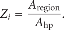
Using (2), the area ratios for the evaporator, adiabatic section, and condenser can be found as the heating area ratio, Zevap, the adiabatic area ratio, Zadia, and the condenser area ratio, Zcond, respectively. The heating-to-cooling ratio,

All of these heating and cooling parameters for the current investigation are summarized in Table 1.
Parameters describing the heating and cooling conditions investigated.

Thirteen Type-T thermocouples were placed on the opposite, insulated side of the 3D FP-OHP to allow for perfect heating and cooling contact. These thermocouple locations are shown in Figure 3. It should be noted that the thermocouples assigned to describe temperatures in the evaporator varied between spot-heating and rectangular-heating. Table 2 summarizes all of the evaporator and condenser thermocouple designations for each heating condition. Temperature measurements were collected at a sampling rate of 100 Hz using a National Instruments SCXI-1600 data acquisition (DAQ) system and data was imported into a computer utilizing data collection software. Heat input into the heating elements was controlled using a variable autotransformer and digital multimeter (DMM). In order to verify the actual heat input, the average current and voltage across the heating elements were measured using the DAQ system equipped with a shunt resistor set-up. Heat input was increased in a stepwise fashion in increments of 10 W or 20 W, and transient and steady state data collection periods were performed for each heat input. Sufficient time was allowed after each new heat input to allow the heat pipe to thermally respond and reach steady-state. The steady-state data collection periods typically had durations of 3–5 minutes. Experiments ceased when either the maximum evaporator temperature neared
Designation of thermocouples for each 3D FP-OHP experiment.

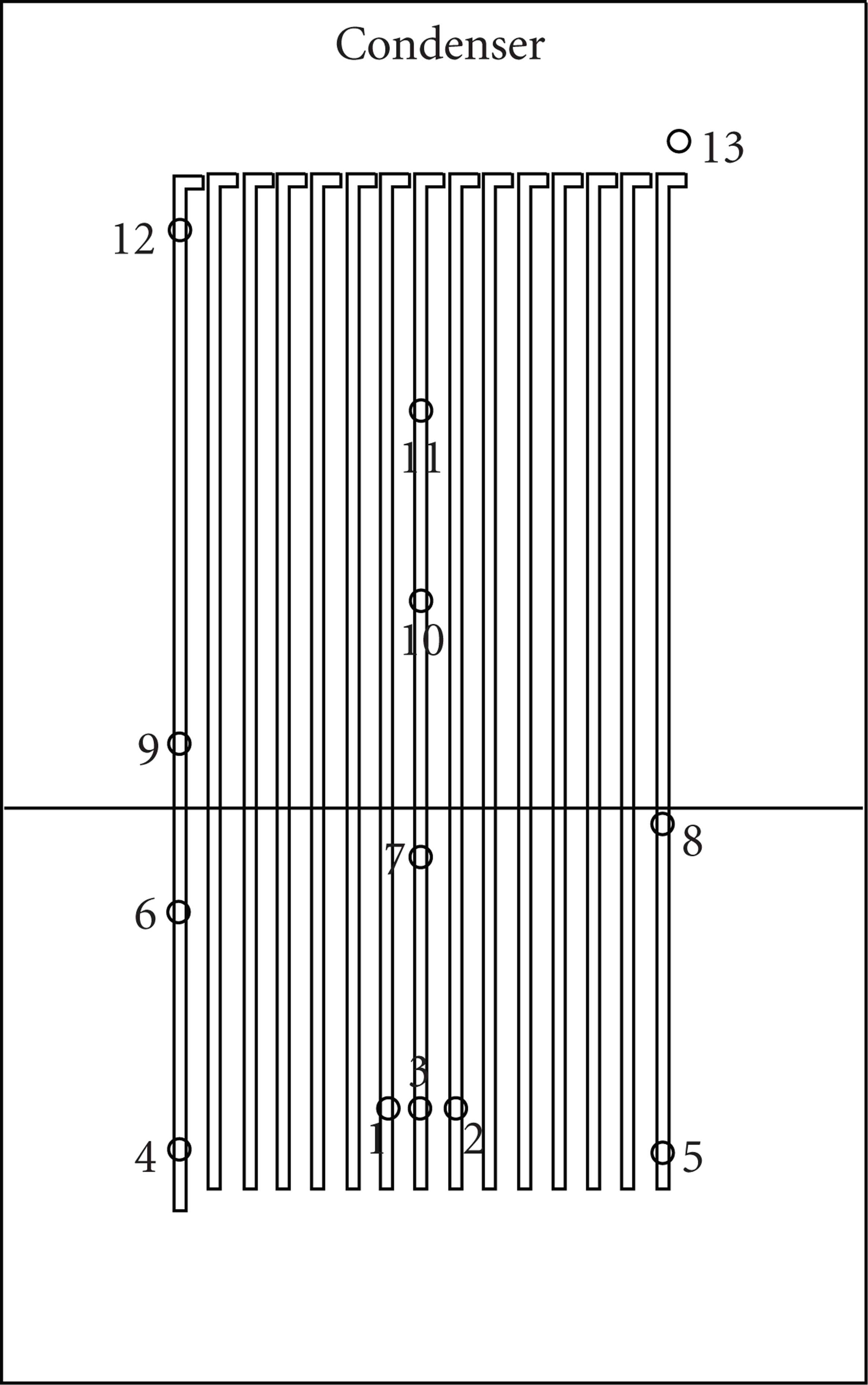
Thermocouple locations on one side of 3D FP-OHP.
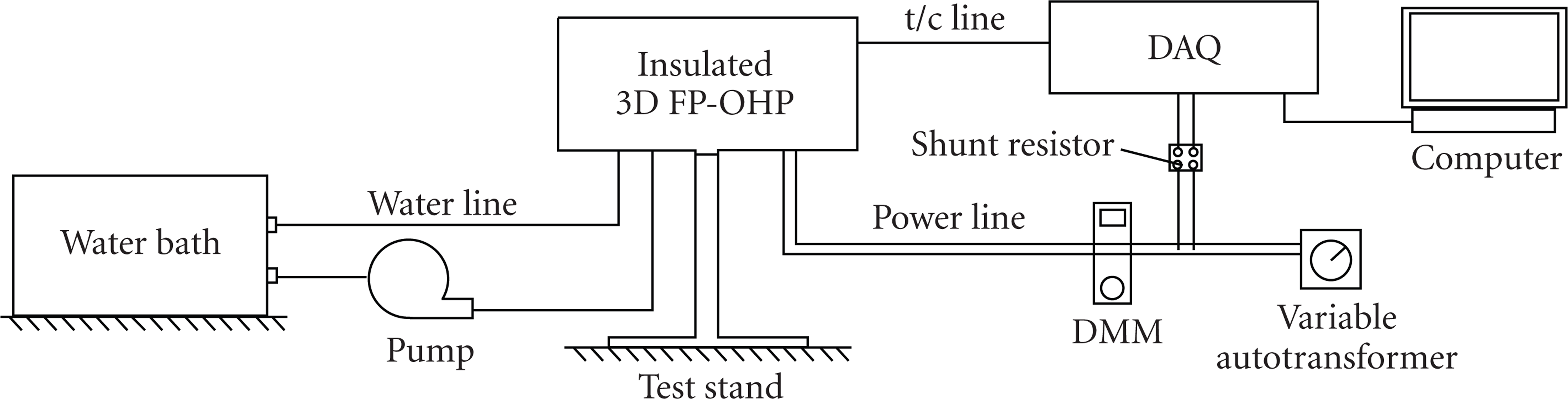
Schematic of experimental set-up.
Visual data was collected using real-time neutron imaging at the Center for Neutron Research at the National Institute of Standards and Technology (NIST) [10]. The set-up for visualizing the 3D FP-OHP during the spot-heating condition was similar to test set-ups previously reported [9, 11]. The thermal data collected during the neutron radiography experiments is not presented in the current study.
4. Experimental Results
The steady-state, average temperature difference across the 3D FP-OHP,

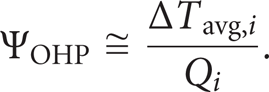
Then, for a given heat input, the thermal resistance of the 3D FP-OHP, ΨOHP, was calculated using
Figures 5 and 6 show the thermal resistance of the 3D FP-OHP at the various heating conditions for both cooling temperatures and all heating areas. It may be seen that the thermal resistance generally decreases with heat input for all heating conditions and both cooling temperatures and that lower thermal resistances are achieved while using the higher cooling temperature of

Thermal resistance versus heat input at a

Thermal resistance versus heat input at a
Figures 7 and 8 show the effect of heating area on the average evaporator temperature for the 3D FP-OHP. It was found that the average evaporator temperature increased almost linearly with heat input. At heat inputs over 60 W, the average evaporator temperature was consistently higher during spot heating. For rectangular-heating, the evaporator temperatures were about the same, until at higher heat inputs, AM heating provided lower evaporator temperatures. For a cooling temperature of

Average evaporator temperature versus heat input at a

Average evaporator temperature versus heat input at a
In order to understand the effect of heating area on the overall functionality of the 3D FP-OHP, the steady-state temperature, or thermal, oscillations that occurred in both the condenser and evaporator for all heating conditions were observed. Figures 9–11 provide the steady-state thermal oscillations at all thermocouple locations, for all three heating conditions, at a cooling temperature of

Steady-state temperature distribution versus time for CPM heating at 160.15 W at a

Steady-state temperature distribution versus time for AM heating at 161.58 W at a

Steady-state temperature distribution versus time for spot heating at 160.18 W at a

Standard deviation of neutron images for 3D FP-OHP at a heat input of 80 W and cooling temperature of
It may be seen from Figure 12 that during localized heating of the 3D FP-OHP, internal fluid activity occurred within a “bottle-shaped” region that was centered around the heating region on where only a portion of the internal channels participated while the outermost channels remained stagnant. As heat input increased, the width of this bottle-shaped distribution increased slightly while its height decreased. Thermal evidence of the bottle-shaped distribution is evidenced by the weak thermal oscillations of T4 and T5 and the lack of thermal oscillations of T6 and T8 as shown in Figure 11. The fact that channels located away from the evaporator were participating indicates the 3D FP-OHP's ability to distribute load of the heat flux and create an “effective” evaporator area.
In order to more accurately compare the thermal oscillations that occurred for each heating condition, the standard deviation of thermal oscillations about the average temperature for each thermocouple location was found by
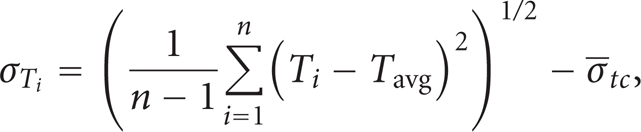
where n is the number of data points collected for the steady-state collection period. It should be noted that the average standard deviation for a thermocouple in the absence of heat input, or thermocouple “noise” (

respectively. The difference between the average standard deviations of thermal oscillations for the evaporator and condenser is then defined by

Equations (6)–(8) may then be used to measure the “amplitudes” of the thermal oscillations. It was found that the overall amplitude of thermal oscillations increased as the heating area decreased. Furthermore, the regional difference in thermal oscillations,

Difference in the average, regional standard deviations in thermal oscillations at a cooling temperature of
It may be seen from Figure 13 that the

Thermal resistance versus average standard deviation for thermal oscillations in the condenser for all heating conditions and cooling temperatures.
5. Conclusions
The 3D FP-OHP performed favorably while being locally heated and was shown to manage heat fluxes over 100 W/cm2 at cooling temperatures of
Using the average standard deviation of temperature measurements about the respective, local mean temperature, it was found that the amplitude of steady-state thermal oscillations in the evaporator increased with heat input and reduced heating area. In addition, the difference between the amplitudes of thermal oscillations in the evaporator and condenser increased with heat input and reduction in heating area. It was also found that the thermal resistance had an inverse relationship with the amplitude of thermal oscillations in the condenser.
Using neutron radiography, it was found that nonoscillating, stagnant liquid columns existed within channels located on the outer edges of the heat pipe during spot-heating of the 3D FP-OHP and that a bottle-shaped distribution of active fluid was present. Hence, not all interior OHP channels participated during localized heating, and the 3D FP-OHP functioned on a partial-hydrodynamic basis which resulted in an increase in thermal resistance. Hence, for highly localized heating applications, the FP-OHP's overall width should be minimized. There may also be a limiting heating area as a result of the number of channels in contact with the heating source. Hence, it is wise to minimize the wall thickness between channels to increase the channel density for high heat flux applications.
Footnotes
Nomenclature
Greek Symbols
Subscripts
Acknowledgments
The work presented in this article was supported by the Office of Naval Research Grant no. N00014-06-1-1119, under the direction of Dr. Mark Spector, and the DARPA TGP program under the direction of Dr. Tom Kenny. The authors acknowledge the support of the National Institute of Standards and Technology, U.S. Department of Commerce, in providing the neutron research facilities used in this work.