
Abstract
Force control of parallel robots with rotational degrees of freedom through impedance algorithms is considerably influenced by the representation method of the end-effector orientation. Using the natural invariants of the rotation matrix and the angular velocity vector in the impedance control law has some theoretical advantages, which derive from the Euclidean-geometric meaning of these entities. These benefits are particularly evident in case of robotic architectures with three rotational degrees of freedom (serial or parallel wrists with spherical motion). The behaviour of a 3-CPU parallel robot controlled by an impedance algorithm based on this concepts is assessed through multibody simulations, and the results confirm the effectiveness of the proposed approach.
1. Introduction
Several robotic applications involve the control of the interaction forces between end-effector and external environment; the control laws that can fulfil this requirement can be divided into two families: hybrid position/force control algorithms and impedance control algorithms. These two approaches have been widely discussed and compared in the scientific literature during the last decades, in particular with reference to serial kinematics [1–7].
In the last years the industrial interest about parallel robots (parallel kinematics machines, PKMs) is growing; mass-produced parallel manipulators are widely used especially in two categories of applications:
fast speed pick-and-place tasks with small payloads; in this case high-speed, lightweight parallel robots are adopted for their excellent dynamic performances, due to the low moving masses (e.g., the FlexPicker IRB340 by ABB based on the Delta kinematics [8]);
machining or assembly tasks characterized by high forces, which requires high structural stiffness and positioning accuracy; in this case high-stiffness PKMs (e.g., the F-200iB by Fanuc based on the Gough-Stewart kinematics [9, 10] or the Tricept by Neos Robotics AB) [11]) offer a high ratio between maximum payload/force and robot mass.
In most cases, parallel robots are position-controlled; nevertheless, the scientific and industrial interest about force-controlled PKMs is growing, even if only a few works on the subject are presently available, probably due to the fact that PKMs are relatively new architectures, characterised by quite complex kinematic and dynamic models [12–14]. In particular, the use of impedance-controlled parallel robots [15–18] is an effective solution: the moving masses of PKMs are limited, because the actuators are usually fixed to the ground, and then it is possible to realise the desired stiffness-damping behaviour neglecting the compensations of the inertial terms.
One of the major problems in the synthesis of a suitable impedance control law (both for serial and parallel robots) is the definition of the rotational stiffness, which is strictly related to the representation method for the end-effector orientation [19]. While the position of a point in space can be easily defined by a three-dimensional vector, there are many mathematical tools to represent the orientation of a rigid body in space [20, 21] and this influences the resulting impedance control law. In the following of the paper this aspect will be discussed with reference to simulation results involving an impedance-controlled 3-CPU parallel robotic wrist.
2. Representation of the End-Effector Orientation
Probably, the most common method to describe the orientation of a rigid body is the use of the Euler angles; nevertheless, this method has many drawbacks [22, 23]:
there are 12 different sets of Euler angles, and the choice of a set influences arbitrarily the control algorithm;
there are representation singularities (configurations defined by nonunique values of Euler angles), and in these singularity loci it is impossible to describe an arbitrary angular velocity as function of the Euler angles time derivatives.
Some researchers tried to overcome these limitations by using a modified set of Euler angles that avoid singularities [24] or the so-called Euler parameters, a 4-dimensional vector of invariants that are not geometric entities [25].
Another possible representation of the orientation is the 3 × 3 rotation matrix, but its nine elements are not independent and an impedance algorithm based on three independent rotation matrix elements is poor of geometrical meaning.
An arbitrary rigid body rotation is uniquely defined by the axis of rotation (represented by the unit vector
In [26] the use of the frame-invariant vector

In an impedance algorithm the vector

This is a very important propriety of the vector
3. The 3-CPU Parallel Architecture
In the 3-

The 3-CPU parallel architecture.

Leg of the CPU parallel architecture.
The axes of the cylindrical joints

The direct and inverse kinematics of the robot make the forward and backward connections between the internal coordinates and the relative rotation of the frame
The choice of the three external coordinates influences the impedance control law; in the following, two possible sets of external coordinates are considered:
the set of Euler angles α, β γ corresponding to three subsequent rotations along the axes u, v, w that represent the overall relative rotation between
the three components of the vector
Independently of the selected set of external coordinates, the direct kinematic problem admits up to 8 solutions, while the solution of the inverse kinematics is single [27]. The choice of the external coordinates determines the consequent Jacobian matrix: deriving the two possible sets of inverse kinematics equations, two alternative analytical Jacobian matrices can be found:
the analytical Jacobian matrix

the analytical Jacobian matrix
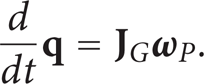
The geometric Jacobian
It is easy to demonstrate, by using (2), (5), and (6), that if θ tend to zero, the Jacobian matrices

4. Impedance Control Algorithm
The basic concept of impedance control is that the robot end-effector, subject to external forces, follows a trajectory with a predetermined spatial compliance [28, 29]; this compliance, which influences the end-effector dynamic behaviour, is defined by the stiffness matrix
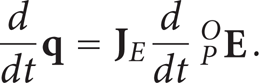
The actual position of the end-effector can be represented alternatively by the external coordinates vectors

where [27]


where [27]:

In the control laws (8) and (10) one has the following:
Let us note that in the control law (10) the damping term is not based on the derivatives of the external coordinates but on the angular velocity vector. The matrices

where
In the following section, the control laws (8) and (10) will be compared by means of multibody simulation, to show the advantages of the second control law, due to the geometric properties of the vector
5. Simulation Results
The impedance control laws (8) and (10) have been applied to a 3-CPU parallel robot with the geometric and inertial parameters shown in Table 1. Since the two links of each leg rotate only about the corresponding cylindrical joint axis, only the moments of inertia with respect to this direction are reported; the universal joints crosses can be considered lumped masses concentrated in the corresponding universal joint centres.
Geometric and inertial properties of the considered 3-CPU mechanism.

Case Study A. In the case study A, starting from the initial condition with the coordinate frames P and O coincident, a moment

The value of the desired isotropic stiffness (k = 100 Nmm/rad) is arbitrary; the value of the isotropic damping coefficient is selected using an heuristic approach, considering each rotational direction as a linear inertia-torsional spring-torsional damper system with a damping coefficient

where
The rotational behaviour of the robot about the three directions can be compared with three decoupled second-order inertia-rotational spring-rotational damper systems, characterized by the following linear differential equations:
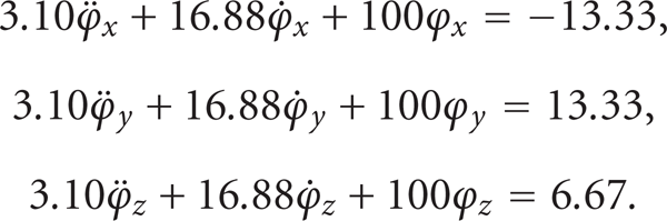
For these three decoupled systems one has the following:
the inertia of the stiffness and damping coefficients are equal to the isotropic stiffness and damping coefficients k and c; the applied moments are the three components of the moment
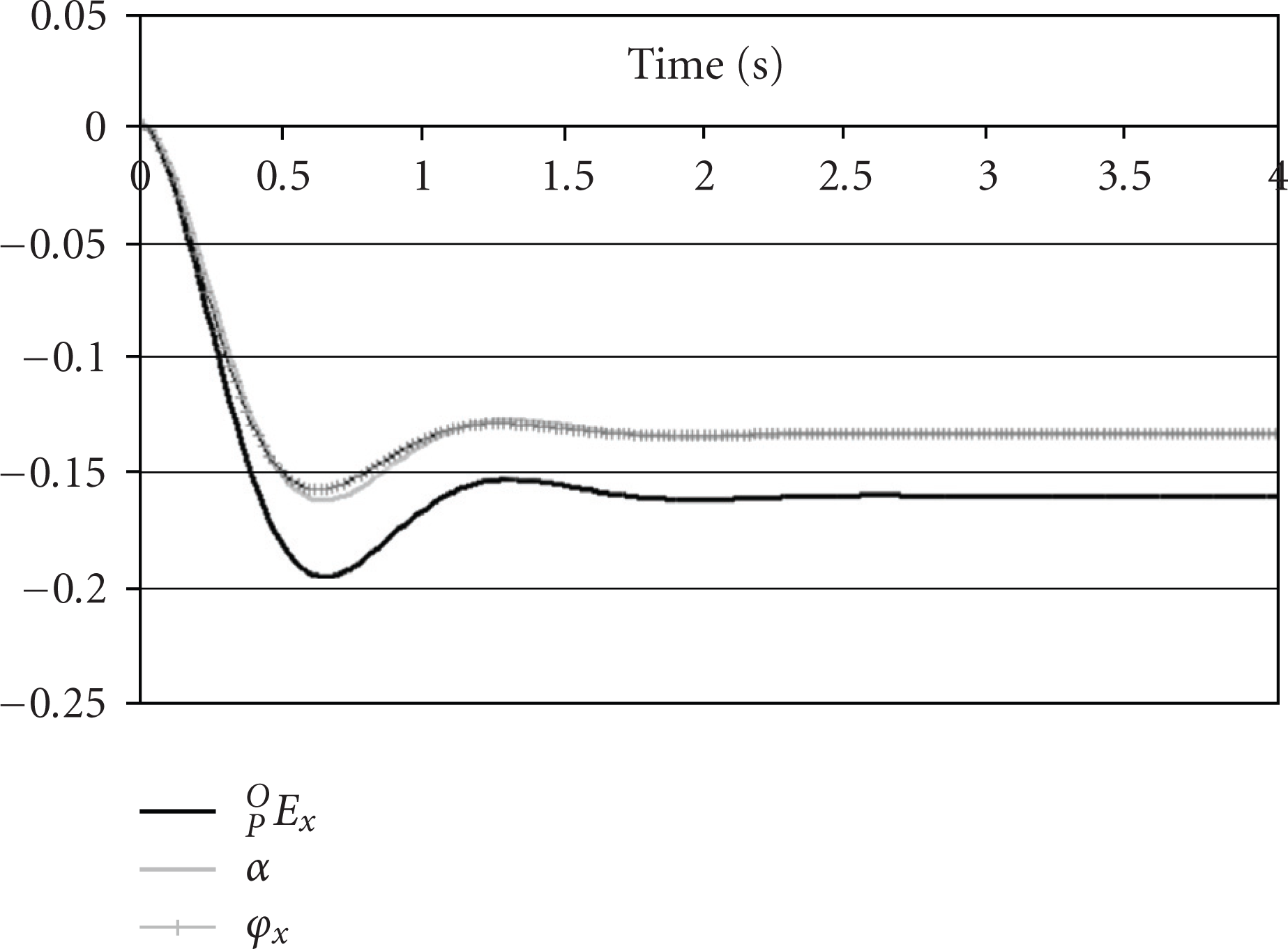
Figures 3, 4 and 5 show the rotational behaviour of the robot controlled by the law (8), based on the analytical Jacobian matrix, in comparison with the three decoupled systems (15); in these graphs the end-effector orientation is represented both by the components of the vector
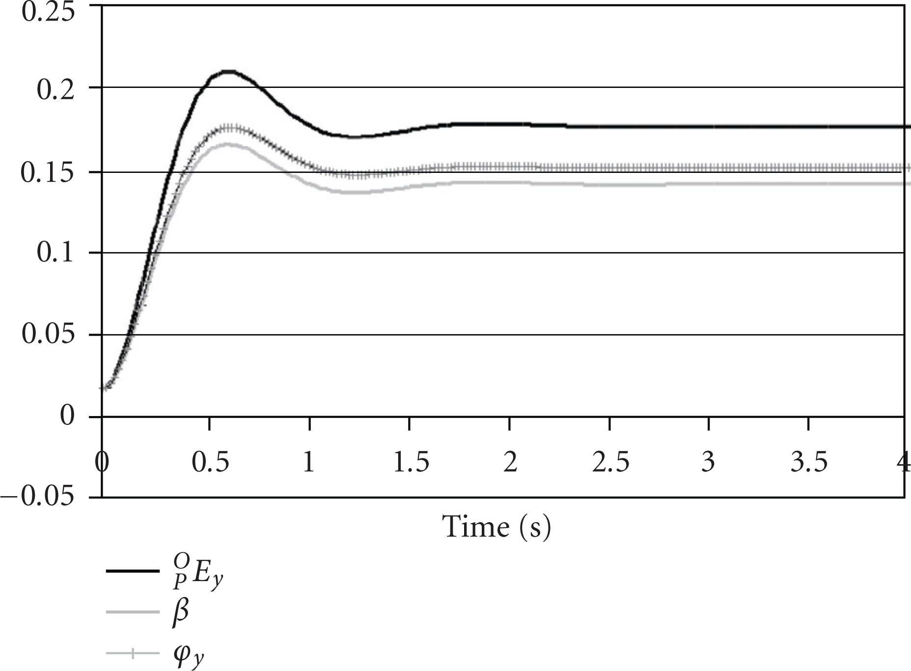
Both the control laws apply the isotropic stiffness and damping expressed by the matrices (13), but only the geometric control law (10) realizes an isotropic behaviour: in final steady state the end-effector rotation is
Moreover, it is possible to note that using the geometric control law (10) the time histories of the three components of
Comparison of
Comparison of

Comparison of

Comparison of

Comparison of

Comparison of
Case Study B. In the case study B, starting form the initial condition with the coordinate frames P and O coincident, a moment

which corresponds to the rotation matrix:

The principal rotational stiffness and damping matrices are
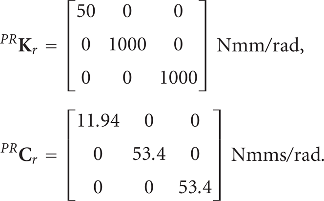
The matrix
The rotational behaviour of the robot about the three principal directions is compared with three decoupled second-order inertia-rotational spring-rotational damper systems loaded by the components of the external moment
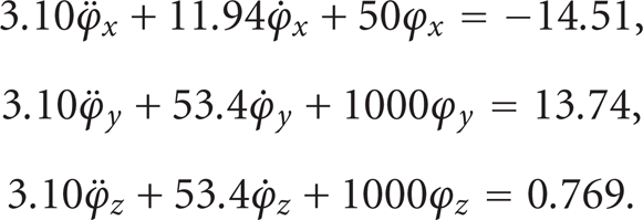
Figures 9, 10 and 11 show the behaviour of the robot controlled by the law (8), based on the analytical Jacobian matrix, in comparison with the three decoupled systems (19); Figures 12, 13 and 14 show the same comparison, but applying the law (10), based on the geometric Jacobian matrix. In these graphs the end-effector orientation with respect to the principal stiffness and damping reference frame is represented both by the components of the vector
It is possible to note that using the control law (8) the rotational behaviour of the robot is remarkably different from the decoupled systems; on the contrary, using the control law (10) the time histories of the three components of the vector
the relative difference between the relative difference between the relative difference between
All the relative differences tend to zero in steady state. These results show that the control law (10) imposes successfully the rotational compliance about the three principal axes, and is capable of effectively constrain the rotation direction; the robot behaviour is almost decoupled in the three rotation directions and similar to a linear three-degree-of-freedom second-order system. Let us note that compete decoupling of the robot dynamic behaviour could be obtained by introducing the model-based compensation of the inertial terms [30], but this increases remarkably the computational burden without significant benefits.

Comparison of

Comparison of

Comparison of

Comparison of

Comparison of

Comparison of
6. Conclusions
The vector
If the Euler angles are used as external coordinates, the kinematics is characterized by the analytical Jacobian matrix
This important geometric property has relevant consequences on the behaviour of the resulting impedance control; to show that, the behaviours of the 3-CPU parallel robot controlled by two different impedance algorithms, based on the Jacobian matrices
The simulation results show that only the geometric Jacobian-based impedance control law allows to impose properly isotropic and nonisotropic end-effector stiffness and damping; moreover, the end-effector rotations along the three principal stiffness/damping directions are almost decoupled and similar to linear second-order systems, without the need of the model-based compensation of the inertial terms, which is computationally heavy.
For all of these reasons, using the components of the vector
The dynamic performance of a robot controlled by the proposed algorithm depends on the inertial properties, on the features of the actuators, and on the stiffness and damping matrices; adopting a proper mechanical design in combination with actuators characterized by high force/torque it is possible to impose high values of control stiffness and consequently to perform high frequency motion.
Although the main objective of impedance control is to obtain rotational compliance in one or more directions, high rotational positioning accuracy can be obtained in the remaining directions by imposing high values of the corresponding elements of the stiffness matrix; obviously, in the real implementation the maximum accuracy is limited by the mechanical stiffness and by the accuracy of the sensors.
In the following of the research, the proposed control algorithms will be experimentally tested on the 3-CPU rotational parallel robot prototype shown in Figure 15 [31].
3-CPU parallel robot prototype.
