
Abstract
We have formulated a geometric non-linear mathematical-physical model of the snap-through of the system of a thin-walled shallow bimetallic translation shell in a homogenous temperature field according to the theory of large displacements, moderate rotations, and small strains of the shell element. The model enables the calculation of the geometric conditions, of shallow translation shells, due to the influences of temperature and mechanical loads. The results are based on the numeric solution of a non-linear system of partial differential equations with boundary conditions according to the finite difference method.
1. Introduction
The development of science has enabled the manufacture of different technical devices, from relatively simple mechanisms to very complex machines that humanity uses in technological processes for transforming material goods. Although by their shape, purpose, and build these modern devices are quite diverse, due to the importance of their uninterrupted, reliable work, and their value, a demand exists for the protection of these devices from different overheating. It is especially necessary with machines and devices that transform one form of energy into another to provide reliable protection from temperature overheating. Therefore, it is of essential importance for the safe working of the machine that the heat produced during its operation is effectively diverted into the surroundings. Apart from the technical features of cooling, the transfer of heat from the machine into the surroundings is also dependent on the characteristics of the work process and the temperature of the surroundings. In certain circumstances, the temperature of the machine can exceed the maximum-allowed value for its safe operation, in which case temperature overheating of the machine occurs. For safety, it is necessary to install safety elements that deactivate the machine if the temperature reaches the maximum-allowed value. Due to their reliability, bimetallic line and plane construction elements have been proven for the protection against temperature overheating. The working of these elements is based on a known physical phenomenon that bodies expand with the increase of temperature. The relative change of the body's length du/dx in the direction of side x is directly proportional to the change in temperature:

The proportional coefficient α in (1) is a linear temperature coefficient of the longitudinal expansion and is dependent on the type of material. If we assume that bodies expand isotropically, equally in all directions, then the temperature coefficients of the longitudinal expansions in separate directions x, y, and z are equal:

In (2) u, v, and w denote the elements of the displacement vector. In the case of bimetallic bodies from two materials that have different temperature expansion coefficients the expansions due to temperature changes are not isotropic.
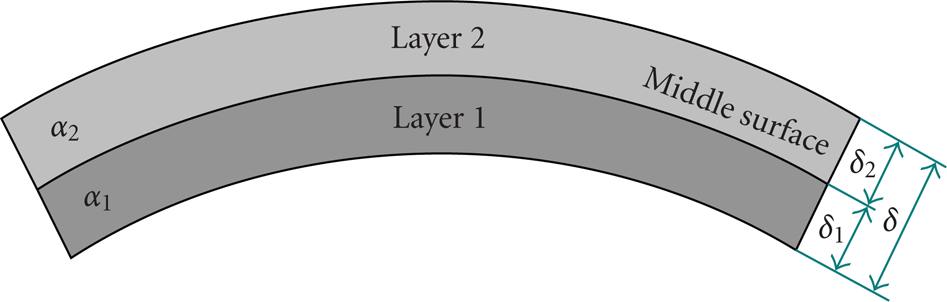
In Figure 1 a bimetallic strip of length a and thickness δ is shown.

Bimetallic strip before temperature load.
The lower layer 1 is manufactured from a material with a linear temperature expansion coefficient of α1, while the top layer 2 is manufactured from a material with an expansion coefficient α2. If the expansion coefficients are equal α1 = α2, the temperature expansions and contractions are isotropic, which is why the shape of the strip remains the same even after the deformation. In this case, only the surface area of the bimetallic strip is increased by

where S0 stands for the area of the strip before the deformation.
When the expansion coefficients are different, α1≠α2 curving appears in the strip. The strip curves into a convex shape if α1>α2, and into a concave shape if α1┼α2 as in Figure 2.
Bimetallic strip after temperature load.
With a suitable technical assembly, we can connect a bimetallic construction element with electric contacts and create a so-called “thermal switch.” Displacements in the bimetallic element that occur due to a combination of temperature and mechanical load will activate or deactivate the apparatus depending on the temperature T. For this, it is of course necessary to know the functional connection between displacements and load of the bimetallic construction element. This connection is, apart from the material, also dependent on the geometric characteristics of the bimetal as, for instance, the line bimetallic construction elements, when compared to plane elements, will react with a different tension and deformation state under temperature load. Above all, in practice the differences in the stability conditions are important. Thin and shallow bimetallic shells with suitable material and geometric characteristics have the attribute that at certain temperatures they snap-through into a new state of equilibrium. The result of this rapid snap-through of the bimetallic shell as the element in a thermal switch is the immediate disconnection of electrical current and the deactivation of the machine. The snap-through of the bimetallic shell is a dynamic phenomenon that lasts for a brief moment; as a result, it prevents harmful sparks and fusing of electrical contacts and prolongs the life span of the thermal switch.
D.V. Panov, S. Timoshenko, E. V. Videgren, W. H. Witrick, B. Aggarwala, E. Saibel, Liu Ren Huai, F. Kosel, M. Batista, R. Drole, M. Jakomin, and certain other authors have engaged in research on bimetallic shell elements in a homogenous temperature field. Timoshenko [1] researched the problem of stability of bimetallic strips and plates. Witrick [2] researched the problem of stability of shallow rotational axi-symmetric spherical shells during heating. B. Aggarwala and E. Saibel researched the stability of shallow spherical shells [3]. Liu Ren Huai [4] debated with approximative methods the snap-through phenomenon of an open bimetallic shell. Kosel et al. [5], Kosel and Jakomin [6], and Batista and Kosel [7] researched analytically and numerically the stability conditions of rotational axi-symmetric shells with and without an opening in the apex.
This time we are discussing the stress and deformation conditions for a thin double curved translation bimetallic shell, which apart from temperature is additionally burdened with an equally distributed force along the surface of the shell. Due to the different curvature along the longitudinal and transversal directions different conditions between the so-called upper and lower snap-through are possible in the translation shells.
In deriving the nonlinear mathematical model for the snap-through of a bimetallic translation shell, we presumed small strains and moderate rotations of the shell element. We also took into consideration nonlinear terms in the deformation tensor, while we placed equilibrium equations on the deformed part of the bimetallic shell.
2. Geometry of the System
We define the middle plane of the bimetallic shell in an undeformed state, Figure 3, with the position vector

Middle plane of the undeformed bimetallic shell in the rectangular Lagrange Coordinate System.
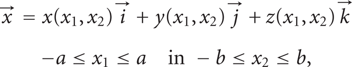
where x1 and x2 are the orthogonal parametric variables while
We can also define any given point on the middle plane of the undeformed shell in a natural curvilinear coordinate system with orthogonal curvilinear coordinates s1(x1,x2) and s2(x1,x2); see Figure 3. The unit vectors

Basis unit vectors on an undeformed shell element.

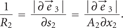
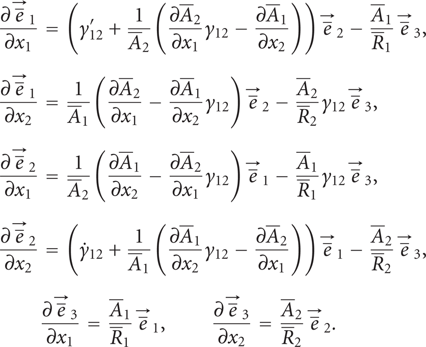
Partial derivatives of the orthogonal unit vectors
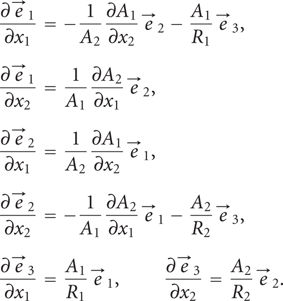
In (6) for partial vector derivatives with respect to parametric variables x1 and x2, the flexion curvatures of the shell's middle plane are denoted with 1/R1 and 1/R2:

A special and in practice very common type of shell is the so-called translation shell; see Figure 5. We construct the middle plane of the translation shell with the translation of the secondary curve y2(x2) along the primary plane curve y1(x1) so that at the intersection point of both curves the tangent vectors

Construction of the middle plane of a translation shell.

With adding two equally thick layers δ/2 that have a different linear temperature expansion α1 and α2 orthogonally to the middle plane of a translation shell, that is, in the direction of the unit vectors

where ψ is the meridian angle:


if for the partial derivatives with respect to variables x1 and x2 we introduce the denotations:

With (12) and (14) the position vector

With shallow shells, the meridian angle ψ(x1) in the interval
due to which we can note that

For shallow translation shells with these simplifications we have the following:


3. Equilibrium Equations
Let us observe the bimetallic shell which apart from temperature is additionally burdened with an equally distributed force along the upper surface of the shell. Due to the external temperature and force exerted on the shell, a stressed state occurs within the shell that results in the deformation of the shell. Upon deformation and displacements of the shell the curves s1(x1,x2) and s2(x1,x2) also deform and alter into the curves
In the elementary part of the deformed shell that is created by cutting the shell in the direction of the curvilinear coordinates

Forces and moments per unit of length in the middle plane of a deformed shell.
In a stationary state when the temperature T and the force acting on the shell do not change, the conditions of a mechanical equilibrium apply


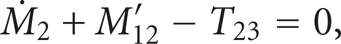
Based on Figure 6 the equation for the equilibrium of forces (23) is, if we disregard the force of the shell's weight, which is small when compared to the other forces,
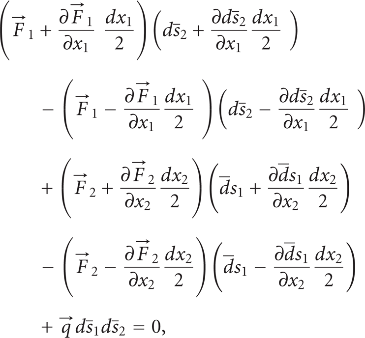
and after arranging:

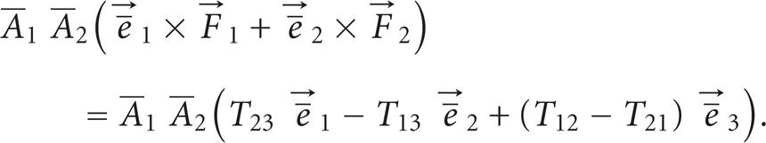
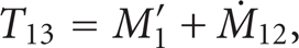
Similarly (24) describes the equilibrium of moments in a deformed shell around the point O in Figure 6 when we ignore differential terms of the higher orders:

from where after arranging follows

where

In (27), (28), and (29),

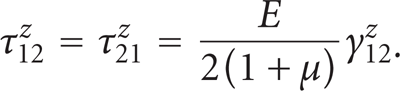
The absolute value of the total differential of the position vector
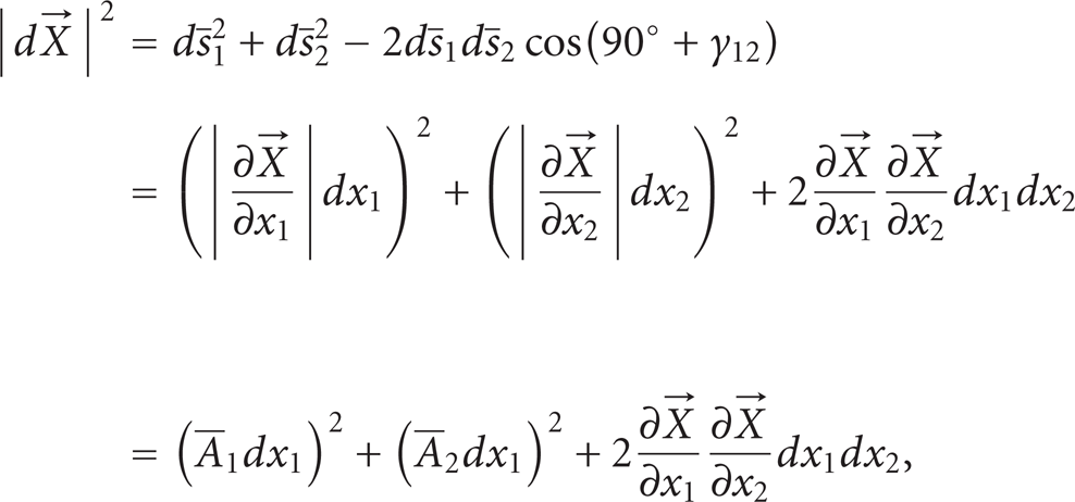
from which follows

if in (32) one of the parametric variables remains constant. The angle change between the curves
The forces
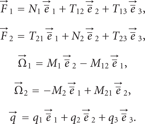
By considering (33), the equations for the equilibrium of forces (26) and moments (28) are

And after this when we express the forces

Both equilibrium equations are in vector form. For a record in the component form, that is, in the direction of the unit vectors
The equilibrium of forces acting in the observed shell element can be written down in the component form by three equations when (37) is taken into account.
In the direction of the unit vector

in the direction of the unit vector

and in the direction of the unit vector

In an analogue method we also write three more equations for the equilibrium of moments on the observed shell element.
In the direction of the unit vector
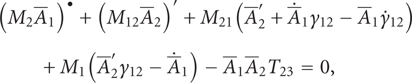
in the direction of the unit vector

and in the direction of the unit vector

Fifteen unknown magnitudes act within the system of six partial equations for defining the equilibrium of forces and moments in a deformed part of the shell ((38) to (43)): Lamé's parameters
4. Forces and Moments Per Unit of Length
It is consequent from (34) that N1 and N2 are normal forces per unit of length in the directions of the unit vectors
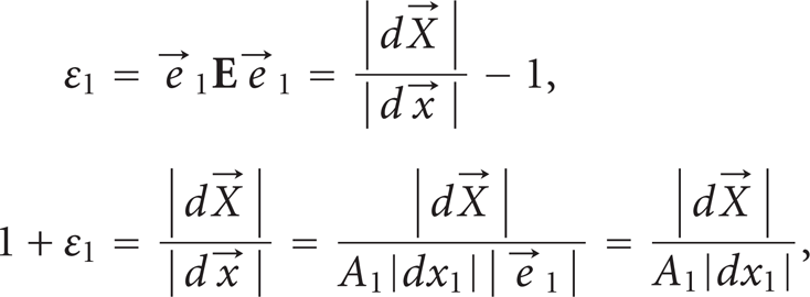
We express the intensity of forces and moments per unit of length with definite integrals, where σ1 and σ2 are normal stresses in the direction of the unit vectors

5. Kinematic Equations
We will express Lamé's parameters

In (45) the Green Lagrange deformation tensor [10] is denoted with

where

Connection between the Lagrange and Euler Coordinate System.

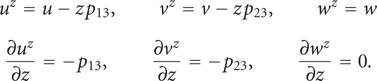
If we insert
or

and in the same way when we insert

Since the strains of the shell must not exceed the limits of the material elasticity, we can introduce into the formation of the mathematical model a supposition that all strains according to the absolute value are much smaller than the number one:

which is why, when we take into consideration the approximation (21), we can record

The differential of the arc length

and in the same manner also:

With shells that are thin enough the ratio between the shell thickness and the radius of the curvature is relatively small compared to the number one:

due to which, when we take into consideration the shallowness of the shell and the small strains according to the suppositions (21) and (51), is then

6. The System of Thermoelastic Equations
The stresses that occur in a shell element from external mechanical and temperature loads are defined by Hook's law:
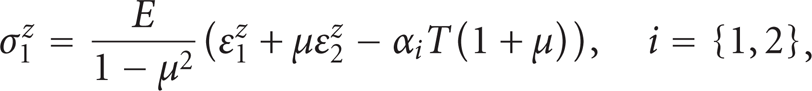

In the equations for stresses (57) and (58) the symbol T denotes the shell temperature load, which is the difference between the shell temperature T s and the reference shell temperature T r :

where we surmised that a reference shell temperature T r exists, with which the stress state in the entire shell region is equal to zero:

We will express the strains ε1,ε2, and γ12 in the middle plane of the shell element that act in the equations for stress and strain (57), (58), and (59) with the Green Lagrange deformation tensor (46).
The vector operator

The gradient of the displacement vector (i.e., displacement vector gradient)

The last three elements of the displacement vector gradient

Connection between displacement vector

We also find the connection between the unit vectors
The differential of the position vector
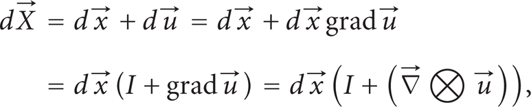
from which follows

where the symbol I denotes the tensor of the second order with the unit 1:

With this, the unit vectors

In case of small strains according to the supposition (51) and moderate rotations, up to approximately 20°, the components of the displacement vector gradient

due to which the components of the displacement vector gradient p11,p12,p21,p22, and p33 in comparison with the number 1 are disregarded. The error, we commit with this, amounts at most to 6 percent [10].
With these suppositions the unit vectors

The displacement vector

or in a component form:
With these equations

while the deformation tensor (46) is

The strains ε1,ε2, and γ12 in the middle plane of the shell are defined with the Green Lagrange deformation tensor (74). For calculating the stresses σ1
z
,σ2
z
, and τ12
z
it is necessary to know the strains ε1
z
,ε2
z
, and γ12
z
on the distance z from the middle plane in the direction of the unit vector
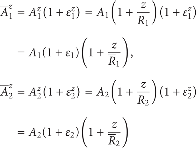
with the help of which the strains ε1 z and ε2 z are expressed as


We can also express the strains ε1,ε2 and γ12 outside the middle plane of the bimetallic shell with the deformation tensor


The comparison of (78) and (79) with (76) and (77) yields the following connections:

Now, in the equations for stress and strain (57), (58), and (59) we express the strains ε1 z ,ε2 z , and γ12 z with (78), (79), and (81), and with these values, we calculate the definite integrals (44) for forces and moments per unit of length. In this way we obtain
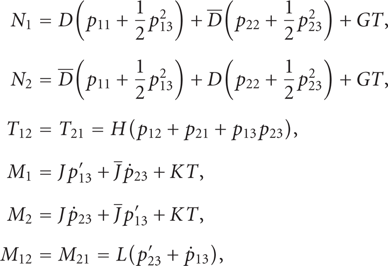
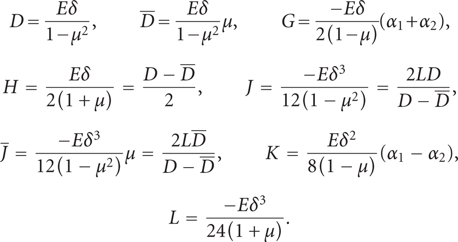
where
Given that according to the supposition (51), the strains on the shell are small, we can disregard in the equilibrium equations (38), (39), (40), (41), (42), and (43) not only the terms containing derivatives of Lamé's parameters


The reader should note that (90) is satisfied identically. When replacing in this equation the forces T12, T21 and moments M12M21 per unit of length by their expressions (44) and using (53) and (54) for differentials

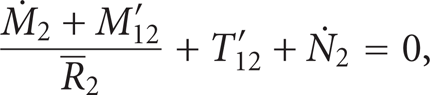
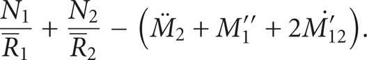
We express the forces T23 and T13 from the moment equilibrium equations (88) and (89):

and we insert them into (85), (86), and (87) for the equilibrium of forces. With this, the equilibrium equations for forces are:

With the forces and moments per unit of length in (83), (92), and (93) the equilibrium equations for forces (85), (86), and (87) expressed with the components of displacement vector gradient

We can finally also express the elements of the displacement vector gradient
In continuation, we will treat the most common forms of loads on bimetallic shells that we encounter in practice. Commonly, such shells are loaded with a homogenous temperature field and with a continuous equally distributed force per unit area

In this loaded case the equilibrium equations (97) are expressed with the displacements u, v, and w:

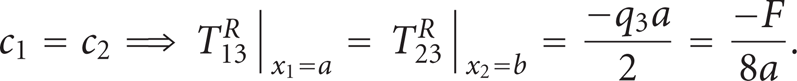
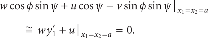
We complement the system of three nonlinear partial differential equations (99) with boundary conditions on all four edges of the bimetallic shell. We will treat a simply supported shell where the bending moments M1, M2, normal forces N1, N2, and longitudinal shear forces T12, T21 per unit of length at the edges of the shell at x1 = ±a and x2 = ±b are equal to zero, while the transversal shear forces per unit of length T13, T23 are dependent from external force. If the load on the shell

where c1 and c2 are constant values the boundary conditions are
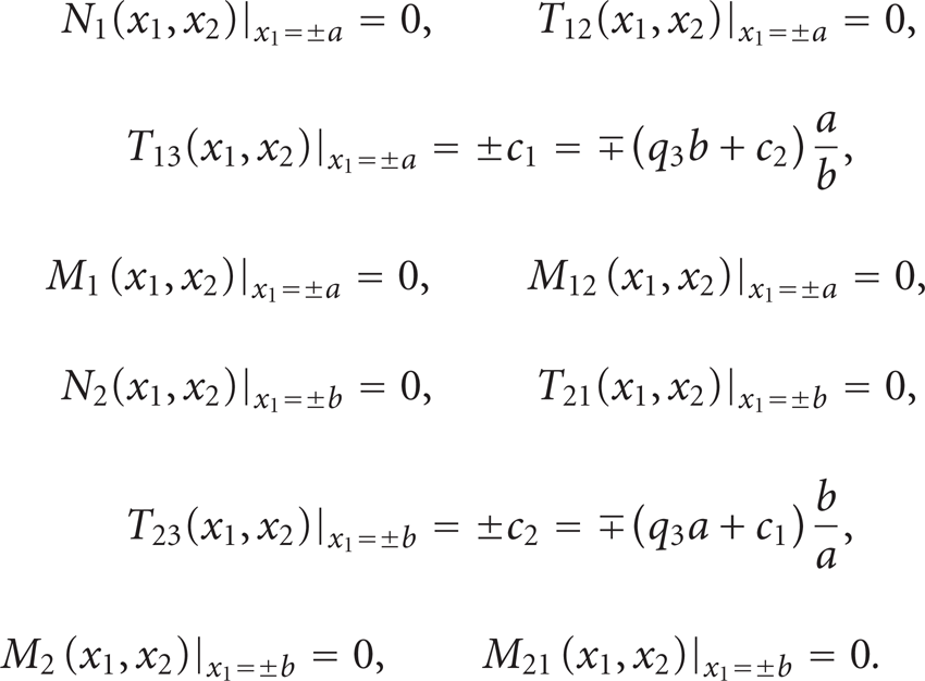
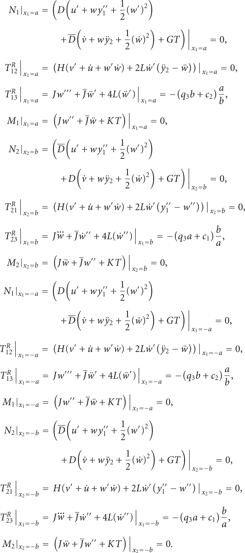
We express the transversal shear forces T12 and T21 and the torsion moments M12 and M21 on the edges of the shell with the so-called reduced transversal force T1 R and T2 R and in this manner reduce the number of boundary conditions on each contour of the shell by one condition [8]. With the reduced transversal force, the equations for the boundary conditions (101) are

If in the boundary conditions (102), the forces and moments per unit of length are expressed with the elements of the displacement vector gradient according to (83), and those with the elements of the displacement vector u,v and w in a matrix (73), the final form for boundary conditions is obtained:
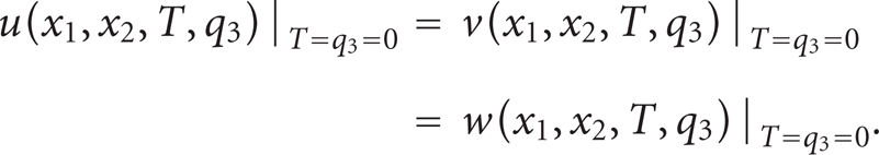
The system of three differential equations (99) together with the boundary conditions (103) defines the mechanical and stability characteristics of a simply supported thin and shallow bimetallic shell in a homogenous temperature field. It is also demonstrated that this system has symmetry. Namely, if the displacement vector

due to which, it is sufficient that we solve the system of equations only in one quadrant, for instance, in the region
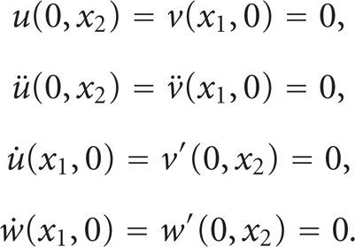
The remaining conditions on the edges of the shell at x1=a and x2=b are defined with unit forces and moments in the equations for boundary conditions (103).
7. The Numeric Solution to the System
We solved the system of nonlinear differential equations (99) with the appurtenant boundary conditions (103) and (105) by using a finite difference method [12] in the program package Mathematica 7.0.0. We substituted the partial derivatives with the central-difference approximation and solved the obtained algebraic system of nonlinear differential equations with the City Newton method on different loaded cases. For the translation curves, we took two equal parabolas:

The initial approximation for the displacement vector
Using the Newton-Raphson method [13], for finding successively better approximations to the zeroes of the system, displacements magnitudes u,v, and w are calculated. Then we repeat the procedure and calculate the displacements u,v and w in the direction of the unit vectors
We present the results for a simply supported shell loaded with a temperature T and with a force per unit area q3 that has the following material and geometric characteristics:

The middle plane of a shell free of any load with the characteristics in (108) is shown in Figure 9. For this case due to external force the following reactions appear on the shell edges:
We slowly heat up a shell that is loaded with an equally distributed force F= − 20 N along the upper surface of the shell. So the force per unit area equals q3 = −0,05 N/mm2. Let us observe the change in the relations of heights ξ in dependence of temperature T. Figure 10 shows the relationship between the temperature
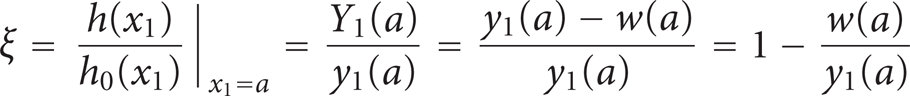
and the stability conditions during temperature and mechanical load of the bimetallic shell.

The initial geometry of an undeformed, temperature, and mechanical unburdened translation shell.

Function T=T(ξ) for the case of a translation shell that exhibits the phenomenon of snap-through of the system between points AB when heated and points CD when cooled.
Due to equally distributed force F along the upper surface S of the shell S=4a2 the initial relation of heights ξ, which for an unburdened shell amounts to ξ=1, is reduced. By heating the shell, that relation further decreases to the point A(0.21,81.8) where the shell has an unstable equilibrium position and the so-called upper snap-through at the temperature Tp1 (Figures 10 and 11). After the upper snap-through the shell occupies a stable equilibrium position at point B(− 0.43,81,8). In the case of the shell cooling the relation of heights ξ increases to the point C(− 0.22,75.7) where an unstable equilibrium position again occurs. Consequently the shell has a lower snap-through and snaps to the point D(0.42,75.7) (Figures 10 and 12).
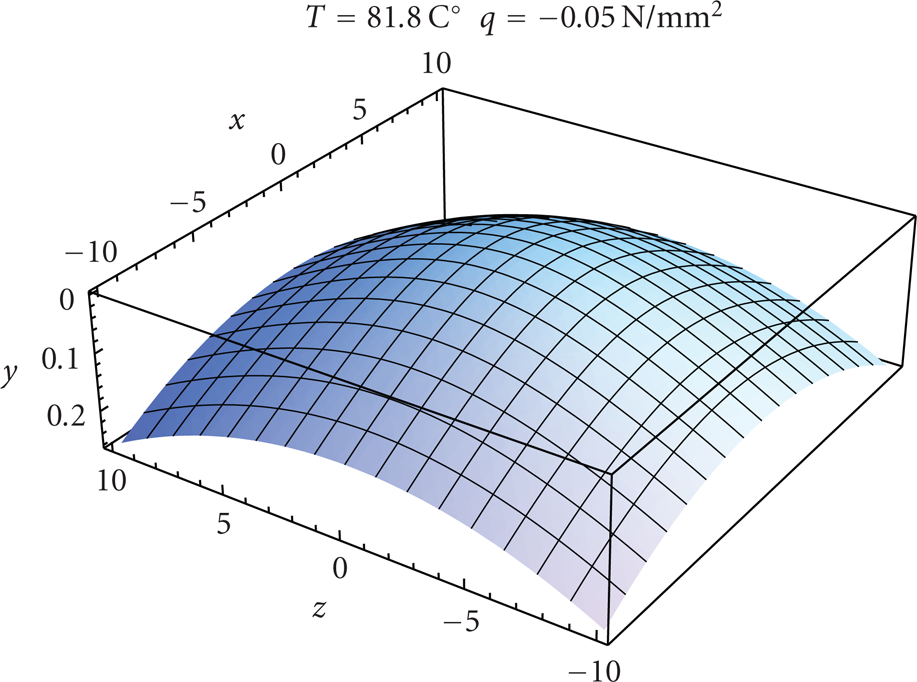
The geometry of a shell at the start of the upper snap-through.

The geometry of the shell at the start of the lower snap-through.
The stability curves in dependence from different mechanical loads q3 and temperature T for a shell with the geometric characteristics in (108) are shown in Figure 13. With the increase of force per unit area q3, the temperature of both snap-throughs Tp1 and Tp2 decreases.
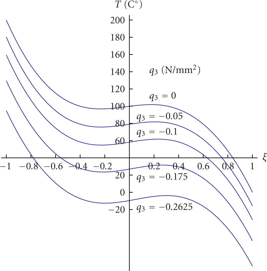
Stability curves for different load values q3.
With a strong enough force per unit area q3, the shell will snap-through without additional heating. With the interpolation of the snap-through temperature Tp1 in dependence from external loads q3 in Table 1, we have calculated, in the treated case, that the shell without additional heating snaps-through if loaded with an equally distributed force F= − 101.4 N along the upper surface of the shell, which amounts to a mechanical load of q3 = −0.2535 N/mm2.
The snap-through temperatures in dependence from the load q3 in case of an equal support on the shell edges.

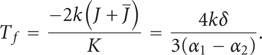
The flat state of the bimetallic shell occurs at the temperature T f . If the shell with two equal parabolic construction curves is loaded only with temperature T, then T f can be readily calculated from the boundary condition (103) for the bending moment M1. When the shell is completely flat, the displacement w is


from which the temperature T f of the flat shell follows
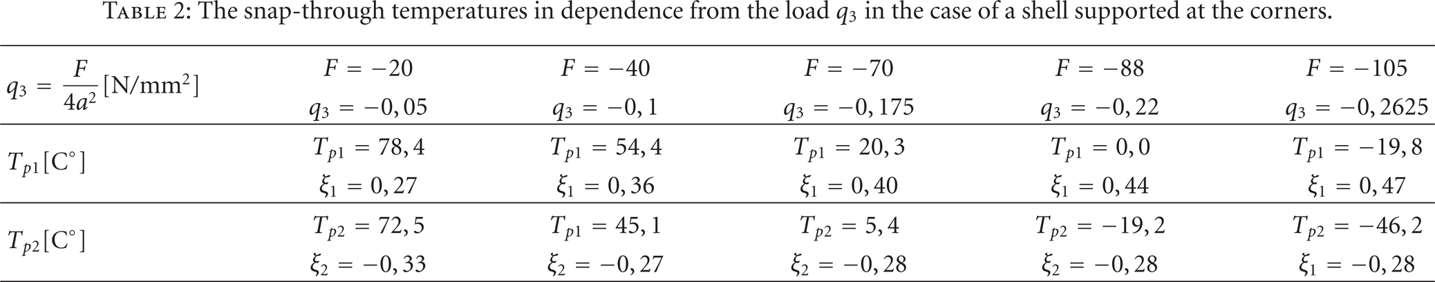
In continuation let us observe the shell loaded with temperature T and force per unit area q3 and let the outer force, equally distributed along the upper shell surface, be compensated at the four opposite corners of the simply supported bimetallic shell. In this example of load we solve the BVP defined with a system of differential equations (99) and boundary conditions (103) and (105). The reduced transversal shear forces per unit of length T13 R and T23 R in the boundary conditions (103) are
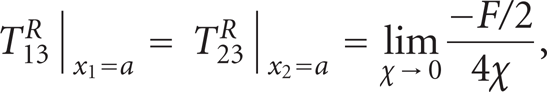
where
The snap-through temperatures in dependence from the load q3 in the case of a shell supported at the corners.
Let us also observe the case of the simply supported shell, which at its apex, at the point x1 = x2 = 0, is loaded with a concentrated force F. For this example of load it is necessary to place in the equilibrium equations (99):

The reduced transversal shear forces per unit of length T13 R and T23 R have values in (114). Parameter χ defines the region where the force F exerts and limits towards zero.
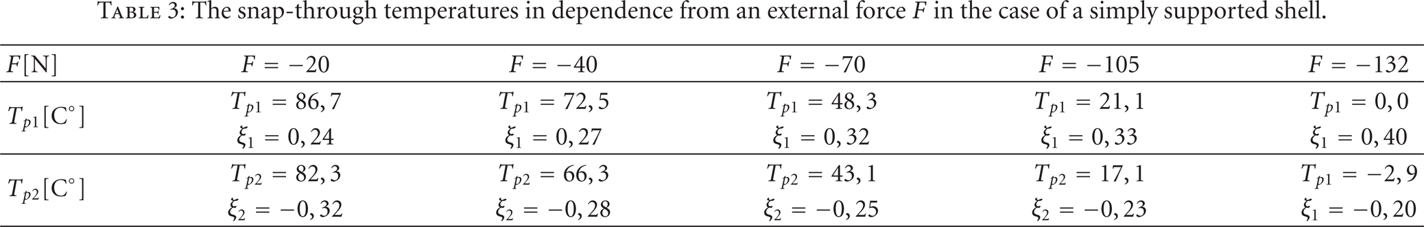
The snap-through temperatures in dependence from an external force at the apex of the shell are written in Table 3, while the shape of the shell at the moment of the upper snap-through with the force F= − 105 N is shown in Figure 14. In Figure 15 the local concavity of the shell due to the concentrated force F at the apex of the shell is evident.
The snap-through temperatures in dependence from an external force F in the case of a simply supported shell.
The geometry of the shell at the start of the upper snap-through in the case of a concentrated force F= − 105 N acting at the apex of the shell.

The occurrence of a local concavity in the case of temperature load and a mechanical force F= − 105 N acting at the apex of the shell.
For the end, we will treat a temperature-loaded shell where all four corners are fixed in such way allowing only rotations at the corners, while the rest of the shell is free to rotate and displace. In other words, a shell fixed so cannot expand horizontally at the corners. Instead of the normal forces N1 and N2 at the boundary conditions (103) we now take into account that the horizontal displacement at the corners of the shell is equal to zero:
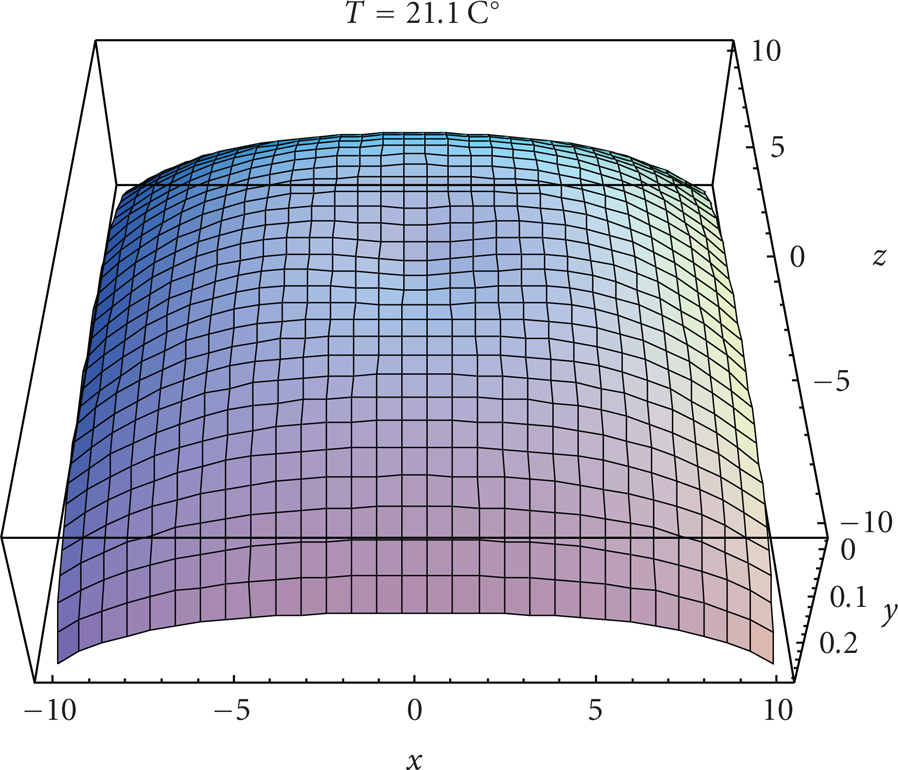
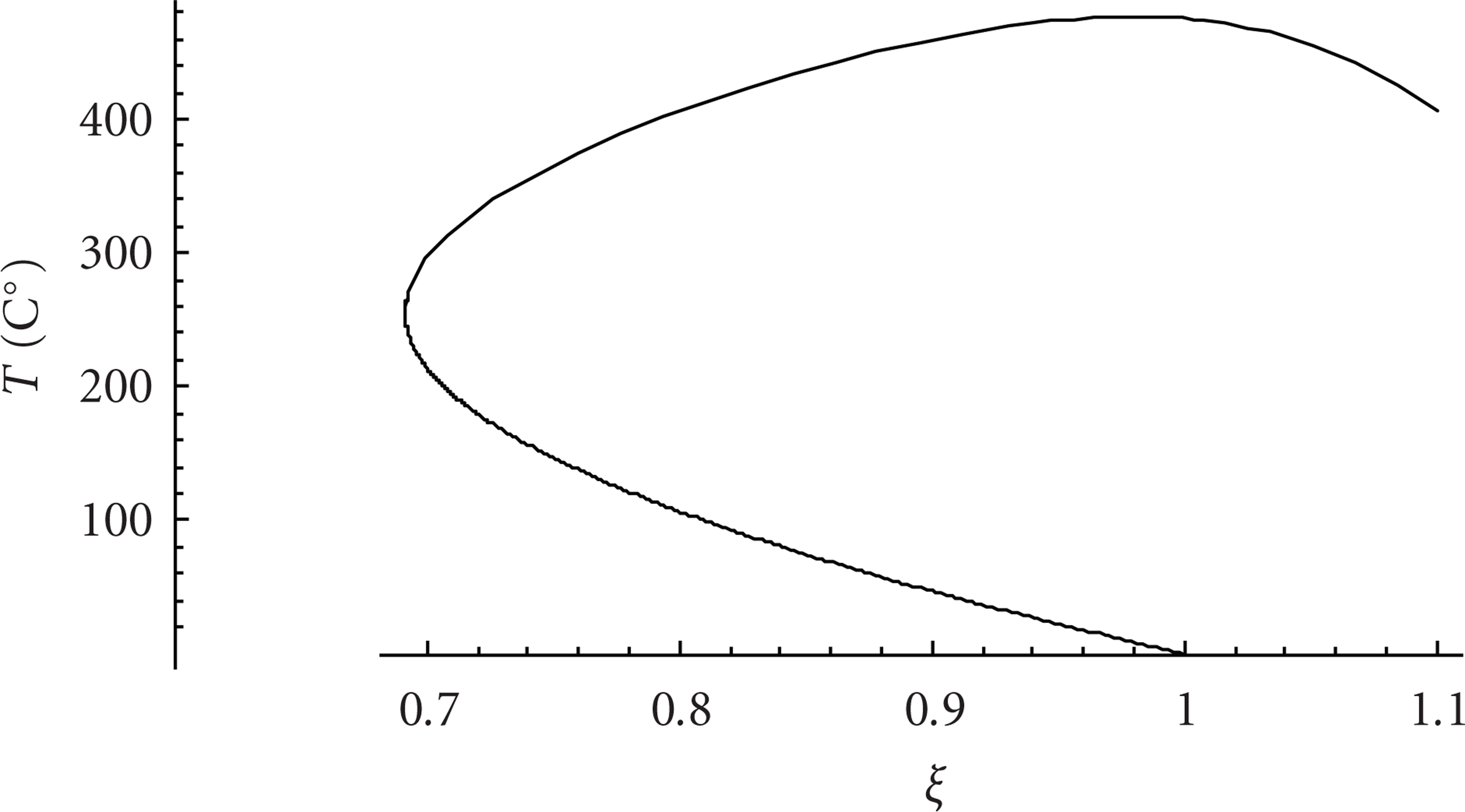
The stability curve that shows the relation of heights ξ in dependence of the temperature T is shown for this example of load in Figure 16. When the shell is heated up to the temperature T=255 C°, the displacements w are positive in the middle of the shell edge and negative at the shell corners. In an overall view, the flatness of the fixed shell is decreased with heating. This fact is evident in Figure 17 which shows the shape of the shell when it is heated to a temperature T=255 C°.
Stability curve for the shell of fixed corners free to rotate.
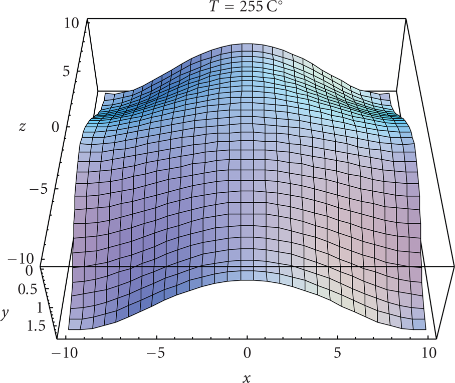
The geometry of a shell at the temperature T=255 C°.
Figure 18 shows the shape of a shell in the unstable equilibrium state when the shell is heated to a temperature T=476 C°. The relation of heights ξ is at that temperature again equal to one. The difference between the initial and deformed geometry of the shell is evident in Figure 19. With reference to the stability curve in Figure 16, which shows that in an unstable region the relation of heights ξ increases, we can conclude that the shell does not snap-through into a convex shape.
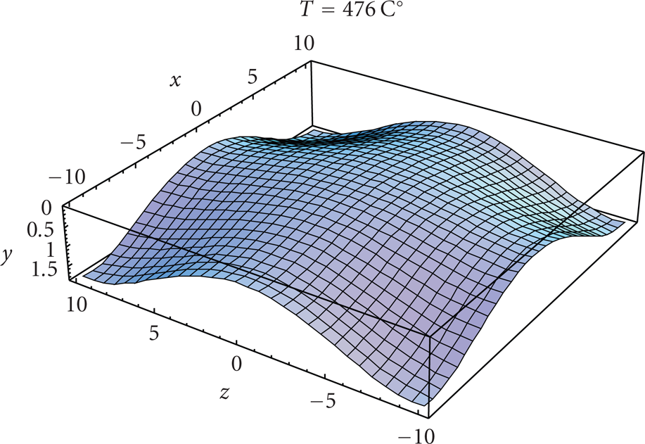
The geometry of the shell at temperature T=476 C°.

A comparison of the initial and deformed shell at temperature T=476 C°.
8. Conclusion
Simply supported thin-walled shallow bimetallic shells have the characteristic to snap-through into a new position at a defined temperature. The snap-through temperature T p is dependent on the material and geometric characteristics of the shell, external mechanical loads, and manner of fixation.
For shallow single layer shells with a constant coefficient of a linear temperature expansion α(z) = const., the relation of heights ξ(T) remains constant regardless to the temperature load. With the increase in temperature T the horizontal radius does somewhat increase, while the vertical component of the displacement w at the shell edge remains the same at all times. This is why single layer shells do not have snap-through. Very shallow bimetallic shells with a small value of the parameter k of construction curves also have no snap-through. We find that a shell with the material and geometric characteristics in (108) has no temperature snap-through if its horizontal radius amounts to a=b≤9,53 mm. The stability curve for the shell in Figure 20 has no local turning points but it has one stationary point at (0,100) which is a horizontal point of inflection. Inflated or less shallow shells snap-through at higher temperatures. With an equal radius a of a bimetallic shell, the temperature of the upper snap-through Tp1 increases with the increase of the parameter k of the construction curves.

Stability curve for a shell with a horizontal radius a=b≤9,53 mm that does not exhibit a snap-through phenomenon.
If an external force F is exerted on the shell, snap-through will occur at a lower temperature comparing to the snap-through temperature Tp1 of an equal shell that is loaded only with a temperature T. At which temperature the shell will snap-through is dependent, not only on the magnitude of the force F and the manner of its distribution on the shell surface but also on the reactions at its boundaries. The snap-through temperature Tp1 is the lowest when the external force F is equalized at all four corners of the shell. With a large enough force F, the shell will snap-through without any additional temperature load.
For snap-through to occur with bimetallic shells it is necessary to ensure, apart from a high enough temperature, that the edges of the shell can freely expand. With a bimetallic free rotating shell that is fixed at the corners, displacements in a horizontal direction are not possible. Such a shell can only expand at the corners in a vertical direction due to which the increase of temperature Talso increases the shell inflatedness. A shell fixed in such a manner cannot perform the function of a thermoswitch.