
Abstract
Successful unfolding in the space is the first step for a satellite antenna to work normally, so that it is important to study the movement reliability of a large deployable satellite antenna. By studying the movement principium, a mechanical analysis model of the deployment mechanism and calculating formulae for the internal forces of trusses were presented. From the performance function of the truss unfolding to meet, a movement reliability analysis model of the mechanism was also given. Synthetically considering the dimension errors and the impact of space environmental factors, we treated the mechanism's movement as a function of random variables and derived the reliability calculation formula by using the method of second-order moment. Finally, the movement probability of the deployment mechanism was simulated by the computer within whole spreading process. The trend of the computing results agrees with the truss model experiments, which shows that the method is reasonable and effective.
1. Introduction
Along with people's exploratory work to the space, a variety of satellite antennas have come out in succession. As a result of the launch vehicle platform size's limit, a large satellite antenna is usually puckered up during the launching stage and will be unfolded under remote control when the satellite has entered into its orbit. Successful unfolding in the space is the first step for a satellite antenna to work normally, and some starting malfunctions of antenna or solar panels have occurred in the aerospace history and led to launch failure. So it is important to study the movement reliability of a large deployable satellite antenna.
The mechanical parts of the deployment equipments on a satellite antenna are usually moveable mechanisms. For changeable structural forms and different failure types, the reliability analysis of a moveable mechanism is usually more complicated and difficult than that of a fixed structure. The movement reliability of a mechanism is calculated mainly by using the perform functions or the security allowances. At present the reliability analysis of a mechanism is not mature in the theory and the method, and the reliability of the mechanism movement function is seldom considered in the previous researches [1–3]. Most research of the deployable satellite antenna focuses on the structural style design and launch dynamics analysis [4–9]. The deployment mechanism design of a large meshed space antenna was introduced in [4], and the analysis of its principle of work was also presented. The kinetic characteristic of deployment mechanisms and the vibratory characteristic of an antenna were investigated in [5]. The work in [6] discussed the role of environmental testing to enhance the reliability of spacecraft as well as the relationship between environmental test and reliability test. In [8], two concepts of deployable truss structures were compared in view of the required deployment force against the mesh surface tension. The comparison was performed using the flexible multibody dynamics computer code that the author developed. The work is [9] gave the kinetic analysis of deployable scissor structures.
We investigated the blue print of a large truss-board satellite antenna and tentatively forecasted the antenna unfolding probability, with emphasis on the analysis and prediction of the mechanism reliability by using movement function.
2. Principium of the Hoop-Truss Deployment
This paper deals with a large deployable satellite antenna with hooptruss. The antenna has a paraboloidal mesh reflector, the long-axis diameter of which is about 17 m. The reflecting surface of it consists of a metallic web and some tensed cords. It is unfolded by using a hoop-truss deployment mechanism. Figure 1 shows the axonometric drawing of the antenna.
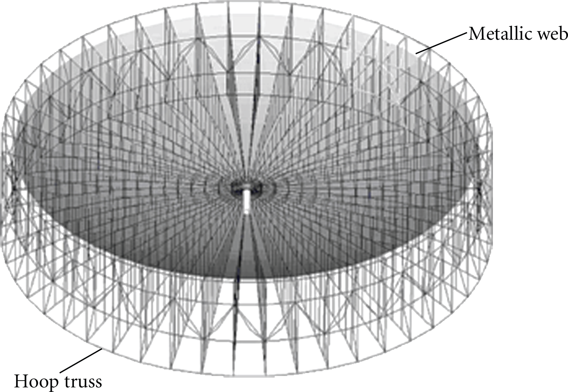
Axonometric drawing of the antenna.
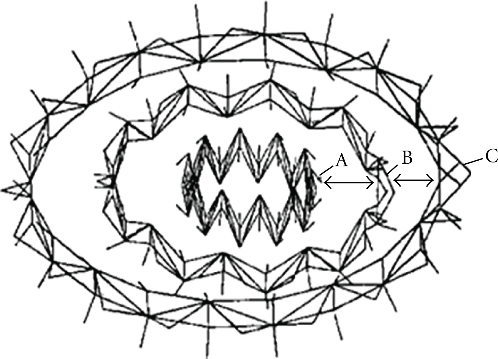
The hooptruss has 48 structural units, and each of which has a rectangular framework and a shrinkable bar along one diagonal line of the rectangular. Some expandable outriggers are fitted at the endpoints of the rectangular to improve the structural stiffness. The truss bars are connected to each other by node joints and tight cords. A sketch map of two units of the hooptruss is given in Figure 2. It shows the structural composition and connection of hoop trusses, where 1,3,5 are four-bar nodes, 2,4,6 are eight-bar nodes, 7 is a two-bar node, 8 ≾ 17 are truss bars, and 18 ≾ 29 are tight cords.

Two units of the hooptruss.
The whole unfolding process of a satellite antenna involves three stages: unlocking, expansion, and orientation.
At the first stage, the binding cordages around the antenna structure desquamate to make the antenna in a nonrestraint condition. Under the force of torque spring, each joint truss opens to a slight angle.
At the second stage, the fixed electromotor starts driving a wheel to enwind a hauling rope around it. The shrinkable bar along one diagonal line of the structural unit is made hollow for the hauling rope to pass through. As the hauling rope enwinds around the rolling wheel, the length of the shrinkable bar shortens and the shape of each truss unit changes from a slender rhombus to a rectangle.
At the last or orientation stage, the electromotor shuts down when the length of each shrinkable bar has shortened to the minimum. Under the forces of knuckle blocks and tight cords, the antenna structure expands to the maximum extent and maintains lock status.
The principium of the deployment mechanism is shown in Figure 3, and a schematic drawing of the deployment process is given in Figure 4.

Principium of the deployment mechanism.
Schematic drawing of the deployment process.
3. Mechanical Analysis of the Hoop-Truss Deployment
The mechanical analysis chart of two hoop-truss units is shown in Figure 5, where T is the tension force of the hauling rope. The deployment of a large antenna structure is so slowly that it will take about an hour to spread out. Thus the antenna is approximately in a static equilibrium at each moment of the deployment. Being in weightlessness of the space environment, the deadweight of the whole antenna structure can be ignored. At the expansion stage, the cords between truss bars are in looseness, and so the tension forces of cords are also neglected.

Configuration of two truss units.
3.1. Spatial Position of Truss Bars
From the triangle relationship shown in Figure 5 we find that
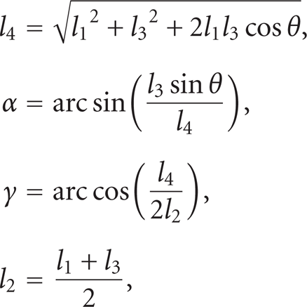
in which l i (i=1,…,4) means the length of L i bar, α is the included angle between bars of L1 and L4, γ is the angle between L2 and L4, and θ denotes the angle between L1 and L3.
We view β as the projected angle of L3 bar of two units on the X-O-Z coordinate plane. The projection of circumferential bars of 48 units on it is a regular polygon, so that

3.2. Internal Force of Each Bar
From Figure 5, according to symmetry, the equations of force projection are given as follows.
At node B, along the y-axis,
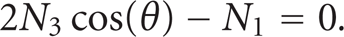
At node A, along the y-axis,

and along the Z-axis,

Solving the simultaneous equations from (3) to (5), we can get the internal force of each bar:

where N i (i=1,2,3) is the internal force of L i bar. We suppose that each bar is under pressure, which is defined as a positive internal force. It has been proved that the composite force along Z-axis is not equal to zero at nodes B and D. It is just the composite driving force for the hoop-truss to spread.
4. Probability Analysis of the Hoop-Truss Deployment
4.1. Building the Probabilistic Model
In the deployment mechanism, a trussbar is connected to others by some knuckles, and the unfolding power comes from an electromotor. The resistances are calculated in moments, which come from frictional resistances caused by knuckles and high-frequency cables and from thermal deformation of the antenna structure. The frictional moment of resistances in knuckles is calculated by the normal pressure on shaft axles multiplied by the friction coefficient between the knuckle materials. The total resistance moment can be estimated approximately as one that is k M times larger than the frictional moment, where k M is a synthetic influence coefficient.
If the hooptruss can be unfolded successfully, one of the following performance functions should be satisfied.
The driving moment is always larger than the resistance moment during deployment.
Such a performance function of movement is corresponding to a limiting state that

where Z M (θ) is a performance function expressed in moments, M a (θ) is the total driving moment, and M r (θ) is the total resistance moment. θ0 and θ m are, respectively, the start- and end-angle of deployment; Z M (θ), M a (θ), and M r (θ) are functions varying with the unfolding angle θ.
Let the radius of a knuckle shaft be R, and let the friction coefficient between the shaft and muff be f. Considering the effect of dimensional errors, assembling errors and random factors in the space environment, we can treat actual values of the towing force T, the radius R, and the friction coefficient f as random variables. So the movement function Z M (θ) is a function of random variables T, R, and f.
By using the second-moment method in probability theory [10], the fiduciary level β M and the movement probability P r M of Z M (θ) can be deduced:
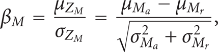

where μ( * ) is the mean value of a random variable ( * ), σ( * ) is the mean square deviation of it, and Φ( * ) is the standard normal distribution function.
The driving moment does more work than the resistance moment during deployment.
After deployment starting, if the accumulative work done by the driving moment is larger than that done by the resistance moment, the unfolding process will continue. The equations of limiting state, the fiduciary level, and the movement probability of such a performance function are, respectively, given as follows:


where Z W (θ) is a performance function expressed in works, W a (θ) is the accumulative work done by the driving moment, and W r (θ) is that by the resistance moment. Z W (θ), W a (θ), and W r (θ) are functions varying with the unfolding angle θ, and they are also functions of random variables T, r, and f.
If either of the above two performance functions can be satisfied, the hooptruss will be able to deploy.
4.2. Derivation of Reliability Formulae
4.2.1. Calculating the Movement Probability in Moment Form
When the hooptruss unfolds, the maximum of the total resistance moment is (refer to Figure 5)
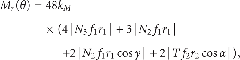
where f1 is the friction coefficient in truss knuckles and f2 is that in pulley wheels; r1 and r2 are, respectively, the shaft radius in truss knuckles and in pulley wheels. The driving moment is offered by the towing rope:

Substituting (13) and (14) into (7), we arrange the limiting condition function as

where A(θ),B(θ), and C(θ) are deterministic functions about the bar-length l i and the unfolding angle θ. By using the second-moment method [10] of a random function, the mean value and the square deviation of Z M can be given as follows:

Substituting the right parts of the above two equations into (8) and (9), the fiduciary level β M and the movement probability P r M can be calculated, respectively.
4.2.2. Calculating the Movement Probability in Work Form
If the included angle θ has a little change of dθ, the differential of the work done by resistance moments (refer to Figure 5) is

and the differential of the work done by the driving moment (refer to Figure 2) is

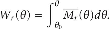
When the truss structure has unfolded from angle θ0 to θ, the total accumulative work done by resistance moments is
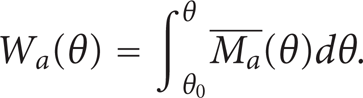
On the other hand, the total accumulative work done by the driving moment is
The limiting condition function Z W (θ) is arranged as

In the previous formulae, r3 is the radius of pulley wheels in the deployment mechanism, which is a determinant parameter; E(θ),F(θ), and G(θ) are determinant functions about bar-length l i and unfolding angle θ.
The mean value and the square deviation of Z W are given, respectively:

Substituting the right parts of the above two equations into (11) and (12), the fiduciary level β W and the movement probability P r W can be calculated.
5. Calculating the Deployment Probability of Hoop-Truss
The data of the deployment mechanism are given as follows.
The lengths of trussbar are l1 = 1400 mm, l3 = 1050 mm; the diameter of knuckle shaft is D1 = Φ12− 0.10 mm, and that of pulley shaft is D2 = Φ16− 0.10 mm; the diameter of the pulley wheel is D3 = Φ30 mm; the mean value of the friction coefficient at the truss nodes is μ
f
1
= 0.15, and at the pulley wheels is μ
f
2
= 0.2, which has the same coefficient of variation v
f
1
= v
f
2
= 0.1; the mean value of tension force in the towing rope is μ
T
= 150 N, which has the coefficient of variation v
T
= 0.1; the variation range of the unfolding angle θ is
Based on the method of this paper, with the synthetic influence coefficient k
M
= 2.5, the bounds of truss-bar internal forces are N1∊
From curves shown in Figure 6 we can see that the mean value of the total damping moment M
r
∊

Curves of moments and the fiduciary level.
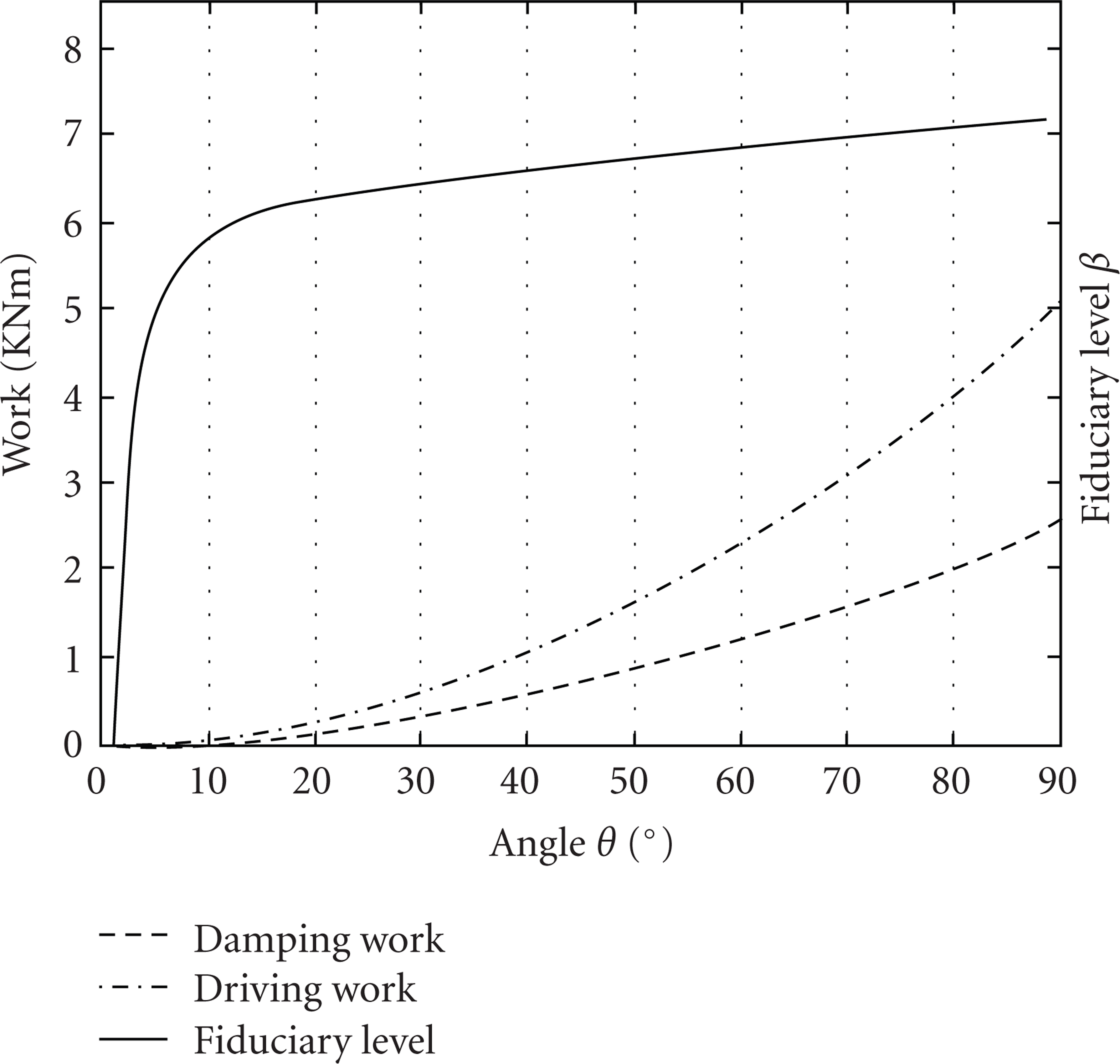
From curves shown in Figure 7, the mean value of the work done by the driving moment is W
a
Curves of works and the fiduciary level.
If calculated in moment form, the movement probability of the deployment mechanism is P r M ≥Φ(2.683) = 0.996351; if calculated in work form, the movement probability of the deployment mechanism is P r W ≥Φ(0) = 0.5. It is ought to consider both the two factors; therefore we use a logic model [10] of parallelconnection to get the deployment probability P r = 1 − (1 − P r M )(1 − P r W )≥0.998176.
6. Conclusion
(1) Models of mechanical analysis and movement probability of the hooptruss are presented in this paper, which provides some theoretic methods for the study on the deployment mechanism of a large satellite antenna.
(2) The movement reliability of the deployment mechanism during the whole spreading is predicted. The trend of the computing results agrees with model experiment process, which shows that the method of this paper is reasonable and efficient.
Footnotes
Nomenclature
Acknowledgment
This research work has been sponsored by the National High-tech Research and Development Program (863 Program), funded project (2006AA04Z402), China.