
Abstract
The local, nonuniform heating and subsequent cooling during the welding processes causes complex thermal stress/strain fields to develop that finally leads to residual stresses, distortions, and their adverse consequences. Residual stresses are of prime concern to the industries producing weld-integrated structures around the globe because of their obvious potential to cause dimensional instability in welded structures, contribute to premature fracture/failure, along with the significant reduction in fatigue strength and in-service performance of the welded structures. Arc welding with single or multiple weld runs is an appropriate and cost effective joining method to produce high-strength structures in these industries. A multifield interaction in arc welding process makes it a complex manufacturing process. A number of geometric and process parameters are contributing to significant stress levels in arc-welded structures. In the present analysis, parametric studies are conducted for the effects of a critical geometric parameter, that is, tack weld on the corresponding residual stress fields in circumferentially welded thin-walled cylinders. Tack welds offer a considerable resistance to the shrinkage and the orientation, and size of tacks can alter altogether the stress patterns within the weldments. Hence, a critical analysis for the effects of tack weld orientation is desirable.
1. Introduction
Circumferentiallyarc welded thin-walled cylinders have a key role in nuclear, aerospace, marine engineering, and pressure vessels applications. Gas tungsten arc welding (GTAW) is a common joining technique employed for high strength welding of these structures. Residual stress fields as consequences of nonlinear thermal gradients during welding are unavoidable. Actually intense localised heating (expansion) followed by rapid cooling (contraction) of the material in and around the weld region produces significant residual stress fields [1]. This high magnitude residual stresses of the order of yield strength of the material [2] within the heat-affected zone (HAZ) can be a major threat for the in-service structural integrity of welded structures.
Precise prediction of residual stress fields (magnitude and trends) is not an easy task due to complexity involved including short-term localised heating and rapid cooling, temperature-dependent material behaviour, moving heat source, and metallurgical transformations. Accordingly, FE-based numerical simulations gained a considerable popularity in predicting the adverse consequences of welding phenomenon in the last three decades [3–5]. A significant contribution for the analysis of residual stress fields in circumferentially welded structures focusing on pipe and cylinders is available in literature [6–13]. As the computer simulation of welding processes is highly computationally intensive and a large computer storage and CPU time are required, most of the previous research reduces computational power requirements by simplifying assumptions such as rotational symmetry and lateral symmetry in numerical simulations [7–10]. These assumptions reduce the computational demand at the cost of results’ accuracy because the model was over simplified by limiting the solution domain to only a section of the whole domain with forced symmetry assumptions which did not prevail.
Further, these simplified assumptions do not have the capability to capture the considerable effects of weld start/stop and weld tack modelling. In this regard, an experimental work by Jonsson and Josefson [14] and some three-dimensional finite element (FE) studies [12, 13, 15] reported deviations from rotational symmetry, especially at the beginning and end of the welding cycle for circumferential joint in welding of pipes with lateral symmetry. Dong and Burst [16] and Dong [17] in their research demonstrated that both the moving heat source and weld start/stop effects are inclined to violate the axis-symmetric conditions. The circumferential variation in residual stresses was presented by the authors to strengthen the statement. Later by using a full three-dimensional model for multipass welding of pipes, Fricke et al. [18] conclude that residual stresses are by no means axis-symmetric. Although a number of three-dimensional FE-based numerical investigations are available in published literature for circumferential welding of pipes/cylinders, some detailed three-dimensional FE models to get insight of this complex phenomenon are still lacking and need to be explored. Further, no significant contribution, pertaining to the numerical modelling of the effects of tack welds orientation for circumferentially welded geometries, appears in the literature before the studies conducted by Abid and Siddique [19]. However, the issues of tack welds in butt-welded plates were previously discussed by [20–22]. Jonsson et al. presented the effects of tack weld sequence in welded plates by assuming plane stress problem for simplification [20, 23]. In another study, Murakawa [21, 22] used temperature-dependent interface elements for modelling root gap and tack welds. These studies conclude that tack welds and root gap have significant effects on structure axial deformations. In 2005, Allen [24] presented a first detailed study on FEM modelling and the structural consequences of root gap and tack welds in circumferentially, butt-welded pipe flange joints. In the present research, the parametric studies based on the effects of tack weld modelling are presented. The tack weld models are developed based on the guidelines presented by Abid and Siddique [19]. To the best of author's knowledge, the present studies may be considered as the first effort in this regard for circumferentially, butt-welded thin-walled cylinders.
2. Present Study
In the present analysis, three-dimensional FE models are employed and parametric studies are conducted for the effects of tack welds on the corresponding residual stress fields. Normally tack welds are used to restrain the excessive axial shrinkage and maintain the desired root opening. To be effective, thought should be given to the number of tack welds, their length, and the distance between them [24]. Tack weld offers a considerable resistance to the shrinkage and the orientation, and size of tacks can alter altogether the stress patterns within the weldments. Hence, a critical analysis for the effects of tack weld orientation with reference to the weld start position is desirable. Two tack welds, circumferentially opposite to each other, with same length in circumferential direction along the weld path are modeled for all the case studies. Although the model is similar for all the parametric studies, however for the variation of tack weld orientation, position of live elements representing tack welds in all the studies is different. The details of the parametric studies are summarised in Table 1.
Different tack weld orientations studied.

The temperature-dependent thermophysical properties such as conductivity, specific heat and density, and temperature-dependent thermal-structural properties including Young's modulus, Poisson's ratio, thermal expansion coefficient, and yield strength are used for thermal analysis and mechanical analysis, respectively. The metallurgical and mechanical consequences of phase transformation have been considered in numerical modelling of welding process. The properties for low carbon steel taken from [25] and shown in Figure 1 are used in the analysis. The analysis is performed by using ANSYS, a commercial finite element code enhanced with author written subroutines. Same material properties except yield stress are utilised both for base and weld metals. Comparatively higher yield stress as depicted inFigure 1(b) is used in the analysis. Thermal conductivity for molten metal is artificially increased to 120 Wm-1°C-1 to simulate the enhanced convective heat transfer effects (stirring effects) due to molten fluid flow (refer to Figure 1(a)).
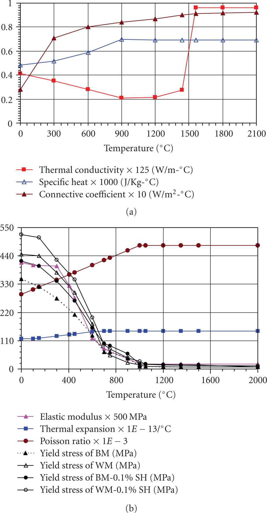
(a) Thermophysical, (b) thermomechanical properties of low carbon steel as a function of temperature used in the present study [25].
3. Recipe for Welding Simulation
Evolution of highly nonlinear, transient, thermal and consequently the residual stress fields is a fairly complex phenomenon associated with arc welding process. Short term localised but intense heating results in molten weld pool. The weld pool shape can be largely influenced by the weld metal transfer mode and corresponding fluid flow dynamics [26]. Therefore, in order to capture the multifield interaction, a successful recipe for FE-based numerical simulation strategy at least caters for the interaction between the thermal, metallurgical, and structural transformations.
Welding process is a coupled thermomechanical phenomenon. Structural fields are strongly dependent on the thermal fields whereas, structural fields have weak influence on thermal fields [5–7]. Hence, inherently coupled phenomenon of welding can be safely split into two sequentially coupled thermal followed by structural analysis. Further details pertaining to FE simulation in the present research are discussed in following sections.
3.1. FE Model
Full three-dimensional FE model for the circumferential welding of two cylinders with “V” groove developed in ANSYS is shown in Figure 2. The element type in thermal analysis is SOLID70 (linear 8-node brick element with one degree of freedom, i.e., temperature at each node). In structural analysis, SOLID45 (linear 8-node brick element with three degrees of freedom at each node, i.e., translations in the nodal X, Y, and Z directions) is used. Due to anticipated high temperature and flux gradients in and around the fusion zone (FZ) and heat-affected zone (HAZ), a relatively fine mesh is used within a distance of 8 mm on both sides of weld line (WL). Two tack welds at different locations, circumferentially opposite to each other for different case studies as referred in Table 1, are modeled, each 7.7 mm in circumferential direction. FE model includes total 42560 elements and 51800 nodes. The minimum element size, of course, in the FZ is 1 mm × 1.1 mm × 0.75 mm.
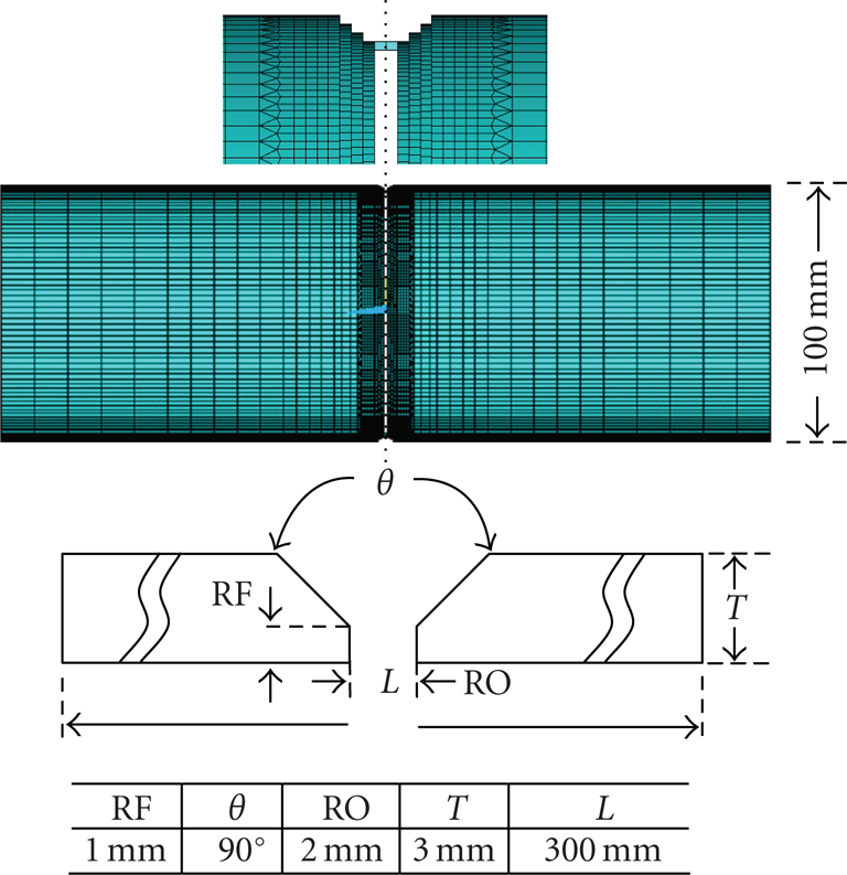
Three-dimensional FE model with geometry detail.
3.2. Heat Source Modelling
In the present analysis, to represent the heat generated by the torch in GTAW, a heat source model was developed and implemented by author written subroutines. For the heat input distribution to the weldments, the most widely acceptable double ellipsoidal heat source model, presented by Goldak et al. [27] as shown in Figure 3 is used to present the heat generated by the welding torch. The variations due to curvature of the cylinders are not taken into account. The model gives the Gaussian distribution for circumferential welding and has excellent features of power and density distribution control in the weld pool and HAZ. The spatial heat distribution in a moving frame of reference can be calculated with the governing equations (1) [27], where Q=VI,f f +f r = 2. Q is the total heat input (watts), V is the welding voltage (volts), and I is the welding current (amperes)

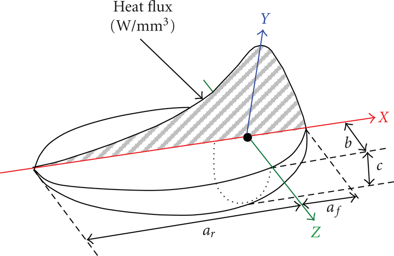
Heat source model [27].
To simulate the welding torch movement with the specific welding speed, the calculated volumetric heat flux densities are required to be assigned to specific elements around the welding areas in the FE model. By keeping the origin of the coordinate system located at the centre of the moving arc, an author written APDL subroutine is used to calculate the centroidal distance of elements from the moving arc centre corresponding to the arc position at any instant.
Based on the FE mesh generated by the ANSYS, definitions of the welding process parameters and characteristics of the heat source transient heat fluxes representing the moving distributed heat source can be calculated on specific positions in welding areas.
The heat source is assumed to move through volume and calculated heat is applied to elements as volumetric heat generation so that the elements lying on the surface can be used for modelling of surface heat convection which otherwise requires laying of additional two dimensional surface elements for convection modelling.
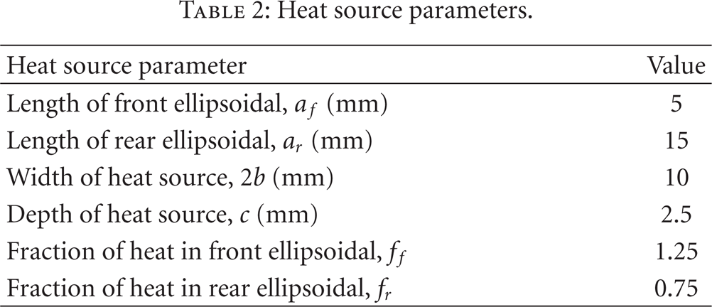
The numerical values for heat source parameters used in this paper are shown in Table 2. Welding process parameters, calibrated through the experimental investigations presented in Section 5, are shown in Table 3.
Heat source parameters.
Welding process parameters.

3.3. Filler Metal Deposition
Conventional quiet element technique [28], which is relatively straightforward and easy to implement by utilizing the ANSYS embed features of element birth and death, is used in the present work. The whole FE model is generated in the start; however, all elements representing filler metal are deactivated by assigning them very low conductivity. During the thermal analysis, all the nodes of deactivated elements (except those shared with the base metal) are also fixed at ambient temperature till the birth of the respective element. Deactivated elements are reactivated sequentially when they come under the influence of the heat source (welding torch).
3.4. Thermal Simulation Strategy
For the determination of realistic temperature profile, a very careful and accurate thermal analysis with appropriate boundary conditions such as heat transfer by conduction, heat losses due to convection and radiation, and heat input from the welding torch along with the effects of filler metal deposition is of paramount importance. During the welding, the governing equation for transient heat transfer analysis is given by (2)

where ρ is the density of the material, c is the specific heat capacity, T is the current temperature, q is the vector of heat flux, Q is the rate of internal heat generation, t is the time, ∇ is the spatial gradient operator, and x, y, z are the coordinates in the reference plane. The nonlinear isotropic Fourier heat flux constitutive equation, that is, (3) is employed

where k is the temperature-dependent thermal conductivity.
Combined heat transfer coefficient for convection and radiation as used by [28, 29] is calculated and applied on all the applicable surfaces. The heat losses from the surfaces are modelled from (4)

where A is the surface area, T is current temperature, Tamb is the ambient temperature, and htotal is combined convection and radiation coefficient, given by (5)

where h isthe thermal convection coefficient. In the present analysis, temperature-dependent value for h is used as shown in Figure 1(a). ε is the radiation emmissivity, σ is Stefan Boltzmann constant (5.67×10⁻⁸ Wm-1 K-4) on the surface of the steel under investigation in the present study, ε=0.51 is used which is the average value for hot-rolled steel plates. Tamb is taken as 300 K equal to the room temperature. The heating time along the weld path is about 105 seconds with a torch speed of 3 mm s-1, and the complete welding sequence is divided into 280 incremental equally spaced load/solution steps of 0.37 second. Stepped load option available in ANSYS is used for effective application of thermal load during the load step. After extinguishing the arc, additional 60 load steps of different lengths are used for cooling of the weldment. The total cooling time to return to the ambient temperature of 300 K is about 22.6 minutes (1356 seconds) from the start of the cooling phase.
3.5. Structural Simulation Strategy
In the sequel mechanical analysis, the temperature history of each node from the preceding thermal analysis is input as nodal body load in conjunction with temperature-dependent mechanical properties and structural boundary conditions. Thermo-elastic-plastic material formulation as shown in (6) [30] with von mises yield criteria is employed with σ1, σ2, and σ3 being the three principal stresses, coupled to a kinematic hardening rule,

Same meshing parameters from thermal analysis to facilitate the nodal data mapping and elements with same topology to enhance the convergence during the structural analysis are used. The critical issue of element birth and death from the thermal analysis is handled by an author written subroutine. A sequential birth of an element takes place when the element reaches the solidification temperature. Melting and ambient temperatures are set as the temperatures at which thermal strains are zero for thermal expansion coefficients of the filler and base metals. Additionally, to handle the excessive distortion issues, initial strains in the elements are set to zero at the time of element reactivation. In structural analysis, the only boundary condition is the constraints applied to represent the clamping of the cylinders to be welded in welding positioners. During analysis (both thermal and structural), a “full Newton-Raphson” iterative solution technique with a direct sparse matrix solver is used for obtaining the solution. During the thermal cycle, temperature, and consequently temperature-dependent material properties, changes very rapidly; thus, a full Newton-Raphson scheme, which uses a modified material properties table and reformulated stiffness matrix at every equilibrium iteration, is believed to give more accurate results than other options such as modified or initial Newton–Raphson schemes. Line search option of the FE code ANSYS is set to ON to improve convergence. A single point reduced integration scheme with hourglass control is implemented to facilitate convergence and to avoid excessive locking during structural analysis.
4. Experimental Validation
To ensure the reliability of the FE models, GTAW experiments on two thin-walled cylinders with similar geometric and welding process parameters from Figure 2 (tack welds at 0°–180°) andTable 3 are conducted. Low carbon steel equivalent to AH36 with chemical composition as shown by [31] is utilized. In addition to the FE parameters, argon with 99.999% purity was used as shielding gas with 15 litres/min flow rate. High-tech fully automatic SAF GTAW welding equipment along with rotary positioners and welding fixtures was used to reflect the desired structural boundary conditions.
For thermal model validation, K-type thermocouples at four different locations were placed and temperature is recorded through the data logger after every 10 seconds of time interval for comparison with FE results. A quantitative comparison of measured and predicted transient temperatures at thermocouple locations is presented in Figure 4. The thermocouple results show close agreement with the FE data.

Comparison of predicted and measured temperature profiles at different locations on cylinder outer surface.
For structural model validation, residual stresses are measured at some specified points for comparison through the predicted results. A centre hole drilling strain gauge method [32] is used to measure the residual hoop and axial stresses at specified locations, that is, points P1 to P3 on the cylinder outer surface and P4 to P6 on the cylinder inner surface as depicted in Figure 5. A quantitative comparison of residual stresses from experiments with FE predicted can be found in Figure 8. The qualitative comparison of nodal temperatures and residual stresses from Figures 4 and 5 showes that predicted results agreed well with the experimental data. Thus the developed models have been experimentally validated.

Comparison of predicted and measured residual stresses at cylinder inner and outer surfaces.
5. Results and Discussion
Axial residual stresses for different tack weld orientations at a longitudinal section 180° from weld start position for outer and inner surfaces are shown in Figures 6 and 7, respectively. Important considerations are as follows.
Axial residual stress variations at a longitudinal section 180° from weld line on cylinder inner surface for different tack weld orientations.

Axial residual stress variations at a longitudinal section 180° from weld line on cylinder outer surface for different tack weld orientations.

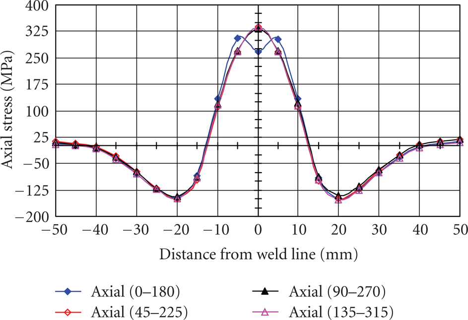
Axial residual stress variations at a circumferential path on weld line for cylinder outer surface.
On inner surface, for all tack weld orientations, the axial residual stress fields are identical in trend and magnitude. Some exceptions are, however, observed for tack weld orientations of 0°–180°. In this case, due to tack weld at weld start position of 0°, lower residual axial stresses are shown. The tack acts as a stress reducer, and a gain in stress reduction of about 70 MPa at weld line is observed. On the other hand, a slightly larger stress zone of influence is also observed for this case.
On outer surface in Figure 7, again similar (both in trend and magnitude), compressive residual stress fields are shown. A significant stress enhancement (about −120 MPa) at weld line for tack welds at 0°–180° is observed.
Variation in axial residual stress fields for different tack weld orientations, at a path on the weld line along the circumference for outer and inner surface of the cylinder, is presented in Figures 8 and 9, respectively. Generally, axial residual stresses are compressive on outer surface and tensile on inner surface. The following are the important observations.

Axial residual stress variations at a circumferential path on weld line for cylinder inner surface.
The axial residual stress fields are identical in trend and magnitude on both outer and inner surfaces, with some exceptions at tack weld orientations.
For all the four cases, the effects of weld start/end are obvious on stress variations showing strong influence of weld start/end on axial residual stresses. On outer surface, the effects of both weld start and end are significant. However, on inner surface, the effect is more pronounced at the weld start only.
On outer surface, a considerable compressive axial residual stress enhancement at the tack weld locations is shown. Maximum compressive axial residual stress of about 400 MPa at tack weld locations of 90°, 180°, and 270° is observed. Also at tack, weld locations of 135° and 315°, residual compressive stresses of 350 MPa are observed.
On inner surface, a slight beneficial effect of tensile axial residual stress reduction effect at the tack weld locations is shown. Maximum tensile axial residual stress reduction of about 55 MPa at tack weld locations of 90°, 180°, and 270° is observed. No significant tensile stress reduction is shown at tack weld locations of 135° and 315°.
To understand the mechanism of stress enhancement/reduction for tack welds at weld start location for outer/inner surfaces, respectively, transient axial stress fields on two points at 135° and 180° from weld start (0°) on cylinder inner surface are investigated. For this, nodes at 135° on the weld bead and 180° on the centre of the tack weld from the weld start on inner surface are selected from the FE mesh and transient axial stresses are shown in Figure 10. During thermo-mechanical analysis, the node at 135° from the weld start position belongings to the weld bead elements remains stress-free (deactivated) during the heating phase. Further, it remains deactivated during the cooling phase and gets activated (stresses start to build up) as it reaches a solidus temperature of 1713 K.

Transient axial stresses at two selected nodes 130° and 180° from weld start position on cylinder inner surface and at the weld line for tack weld orientation of 0°–180°.
Referring to temperature-dependent yield strength of AH36 low carbon steel, previously presented in Figure 1, due to very low yield-strength at elevated temperature (>750°C) the stress accumulation is not significant (┼100 MPa). Figure 11 presents the transient axial stresses as a function of temperature for two same nodes as discussed above. An axial stress of about 100 MPa is observed at a temperature of about 695 K. Below 600 K, the axial stress increases significantly due to considerable increase in yield strength value.
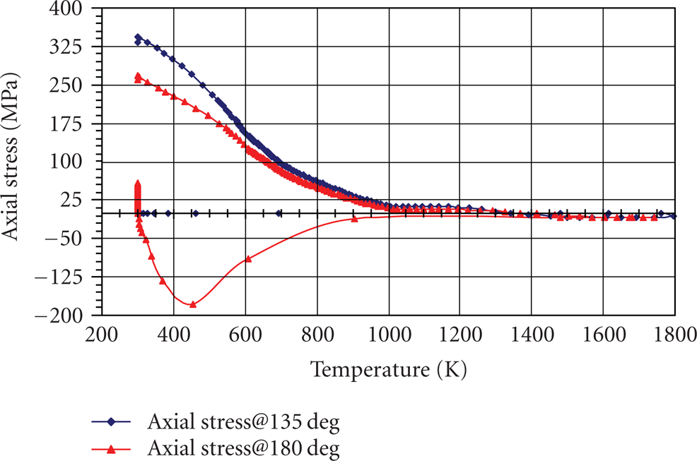
Transient axial stresses at two selected nodes 130° and 180° from weld start position on cylinder inner surface and at the weld line as a function of temperature for tack weld orientation of 0°–180°.
The node at 180° belongs to the tack elements at 180° which remains activated throughout the heating and cooling phases. As the heat source (welding torch) starts moving around the cylinder periphery (or rotary positioner starts rotating with stationary torch as in case of experiments conducted in present research), the already laid cooling weld bead behind the torch starts to accumulate stresses on the tack welds. From Figure 11, it is obvious that the transient axial stress is tensile (≾58 MPa maximum) initially before the torch reaches the tack weld at 180°. A little before the torch reaches the tack weld, the stress reversal from tensile to compressive is shown and a compressive stress of about 47 MPa is obtained before the torch positioned at tack weld. On heating, this compressive stress enhances to a maximum of about 178 MPa and again starts decreasing (approaching towards tensile). Again, a stress reversal from compressive to tensile after 60 seconds is shown.
Compressive axial stress is observed at a temperature less than about 1000 K from Figure 11. Above 1000 K, the axial stress approaches almost zero during the entire heating phase. Further, cooling to less than 1000 K, a considerable tensile axial stress is shown due to increasing yield strength at low temperature. The differential temperature distribution on the tack weld produces positive thermal strains, when restrained by the surrounding material causes elastic strains and then dominating negative plastic strains as depicted in Figures 12 and 13, respectively.
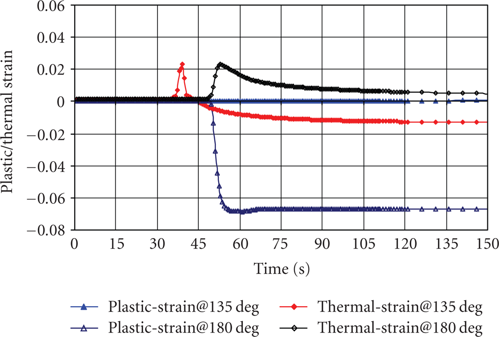
Transient plastic/thermal strains at two selected nodes 130° and 180° from weld start position on cylinder inner surface and at the weld line as a function of temperature for tack weld orientation of 0°–180°.

Transient elastic strains at two selected nodes 130° and 180° from weld start position on cylinder inner surface and at the weld line as a function of temperature for tack weld orientation of 0°–180°.
6. Significant Conclusions
Computationalmethodologies based on FE simulation are presented and parametric studies are conducted to analyse the effects of varying tack weld orientations on residual stress fields (magnitude and trend). From the results presented, it is concluded that identical axial residual stress fields are observed on cylinders outer and inner surfaces for all the tack weld orientations under study with some exceptions on tack welds and weld start/stop locations. On the outer surface, the effects of both start and end are pronounced whereas, on inner surface only the effects of weld start are pronounced.
Footnotes
Acknowledgments
The authors are highly indebted to the National University of Sciences and Technology (NUST) and Higher Education Commission (HEC) of Pakistan for the support provided for the research work.