
Abstract
A great variety of natural and synthetic polymer materials have been utilized in soft tissue engineering as extracellular matrix (ECM) materials. Natural polymers, such as collagen and fibrin hydrogels, have experienced especially broad adoption due to the high density of cell adhesion sites compared to their synthetic counterparts, ready availability, and ease of use. However, these and other hydrogels lack the structural and mechanical anisotropy that define the ECM in many tissues, such as skeletal and cardiac muscle, tendon, and cartilage. Herein, we present a facile, low-cost, and automated method of preparing collagen microfibers, organizing these fibers into precisely controlled mesh designs, and embedding these meshes in a bulk hydrogel, creating a composite biomaterial suitable for a wide variety of tissue engineering and regenerative medicine applications. With the assistance of custom software tools described herein, mesh patterns are designed by a digital graphical user interface and translated into protocols that are executed by a custom mesh collection and organization device. We demonstrate a high degree of precision and reproducibility in both fiber and mesh fabrication, evaluate single fiber mechanical properties, and provide evidence of collagen self-assembly in the microfibers under standard cell culture conditions. This work offers a powerful, flexible platform for the study of tissue engineering and cell material interactions, as well as the development of therapeutic biomaterials in the form of custom collagen microfiber patterns that will be accessible to all through the methods and techniques described here.
Impact Statement
Collagen microfiber meshes have immediate and broad applications in tissue engineering research and show high potential for later use in clinical therapeutics due to their compositional similarities to native extracellular matrix and tunable structural and mechanical characteristics. Physical and biological characterizations of these meshes demonstrate physiologically relevant mechanical properties, native-like collagen structure, and cytocompatibility. The methods presented herein not only describe a process through which custom collagen microfiber meshes can be fabricated but also provide the reader with detailed device plans and software tools to produce their own bespoke meshes through a precise, consistent, and automated process.
Introduction
An expansive variety of natural and synthetic polymer hydrogel materials has been used in soft tissue engineering because of their versatility, permitting a high degree of customization for individual applications (reviewed in Jafari et al. 1 ). Tissue engineers are able to select from a vast library of hydrogel scaffolds (defined by molecular composition and organization) and choose a composition best suited to the cell and tissue type of interest in terms of cell adhesion site availability and density, mechanical stiffness and strength, remodeling/degradation rate and cleavage sites, and many other parameters important for tissue development. However, these ubiquitous, homogenous hydrogel systems are limited in their ability to provide internal structural and organizational cues to resident cells. Stress fields resulting from tissue compaction in isometrically confined tissues are often used as a surrogate to induce cell alignment, which is also known to be a functional characteristic of many types of tissue (e.g., skeletal muscle, cardiac muscle, cartilage, and the vascular wall). While often effective at inducing alignment, these methods either necessitate tissue fenestrations (reducing the efficacy and efficiency of tissues with function related to mechanics and structure) or prescribe high-aspect-ratio tissues with limited utility as replacement tissue patches.2–5 Furthermore, this approach does not enable the design of the mechanical material anisotropy that is found in these native tissues and extracellular matrices (ECMs, often a defining feature of these tissues and materials), which plays an important role in cell and tissue development.6,7
In recent years, a number of approaches to emulating ECM structural and mechanical cues in 3D engineered tissues have been used, including both aligned and random (unorganized) nanofiber mats,8–11 aligned pores through directional freezing,12–15 sphere- and rod-templated scaffolds,16,17 and 3D printed scaffolds,18–21 in a wide array of shapes. While all of these strategies successfully impact cell phenotype and function, and thereby demonstrate their value to the field and importance of mechanical and structural signaling cues, these methods require compromise in terms of thickness limitations, ease of cell infiltration, and precise control over the scaffold pattern or morphology. Aligned and unorganized nanofiber mats feature high surface areas and fiber densities, which are helpful for cell adhesion and interaction, but the high fiber density can make cell infiltration challenging, especially in thicker mats.22–24 Recent innovations have allowed for the collection of aligned electrospun fiber arrays,25–27 but the fabrication of more complex, well-defined patterns remains a challenge. Directional freezing is used to create uniform, anisotropic pore arrays in a variety of natural and synthetic scaffold materials. The aligned pores improve cell infiltration and impart mechanical and structural anisotropy.15,28,29 However, directional controlled rate freezing has constraints, such as singular freezing direction, which limit the types of morphologies that can be created. Finally, 3D printed scaffolds offer a high degree of reproducibility and a broad design space, but compromises must be made in terms of either resolution or scaffold polymer, often resulting in the exclusion of fully natural polymer scaffolds.
A bioinspired alternative solution is to use polymer microfibers embedded in a bulk hydrogel, which presents a means of providing precise structural and mechanical cues to cells seeded in engineered tissues and provides tissue engineers another dimension of control in designing tissues for specific applications. Natural polymer fibers (such as collagen and fibrin) offer certain advantages due to their high number of cell adhesion sites, minimal immune response, and ability to be remodeled by resident and host cells. Aligned arrays of microfibers composed of collagen, fibrin, and other natural polymers have been used as scaffolds in a variety of tissue systems9,30–32 as well as biomaterials with broader applications, such as wound dressings and sutures.33,34 Overlapping sets of natural polymer microfibers have also been used to create more sophisticated fibrous tissue scaffolds and therapeutic biomaterials with unique and tunable properties.35,36 However, fabrication of natural polymer fibrous networks more complex than overlapping aligned fibers, as well as broader adoption of these scaffolds and biomaterials by other research laboratories, has been hindered by technical challenges related to the characteristic fragility of these natural polymers, leading to processes that require significant manual labor at bench scale. Without automation, fabrication has been restrained to simple patterns, low throughput, and low fiber density.
Herein, we present and characterize an automated method for the fabrication of high-fidelity, high-density 40–120 μm diameter collagen microfiber meshes. Through the use of software tools, mesh patterns are designed in a graphical user interface and translated into automated fabrication protocols (similar to those used by 3D printers), enabling the facile fabrication of complex designs. Furthermore, we describe an aseptic method of capturing these meshes and embedding them in natural polymer hydrogels as acellular biomaterials or with cells as engineered tissues. The mechanical properties of single collagen microfibers and composite hydrogel-fiber scaffolds demonstrate ample strength and stiffness of the microfibers to impart material anisotropy in the composite scaffold. To ensure accessibility of our method, low-cost materials and off-the-shelf components were used as frequently as possible in the development of all associated tools and pieces of equipment, and all software tools and device plans are provided for download and use.
Materials and Methods
Isolation of rat tail tendon type I collagen
Rat tail tendons are a relatively high purity source of type I collagen, although other tissues could be used, such as bovine dermis. This method uses acid to extract full-length telopeptide collagen.
Rat tails are collected from Sprague-Dawley rats within 30 min of sacrifice and immediately frozen at −20°C for up to 6 months. Tails are thawed for 2 h at room temperature and thoroughly washed with ethanol before tendon harvest.
Tendons are harvested using a “twist-and-pull” method described by Rajan et al. 37 Briefly, tails are grasped at both the cut end of the tail and at a second point ∼2.5 cm further down the tail (toward the tip of the tail) using a pair of clean, sturdy hemostats or needle-nose pliers in each hand. While the pliers closer to the tip of the tail are held firmly in place, the second pair of pliers is rotated around the axis of the tail, while grasping the 2.5 cm section, causing the tissue and cartilage to break away. After two to three rotations, the ∼2.5 cm section can be pulled away and discarded, revealing the tail tendons. Exposed sections of tail tendons are cut with scissors into a beaker filled with ∼250 mL of sterile phosphate-buffered saline (PBS) to wash off tissue debris and keep tendons hydrated.
Washed tail tendons from ∼12 tails are transferred to a 2 L beaker filled with 1.8 L of 0.1 M acetic acid in deionized (DI) water for collagen extraction. The beaker is stirred at 120 rpm at 4°C for 72 h to solubilize the collagen.
Tissue debris is separated from the acid-extracted collagen solution by centrifugation at 8000 × g at 4°C for 2 h. The supernatant containing the collagen is decanted into a beaker and the tissue debris pellets are discarded.
Collagen is precipitated from the acetic acid solution by the gradual addition of 5 M NaCl in DI water, while on a stir plate set to 200 rpm, until the collagen solution reaches a NaCl concentration of 4%. Stirring continues for 1 h at 4°C, after which precipitated collagen is visible.
Precipitated collagen is isolated by centrifugation at 8000 × g at 4°C for 2 h. The supernatant is discarded and the pellets of collagen are redissolved in 0.1 M acetic acid on a stir plate set to 120 rpm at 4°C over a period of 72 h. Using a small volume of acetic acid (∼75 mL for 12 rat tails) allows for the preparation of a high-concentration stock solution. Additional 0.1 M acetic acid can be added if necessary to fully dissolve the collagen.
Once dissolution of the collagen pellets is complete, a 5 mL aliquot of the collagen solution is lyophilized and weighed to determine the collagen concentration of the prepared solution (mass/volume). Additional 0.1 M acetic acid is added to the remaining solubilized collagen to achieve a stock concentration of 13 mg/mL. The collagen solution may be stored at 4°C for up to 6 months.
If desired, the collagen solution can be sterilized by chloroform vapor. Aliquot a volume of chloroform equal to 10% of the volume of collagen to be sterilized into the bottom of a conical tube or beaker. Carefully float the volume of collagen on top of the chloroform and store overnight at 4°C. The next day, collect the collagen solution, being careful not to take up any chloroform, and store at 4°C for up to 6 months.
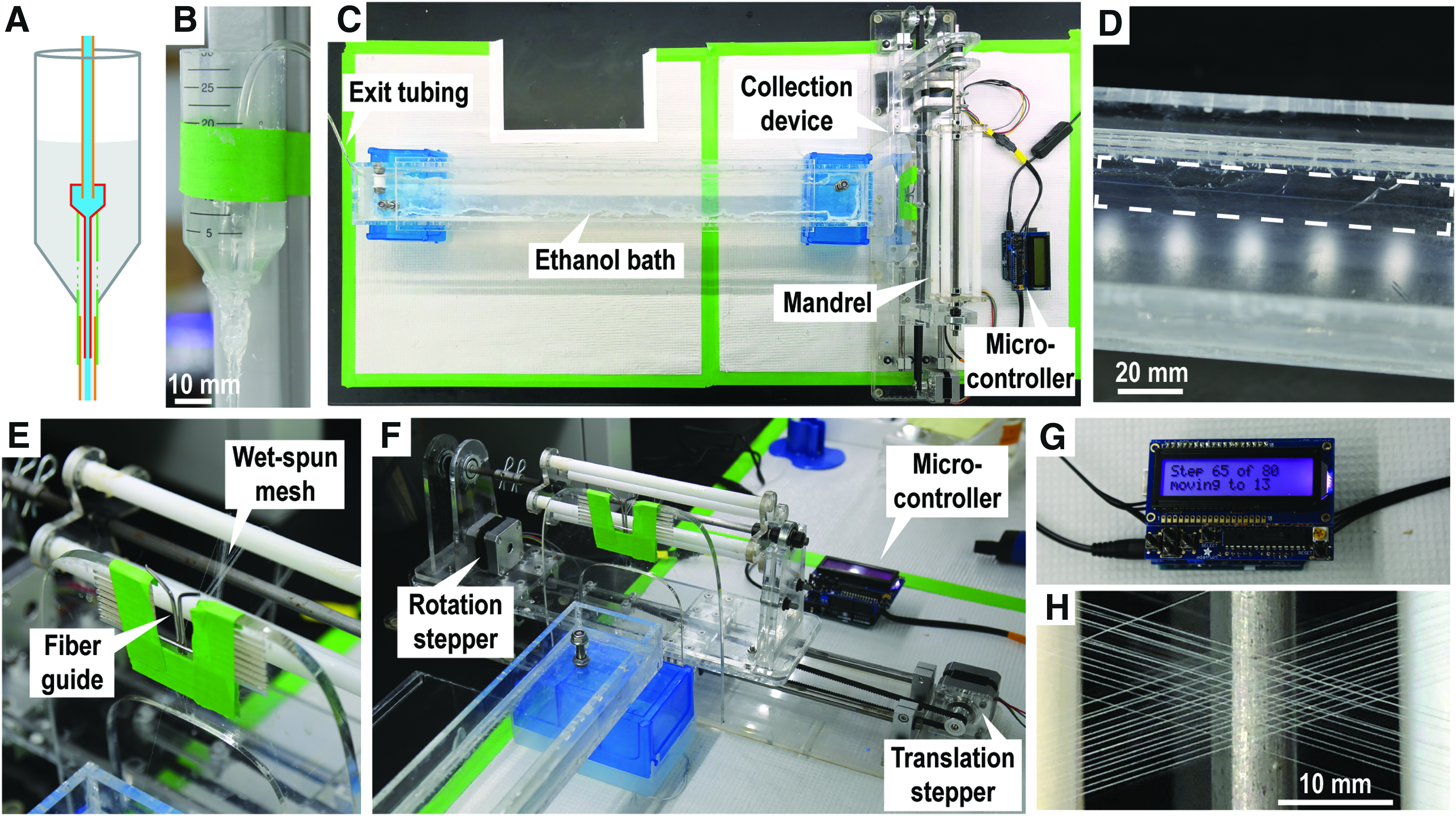
Fabrication and assembly of collection device and bath
All acrylic to acrylic connections between parts are made by sanding with 150 grit sandpaper and then gluing with cyanoacrylate adhesive. See Supplementary Figures S1–S6 for laser cutting designs and reference during assembly. Bolts and screws are referred to here by their thread size. Refer to Supplementary Table S1 for further parts' details.
Laser etch and cut all parts in the included laser design files (Supplementary Figs. S1, S3, and S5) out of ¼″ thick acrylic. Target etching depths are described in each of these documents. Specific power, speed, and dots per inch (DPI) settings will be laser dependent. A Universal Laser System PLS 6.75 equipped with a 75 Watt laser cuts through ¼″ acrylic cleanly with power, speed, and DPI settings of 100%, 1, and 1000, etches to a depth of 2.00 mm with settings of 100%, 10, and 1000, and etches to a depth of 3.00 mm with settings of 100%, 7, and 1000.
Prepare required machined components (see Supplementary Figs. S7 and S8 for details). Using a local machine shop to match required specifications is recommended. Steel capture frames are best cut by an industrial laser cutter followed by tapping the 1–72 threaded holes.
Assemble the fiber collector translator base by sanding the bottom edge of the translator stepper motor mount (Part D) and gluing into place on the translator base (Part A). Similarly, sand and glue two stacked rail shaft risers (Part B) into the matching etched slots in the translator base, with M5 bolts in place to ensure screw holes are aligned. Press fit and glue the two ball bearings into the openings in the pulley mounts (Part C), sand the bottom of the mounts, and glue into place with the pulley rod inserted to ensure alignment. Install the NEMA-17 stepper motor with four M3 bolts through the motor mount. Install the four linear rail shaft guides with M5 bolts. Attach the 5 mm GT2 timing pulley to the shaft of the translation stepper and the 8 mm GT2 timing pulley to the pulley shaft. Insert each 8 mm rail through each of the linear bearing platforms as well as one pair of rail guides. Tighten the rail guide screws to fix the rods in place. Attach the linear bearing mounts (Part F) and the translator platform (Part E) to the linear bearing platforms with 16 M4 screws. Prepare the timing belt grip (Part G) by cutting a 5 cm length of the GT2 timing belt and gluing into the etched trough, such that the teeth of the belt are exposed. Finally, install the translator timing belt by wrapping the remainder of the GT2 timing belt around the two translator timing pulleys, fixing the loose ends in place between the bottom of the translator platform (Part E), and the timing belt grip with four M4 bolts, cutting away excess.
Assemble the fiber collector rotator by stacking the inner mandrel support (Part J) between the two outer mandrel supports (Part I) such that the etched regions face each other. Fix in place with two M5 bolts before sanding the bottom and gluing into the matching slot on the rotator base (Part H). Press fit and glue the two ball bearings into the matching openings on the rotator stepper mount (Part K) and rotator shaft support (Part L). Install one Mcl and XL series timing pulley on the rotator stepper motor and attach to the rotator stepper mount with four M3 screws. Once the glue is dry, similarly sand the bottom and press fit these components into their matching slots on the rotator with the rotation drive shaft in place to ensure alignment. Install the other Mcl and XL series timing pulley on the rotation drive shaft and connect the two pulleys with the urethane timing belt.
Prepare one or more collection mandrels by press fitting the 37.5 cm long, 3/8″ diameter polytetrafluoroethylene (PTFE) rods into the four large openings of each of the mandrel caps (Part N). Teflon rods can be cut to size with a razor blade. Slide the mandrel caps, number 008 o-rings, shaft collars, and the end ball bearing onto the mandrel rod. Tighten the set screws of the shaft collars to fix the mandrel caps and ball bearing in place, as shown in Supplementary Figure S2, using the o-rings and shaft collars to hold the components in place.
Sand all four edges of the ethanol bath bottom (Part Q) as well as connection regions of the sides (Part P) and front and back (Part O). After sanding, clamp the bath together and glue by distributing cyanoacrylate adhesive along all connections. Once dry, seal all internal connections with silicone sealant to make the bath liquid tight.
Prepare the fiber guide support (Part M) by drilling two small holes 1 mm apart into the bottom of the top opening, sized to fit metal rods bent to form a narrow channel (Supplementary Fig. S2). Catheter IV needles (14 gauge, 2.1 mm OD) work well.
Finally, complete the fiber collector by attaching the fiber collector rotator to the translator with four M4 bolts through the precut holes. Attach the fiber guide by sanding the bottom and gluing into the matching etched slots. Mount a collection mandrel with the mandrel coupler and cotter pins. Position the bath at the end of the fiber collector. Decreasing the distance between the bath and the collection mandrel may reduce fiber breaks during mesh collection (Fig. 1). Adhesive feet can optionally be attached to the bottom of the fiber collector and ethanol bath.
Collagen fiber wet spinning and mesh organization.
Designing microfiber mesh protocols
Mesh patterns are designed using an open source flowchart software program called “Dia”, which allows for simple “click and drag” placement of lines in a graphical user interface. A provided Dia data file with mesh windows matching the dimensions of those on the collection mandrels facilitates mesh design in each of the four mesh windows (3.5 × 19 cm, Supplementary Fig. S2).
Mesh protocols designed in Dia are saved and exported as .dxf files (document exchange format). This format identifies the lines that compose the mesh design based on the x, y coordinates of their start and end points.
Mesh protocol .dxf files are translated into .ino Arduino format protocols using a custom Python script included with this publication. Multiple mesh designs can be translated into a single .ino file, which can be individually chosen during mesh collection.
Translated .ino format protocols are uploaded to the Arduino microcontroller with Motor Shield and RGB LCD Shield (Adafruit Industries, New York, NY) by USB for mesh fabrication. The Arduino microcontroller and Motor Shield provide a simple means of manipulating the two stepper motors, while the RGB LCD Shield provides a user interface during mesh collection.
Wet spinning collagen meshes
Collagen is wet spun into continuous microfibers using methods adapted from Caves et al, 2010. 38
Before the start of wet spinning, the outer surfaces of the four PTFE rods on the collection mandrel are coated with Neoweld Contact Cement (Springfield Leather Company, Springfield, MO) and allowed to dry for 20 min. This adhesive remains tacky for days after drying, holding fibers in place as they are collected, and maintaining mesh design fidelity.
Dissolved gases in the collagen solution may form bubbles that interrupt the continuous wet-spun fiber. If this problem arises, the collagen solution can be degassed in a vacuum chamber for 30 min before wet spinning.
The 64 × 7 cm bath (Fig. 1C) is filled with 650 mL of 70% ethanol, such that the depth in the bath is ∼1.5 cm, allowing the fiber and tubing to remain submerged during collection.
The buffer reservoir of the spinneret (Fig. 1A, B) is filled with high viscosity wet spinning buffer (HV-WSB, 34.5 mM potassium phosphate monobasic, 85.2 mM sodium phosphate dibasic, 135 mM sodium chloride, 29.9 mM HEPES buffer, and 8.57 mM polyethylene glycol MW 35,000). Buffer flow into the 1 m length of 1.6 mm inner diameter (ID) polyvinyl chloride (PVC) tubing is initiated by applying suction to the end of the tubing with a micropipette.
Once HV-WSB begins exiting the length of PVC tubing, 13 mg/mL collagen I in 0.1 M acetic acid (see Isolation of rat tail tendon type I collagen section) is extruded by syringe pump at a rate of 50 μL/min through a 0.4 mm ID spinneret prepared from a 22-gauge syringe needle into the same length of 1.6 mm ID PVC tubing, forming a coaxial flow system (Fig. 1B). Collagen precipitates from the 13 mg/mL solution as it travels the length of the tubing.
The continuous collagen fiber exits into the 70% ethanol bath, which washes away residual buffer solution and aids in drying the fiber.
The collagen fiber is picked up with forceps, dragged through the length of the bath, and a length of ∼20 cm is held in the air for ∼30 s or until the fiber is dry. The dry fiber is then threaded through the fiber guide (Fig. 1E) and onto the collection mandrel rods.
The collection protocol is initiated on the Arduino microcontroller (Fig. 1G). As the mandrel rotates, the fiber is pulled through the fiber guide and onto the mandrel in the prescribed pattern. Drying time between mandrel rotations is an important parameter that can be modified in the digital collection protocol.
Once the mesh protocol is complete, the mandrel is removed from the collection device for mesh capture.
Capturing and embedding wet-spun collagen meshes
Mesh capture frames are stainless steel rectangular frames with a window matching the desired size of the composite tissue construct (in this case, 3 × 9 mm). Paired with gaskets of similar dimensions, the frames hold the fibers in place during capture, embedding/casting, and cell culture (Fig. 2A).
Before mesh capture, 316 stainless steel frames, matching polydimethylsiloxane (PDMS) gaskets, 316 stainless steel screws (McMaster-Carr), and a matching hex key are autoclaved. Half of the stainless steel frames feature 1–72 threaded holes, while the other half feature larger 1.98 mm diameter through holes, allowing the frames to be screwed together with ¼″ long 1–72 threaded screws.
The frame alignment jig is thoroughly sprayed with ethanol and is placed inside a biosafety cabinet along with the autoclaved tools. The frame alignment jig is composed of an upper half and a lower half (prepared from laser cut ¼″ thick acrylic plastic) connected by a metal hinge (HIGHPOINT Model 161694W). PDMS plugs sized to fit the windows of the capture frames hold the frames in place during capture. The upper half of the jig features four through holes so that screws can be put in place while the frame is closed.
Aseptically, the stainless steel capture frames are loaded onto the press-fit PDMS plugs of the alignment jig with a frame with threaded holes on the lower half of the jig and a frame with through holes on the upper half of the jig.
The alignment jig is carefully positioned on either side of a mesh on the collection mandrel, with the region of interest aligned with the window of the lower capture frame. Once positioned appropriately, the jig is closed and held in place by the alignment jig magnets.
Screws are inserted through the holes in the alignment jig, and are screwed into place in the frame with the help of the hex key. Once all four screws are in place, the alignment jig can be opened and the captured mesh can be removed. Store captured meshes in a sterile vessel for up to 2 weeks before use (Fig. 2C).
Immediately before casting, while wearing sterile gloves, PDMS plugs are inserted into one capture frame of each frame set. The plugs should be sized to press-fit into the stainless steel windows. The frames are placed in an untreated six-well plate such that the plugs make contact with the bottom of the plate and keep the frames and bolts suspended.
A collagen hydrogel casting mix is pipetted through the open window in the stainless steel frame, using the tip of the pipette to guide the solution into the corners and edges of the window. In the case of acellular constructs, 2.0 mg/mL collagen I in PBS (pH 7.4) was used due to the poor handling properties of lower concentrations of collagen when uncompacted by resident cells. For cellularized constructs, 1.2 mg/mL collagen I in cell media is most effective. 39
Once casting is complete, the six-well plate is placed in a 37°C incubator for 30 min or until the collagen hydrogel has become opaque. Sufficient PBS (or cell media for cellularized constructs) is then added to each well to ensure that the fibrous constructs are covered.
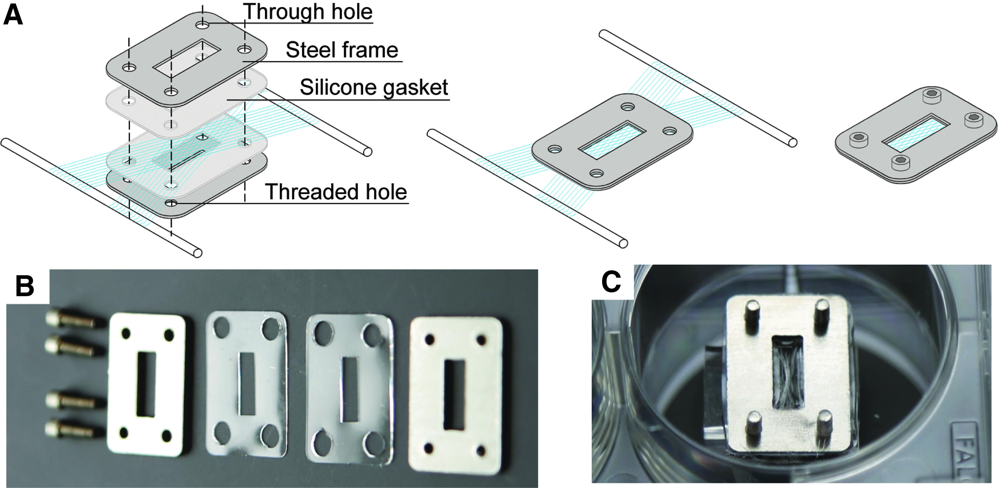
Collagen mesh capture frames and method.
Calibration of the collection device
Fabricated mesh fidelity relative to the Dia design file is dependent on the distance between rod positions indicated in the Dia design file. Device calibration is necessary to ensure that the fiber angles described in the mesh protocol design step match what is produced during wet spinning and mesh fabrication. The Dia files provided with this article (as Supplementary Data) have been calibrated to a rod spacing of 1240 units (corresponding to the y-axis tick marks in the Dia software), which is appropriate for the collection device as described in this study. Changes to the mandrel dimensions, fiber guide position, or choice of stepper motor will require adjusting or recalibration of this parameter. The following steps describe the calibration process:
Using the provided Dia file (which uses a rod spacing parameter of 1240 units), a mesh is created with known target fiber angle in terms of units. The provided 30° mesh angle protocol is a good starting point. The known mesh protocol is loaded onto the microcontroller and a set of meshes is fabricated, as described previously. Each mesh on the mandrel is imaged on a microscope with a low power objective. Fiber angle is analyzed by ImageJ using the Angle Tool. The angles of at least five overlapping fibers are measured for each mesh, and an overall empirical fiber angle mean is calculated. A new calibration factor is determined by multiplying the ratio of the target fiber angle over the empirical fiber angle by the rod spacing parameter (initially 1240). The rod spacing parameter should increase if the empirical angle is too acute and decrease if the empirical angle is too obtuse. Repeat steps b through d to ensure that the fiber angle is accurate.
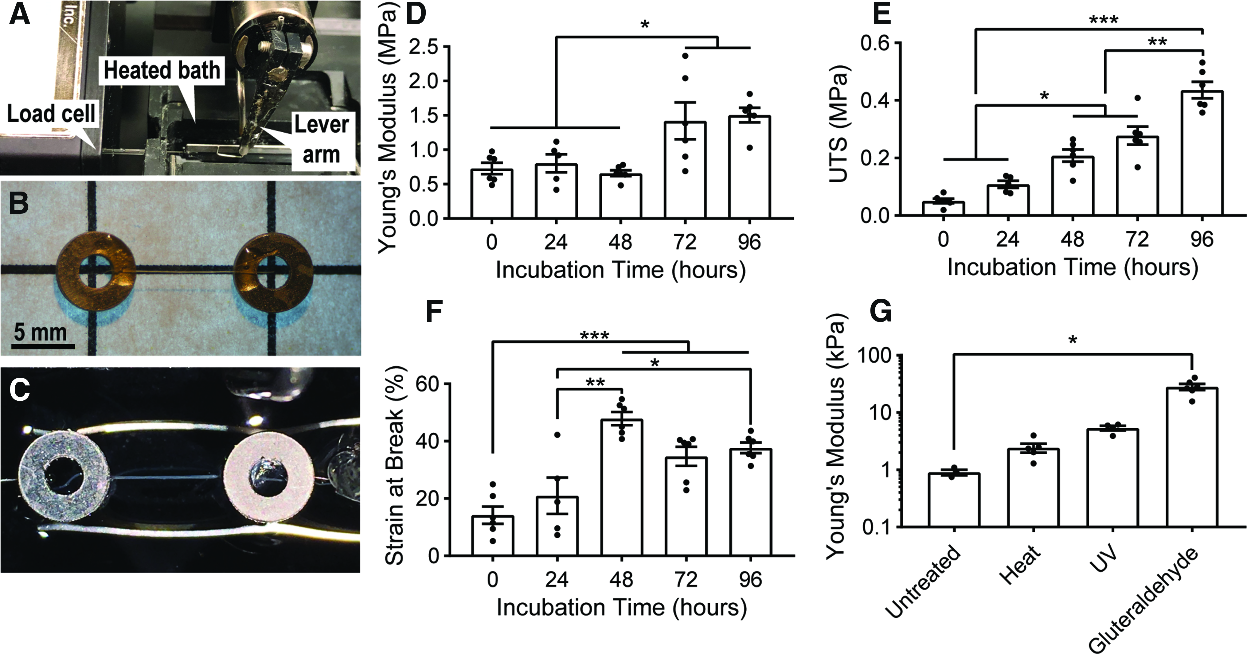
Mechanical analysis of individual collagen fibers
An adhesive is prepared by thoroughly mixing two parts acetone and one part polyurethane adhesive (Gorilla Glue). Thinning the polyurethane in this way decreases the viscosity such that the glue can be precisely placed by syringe. The prepared adhesive is loaded into a 3 mL syringe.
The chamfered tip of a 22-gauge syringe is cut, such that the new opening of the needle is fully perpendicular to the length of the needle, and this needle is attached to the syringe. This step facilitates precise adhesive placement.
A printed grid of known dimensions (rectangles 14 × 8 mm) is glued to a Petri dish. Stainless steel washers (ID 1.7 mm, OD 4.0 mm; McMaster-Carr) are carefully placed at each grid intersection to ensure sample regularity. Precise fiber length is measured later, immediately before testing using calipers.
Single wet-spun collagen fibers are cut to approximate size and each is laid across a pair of the steel washers. An antistatic tool (such as the Milty Zerostat, or an ionizing air blower) may assist in dissipating static electricity that can interfere with collagen fiber manipulation.
Under a dissection scope, the prepared syringe is used to deposit droplets of adhesive on the regions of fiber and washer overlap. The adhesive is allowed to dry overnight (Fig. 3B).
Once the adhesive is dry, fiber samples are placed in separate wells of a six-well plate, covered with 4 mL of PBS, and incubated at 37°C for various lengths of time before testing.
Fiber samples are carefully removed from the six-well plate and placed into the PBS-filled bath of a micromechanical testing apparatus (model 801C; Aurora Scientific; Fig. 3A, C), consisting of a temperature-controlled basin (maintained at 37°C), a hook connected to a lever arm, and a hook connected to a 5 mN load cell (model 403a; Aurora Scientific). One washer is placed around each of the two hooks, a preload of 0.1 mN is applied to each sample, and the initial sample length is measured with calipers.
Each fiber sample is preconditioned before testing by a triangular waveform pulling to 10% strain at a rate of 1% strain per second and declining at the same rate for a total of eight cycles.
After preconditioning, the 0.1 mN preload is reapplied, the new sample length is recorded, and each sample is pulled to break at a rate of 10% strain per minute. Strain at break, ultimate tensile stress (UTS), and Young's modulus (defined based on the linear region of the stress–strain curve, typically between 10% and 30% strain) is calculated from the pull-to-break trace for each sample.
Mechanical analysis of wet-spun collagen microfibers.
Mechanical analysis of fibrous collagen mesh composites
Acellular collagen mesh composites are prepared using 30° and 60° fiber meshes with 200 μm fiber spacing in stainless steel capture frames as described (see Capturing and Embedding Wet Spun Collagen Meshes section). Meshes are captured in two orthogonal orientations (referred to as longitudinal and transverse).
Mesh composites are incubated at 37°C in PBS for 6 days.
Mesh composites are isolated by disassembling the stainless steel capture frames. Aluminum t-clips (0.02 mm thick aluminum foil cut into the shape of a T, with a 0.8 mm diameter hole in the center of the longest tab) are attached to either end of the mesh composites by folding the wings inward. This method provides a means of griping the hydrogel constructs without causing damage.
Samples are mounted on to a micromechanical apparatus (model 801C; Aurora Scientific) with a 37°C bath filled with PBS by positioning the two right angle hooks through the holes of the aluminum t-clips (Fig. 3A). A preload of 0.1 mN is applied to each sample, and the initial sample length is measured with calipers.
Each composite sample is preconditioned before testing by a triangular waveform pulling to 10% strain at a rate of 1% strain per second and declining at the same rate for a total of eight cycles.
After preconditioning, the 0.1 mN preload is reapplied, the new sample length is recorded, and each sample is pulled to break at a rate of 10% strain per minute. Young's modulus (defined based on the linear region of the stress–strain curve, typically between 10% and 30% strain) is calculated from the pull-to-break trace for each sample.
Statistical analysis
All statistical analyses were performed in Prism 7 (GraphPad, Inc., San Diego, CA). For comparison between two groups, Student's t-tests were used. For comparisons of more than two groups, one-way ANOVA (analysis of variance) with multiple comparisons and Tukey's post hoc test were used. Error bars represent standard error of the mean unless otherwise noted. Group differences were considered statistically significant for p-values <0.05.
Results
Single fiber tensile mechanical properties increase with physiological incubation or crosslinking
To manipulate the mechanical properties of a composite material with embedded collagen microfibers, the mechanical properties of the fibers relative to the bulk hydrogel material are of critical importance. In addition, we hypothesized that collagen self-assembly would increase the stiffness and strength of the fibers in a physiological, aqueous microenvironment. Individual collagen microfibers were prepared using a mesh protocol with straight fibers spaced 400 μm apart. After spinning, fibers were cut from the mandrel and glued to stainless steel washers, as described previously in methods. Samples were incubated for 0, 24, 48, 72, or 96 h in PBS at 37°C. All samples were preconditioned and then tested in a constant strain rate pull-to-break test as described previously. It is important to note that the 0-h incubation group was allowed to hydrate in the testing bath for 10 min before analysis.
Before incubation treatment, hydrated collagen microfibers had a Young's modulus of 0.73 ± 0.08 MPa, UTS of 0.05 ± 0.01 MPa, and strain at break of 14.21% ± 3.02% (Fig. 3D–F). After incubation for 96 h, Young's modulus increased to 1.51 ± 0.11 MPa, UTS to 0.44 ± 0.03 MPa, and strain at break to 37.70% ± 1.85%, significant increases for all three metrics (p < 0.05). Evaluation at time points up to 15 days showed no further significant increases versus 96 h (data not shown). To explore the range of stiffness values that could be achieved by these fibers through established crosslinking methods, individual fiber mechanical samples were crosslinked either by dry heat for 1 h, 30 Watt ultraviolet light bulb (12 Watt output, 254 nm) at a distance of 75 cm for 1 h, or exposure to 25% w/v glutaraldehyde vapor for 24 h. Crosslinked fibers produced Young's modulus values as high as 28.1 ± 3.5 MPa (Fig. 3G).
Scanning electron microscopy and transmission electron microscopy imaging show collagen fibril self-assembly
To test our hypothesis that collagen self-assembly increases mechanical properties with incubation in physiological solution, we prepared bundles of overlapping wet-spun collagen microfibers using a collection protocol without any translational movement. Bundles of 20 fibers were collected and embedded in agarose to hold fibers together during incubation and processing. One group of collagen fiber bundles was immediately stained with 3% potassium ferrocyanide, 2% osmium tetroxide, and 1% uranyl acetate, embedded in EPON 812 resin, and sectioned for imaging, while a second group was incubated in a 10 cm dish filled with 10 mL of PBS at 37°C for 6 days before undergoing the same staining, blocking, and sectioning process. Both samples were imaged through serial block face (SBF) imaging, a technique that allows for layer-by-layer scanning electron microscopy (SEM) imaging to develop a 3D visualization of the sample volume on a Thermo Apreo VS SEM.
SBF imaging of unincubated fibers revealed only small-diameter collagen fibrils visible along the exterior of the wet-spun microfibers, while SBF renderings of the incubated fibers showed large, hierarchically organized collagen fibers (bundles ranging in diameter from 1 to 15 μm) branching out from the surface of the wet-spun microfibers, primarily oriented in the direction of the microfibers (Fig. 4A, B). Further transmission electron microscopy (TEM) imaging of the incubated fibers (Fig. 4C) found additional evidence of collagen self-assembly in clear D-banding phenomena with periodicity of 61.0 ± 2.8 nm, in line with values found in native collagen by other groups.40,41
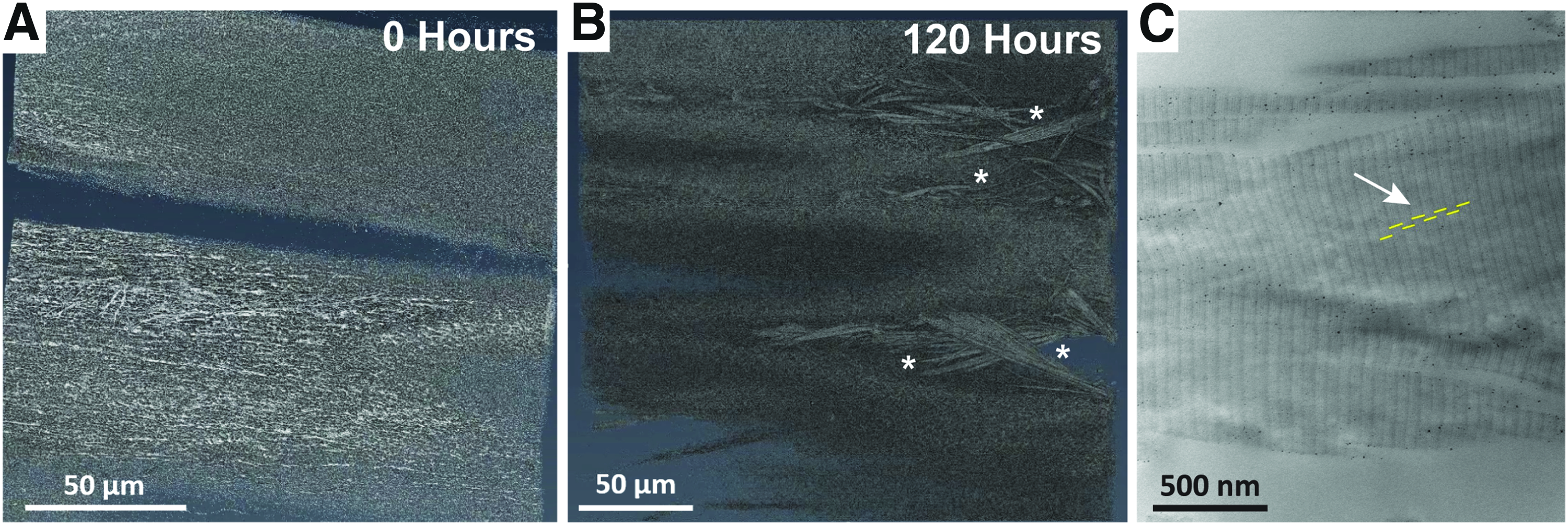
Electron microscopy imaging of unincubated and incubated collagen microfibers.
Differential scanning calorimetry analysis confirms collagen integrity after wet spinning
To confirm that the collagen maintained its native structure following the wet spinning process, we replicated the differential scanning calorimetry (DSC) methods of Zeugolis et al. 42 Briefly, collagen microfibers were collected following the protocol described above and then both these microfibers as well as unprocessed, lyophilized stock collagen were incubated in PBS for 24 h at 4°C to ensure full hydration. Samples were blotted dry on lint-free wipes and hermetically sealed in 40 μL aluminum pans. For each of the two groups, n = 3 samples were sequentially heated at a constant rate of 5°C/min from 15°C to 90°C on a TA Instruments DSC Q20. An empty aluminum pan was used as reference. The denaturation curve of each sample was analyzed based on three metrics: onset of denaturation temperature, peak denaturation temperature, and change in enthalpy (calculated as the area under the denaturation curve).
Both the collagen microfibers and the collagen stock solution exhibited change in enthalpy and denaturation temperatures consistent with native collagen molecular structure (Table 1). Importantly, these values are distinctly greater than those associated with collagen denatured by aggressive solvents and gelatin (ΔHD > −2.11, onset <37.07, and peak <40.36), 42 suggesting that no denaturation occurred during wet spinning. Indeed, the collagen wet spinning process is associated with an increase in onset and peak denaturation temperatures, as has been observed previously with extruded collagen fibers, suggesting increased molecular interactions between the triple-helical collagen molecules within wet-spun fibers.
Differential Scanning Calorimetry Analysis of Unprocessed Collagen and Collagen Microfibers
Mesh fidelity is dependent on fiber spacing
To evaluate the limits of fiber placement resolution, mesh protocols were prepared to deposit single, parallel fibers with spacing of 100, 200, or 400 μm. Both effective fiber spacing and fiber diameter were analyzed on the wet spinning mandrel (fiber diameter was considered because of the tendency of fibers to adhere to each other due to the accumulation of static electricity).
Results showed that at 100 and 200 μm spacing, static adhesion occurred, increasing the variability in both gap spacing and effective fiber diameter (Fig. 5A, B). Neighboring fiber adhesion was completely eliminated with 400 μm spacing, but lower spacing values may still be desirable to achieve higher fiber densities. Effective fiber diameter remained relatively consistent across the 100, 200, and 400 μm protocols, but variability decreased when adhesion was eliminated (57.89 ± 3.09, 49.79 ± 2.81, and 51.26 ± 2.28 μm, respectively). Accuracy and precision of overlapping fiber angles were evaluated. Angled fiber placement is the result of a number of rotation steps on the stepper motor responsible for translational movement, and therefore, placement accuracy is primarily dependent on calibration of the software (see Materials and Methods section). Conversely, calibration has no impact on placement precision, and this value is instead dependent on the inherent variability of the collection system and its constituent components, such as the precision of the stepper motor, flexion in the Teflon and acrylic components, and unevenness in the mandrel adhesive surface. Initial fiber angle data collected in the process of calibration (with the target of a 30° fiber angle) found a mean fiber angle of 34.4 ± 0.1 degrees when angles between overlapping fibers were measured by ImageJ. Following calibration, a mean fiber angle of 29.1 ± 0.1 was achieved (Fig. 5E). It should be noted that once properly calibrated, the collection system is able to produce meshes with any fiber angle, with the same degree of accuracy and precision. Repeated mesh fabrication of the same 30° fiber angle and 200 μm fiber spacing protocol demonstrated a high degree of consistency across fabrication batches (Fig. 5F).
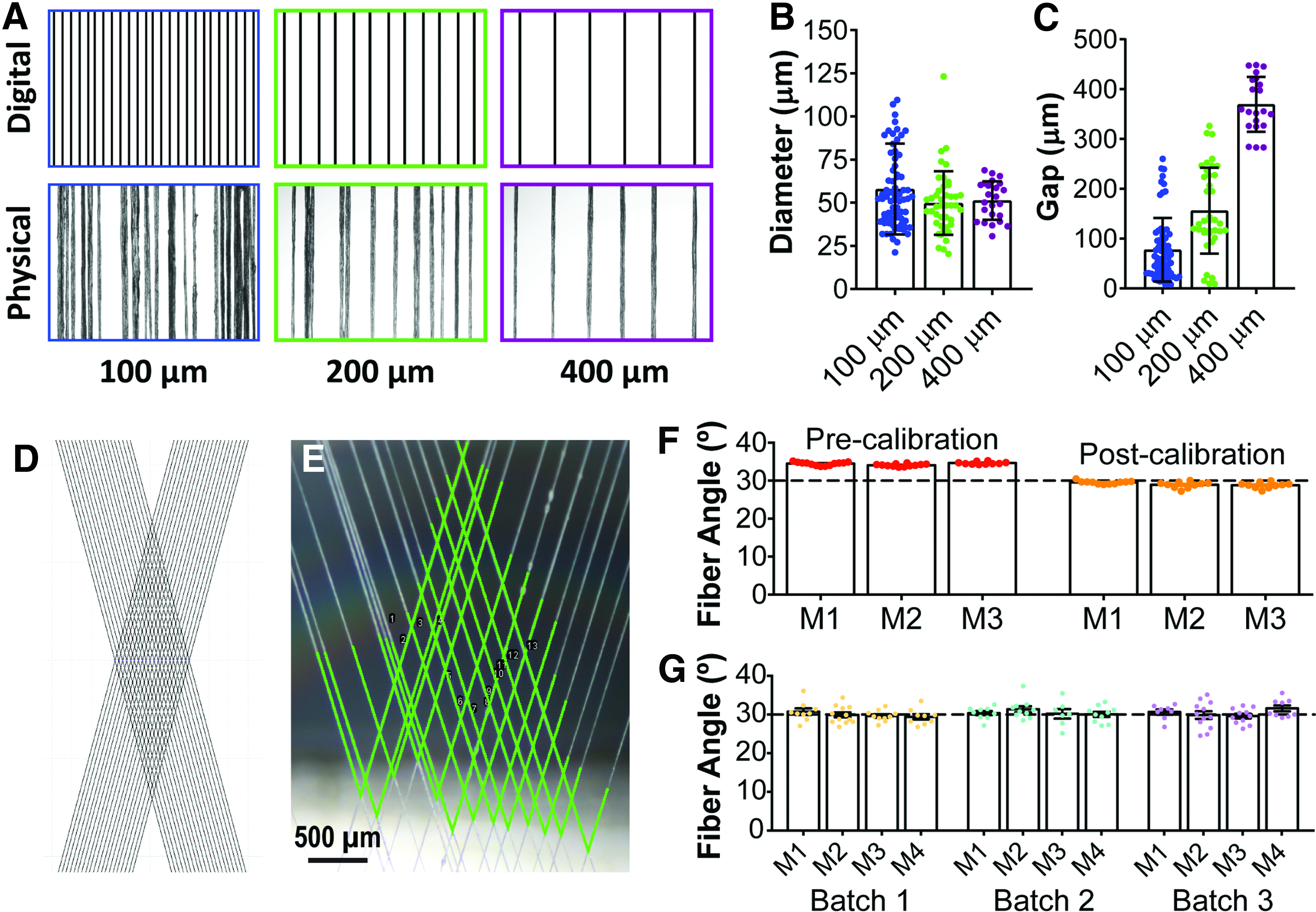
Evaluation of wet-spun mesh fidelity.
Mechanical testing of whole meshes demonstrates composite material anisotropy
To evaluate the impact of simple anisotropic collagen fiber patterns on mechanical anisotropy, collagen microfiber meshes with 30° and 60° fiber angles were prepared as described. Meshes were then captured in each of two orientations (diamond long axis parallel to either the long axis of the mesh window or the short axis of the mesh window, Fig. 6A). These meshes were embedded in 50 μL of a 2.0 mg/mL collagen solution, covered with PBS, and stored in culture conditions (37°C and 5% CO2). After 6 days, constructs were harvested and aluminum t-clips were attached to each end of the construct to facilitate mechanical testing. All samples were evaluated under the same conditions as the single collagen fibers, described previously.
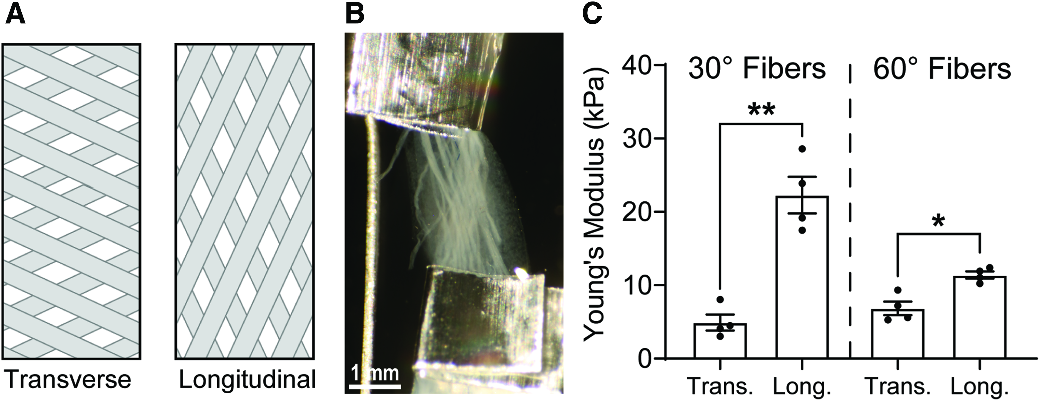
Bidirectional mechanical analysis.
Transverse composite fiber samples with a 30° fiber angle have a Young's modulus of 4.92 ± 1.09 kPa, while longitudinal samples have a Young's modulus of 22.28 ± 2.50 kPa, representing a statistically significant 4.5-fold change (p = 0.0007). Transverse fibers samples with a 60° fiber angle have a Young's modulus of 6.85 ± 0.93 kPa, while longitudinal samples have a Young's modulus of 11.40 ± 0.48 kPa, representing a statistically significant 1.7-fold change (p = 0.0048).
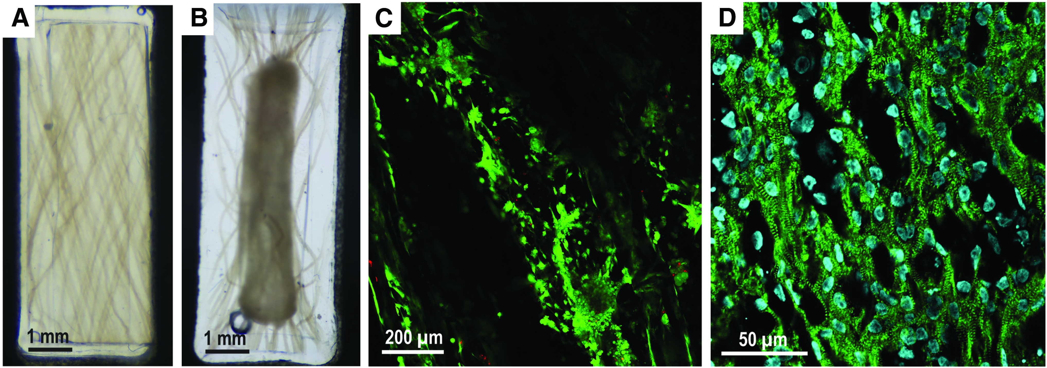
Fibrous scaffold composite tissues support resident cell viability
Collagen microfiber constructs were prepared with 50 μL of a casting mix of human induced pluripotent stem cell (hiPSC)-derived cardiomyocytes (15e6 cells/mL) in 1.2 mg/mL collagen I. Constructs were cultured at 37°C and 5% CO2, and were fed with cardiomyocyte maintenance media (RPMI+B27+Pen-Strep) every other day. After 6 days, cultured constructs were incubated with calcein AM and ethidium homodimer-1 (Live/Dead Assay; Invitrogen) and imaged on a confocal microscope (Olympus FV3000). Replicate constructs were fixed, embedded in frozen blocks, sectioned, and stained with α-actinin, a cardiac marker, and DAPI nuclear stain.
Gross images of constructs after 96 h of culture demonstrate visible construct compaction, the process through which resident cells remodel the hydrogel microenvironment. Constructs compacted to 38.4% ± 2.77% of their initial visible area after 96 h of culture (n = 6) with no failure to compact and form a tissue. Fluorescent live/dead staining revealed dense, viable cardiomyocytes throughout the tissue (Fig. 7C). Immunohistochemistry confirmed the cardiomyocyte phenotype of seeded cells in the form of banded α-actinin staining of myofibril z-discs (Fig. 7D).
Cells compact the collagen microfiber scaffold to form viable engineered tissue.
Discussion
Over the past decade, the critical role of a fibrous ECM microenvironment in cell and tissue function has increased interest in the development of more sophisticated scaffold materials that can better emulate the diverse properties of native, fibrous ECM. Herein, we describe a highly versatile platform for producing scaffolds, tissues, and biomaterials composed of collagen microfibers embedded in a bulk hydrogel material, with bespoke collagen architectures and mechanical properties. By using only tools fabricated at relatively low cost and open source software, we have designed this platform to be accessible to as many researchers as possible because we believe that the applications in tissue engineering and biomaterials research are vast. As we show in this study, embedded collagen microfibers offer a flexible platform for this research due to the availability and relatively low cost of isolation from source tissues, in addition to the high density of cell adhesion sites, robust mechanics, and native molecular structure.
Evaluation of the stability or degradation of a new biomaterial in physiological conditions is critical to understanding material performance in biomedical applications. Importantly, individual collagen microfibers showed more robust mechanical performance with significantly increased Young's modulus, UTS, and strain at failure, with increasing incubation time in physiological PBS at 37°C up to 4 days (Fig. 3D–F). After 96 h of incubation, the Young's modulus of the noncrosslinked fibers increased to 1.51 ± 0.11 MPa orders of magnitude greater than both conventional collagen hydrogels used for tissue engineering (0.5–12 kPa39,43) as well as most native soft tissues.44–47 In addition, the tensile strain at failure after 96 h of incubation (37.70 ± 1.85) exceeds the tensile strain regularly experienced by many native soft tissues (including cardiac muscle 48 and tendon 49 ). Together, these properties provide a mechanical justification for the utility of collagen microfibers as a reinforcing material in a composite soft tissue scaffold.
We hypothesized that molecular self-assembly of collagen could increase mechanical performance and evaluated this hypothesis by electron microscopy. SEM imaging of unincubated and 5-day incubated collagen microfibers confirmed larger collagen fibrils after incubation, particularly at the surface of the collagen microfibers (Fig. 4B). Further TEM imaging confirmed fibril self-assembly with characteristic collagen D-banding at 61.0 ± 2.8 nm periodicity, which agrees with values reported in the literature for native collagen.40,50 DSC evaluation of hydrated collagen microfibers demonstrated denaturation characteristics consistent with those described in the literature for triple helical collagen. Together, these findings demonstrate that the molecular integrity of the purified collagen has been maintained throughout the isolation and wet spinning process. While previous groups have reported similar findings regarding wet-spun collagen microfibers, the modifications to previously described protocols mandated by the mesh collection and embedding strategy described herein prescribed this validation.38,51 Importantly, the molecular self-assembly that occurs within the collagen microfibers also demonstrates that (a) strength can be increased without chemical crosslinking and (b) the scaffold is composed of molecular building blocks that can be utilized and remodeled by cells in tissues.
Implementation of a composite fiber scaffold for regenerative medicine and tissue engineering requires evaluation of the mesh itself, the composite acellular material, and cell viability upon contact with the biomaterial. Mesh fidelity analyses demonstrate a high degree of both accuracy and precision in fiber angle, and minimal variability in fiber angle between fabrication batches (Fig. 4). Mesh fidelity was reduced in meshes with fibers spaced less than 400 μm apart due to static attractions between the fibers during placement, causing fibers to adhere to a neighboring fiber. However, this level of pattern corruption may be acceptable depending on the application. For example, closer fiber spacing may be desirable for applications in tissue scaffolds. Scaffolds composed of fibers ∼400 μm apart would ensure that no cell in the fiber plane is more than 200 μm from a fiber with a high degree of homogeneity. Conversely, targeting 200 μm spacing with the approach described herein would ensure that a majority of cells are within 100 μm of a fiber (shown to increase cellular alignment 35 ) at the cost of overall mesh uniformity. The impact (positive or negative) of this heterogeneity will depend largely on the intended application and associated tolerances.
With 400 μm spacing, effective dry fiber diameters were fairly consistent (51.26 ± 11.16 μm, mean ± SD), but this variability also increased when spacing became small due to electrostatic interactions that drew adjacent fibers together (81.85 ± 80.38 for 100 μm, mean ± SD). It should be noted that similar collagen wet spinning methods have been used to produce collagen fibers with dry diameters ranging from 20 to 150 μm, 38 but the fiber diameter presented in this study is associated with the wet spinning conditions that were found to minimize fiber breaks during mesh fabrication.
One major advantage of a bespoke fiber architecture is the ability to design anisotropy into the ECM scaffold, such as is found in cardiac muscle, for example. Mechanical analysis performed on acellular 30° meshes captured in both longitudinal and transverse orientations demonstrated the presence of mechanical anisotropy in composite constructs evidenced by an ∼4.5:1 ratio between Young's modulus in the longitudinal orientation relative to the transverse orientation, while 60° meshes exhibited a ratio of ∼1.7:1 (Fig. 5). Young's modulus of the 30° composites in the longitudinal direction (22.28 ± 2.50) approached that of native myocardium (30.80 ± 2.71 kPa 39 ), demonstrating that this fabrication method can produce composite materials that approach the passive stiffness of native tissues, before compaction by resident cells, which is anticipated to further increase the mechanical properties. Perhaps more importantly, the ratio of longitudinal to transverse Young's modulus values for the 60° composites was found to be 1.7:1, which closely approximates the range of anisotropic ratios reported in the literature for left ventricular native myocardium (∼1.4:1 to ∼2.0:1).39,52,53
Beyond the simple scaffold patterns that were evaluated in this study for the purpose of characterizing the capabilities and limitations of this platform, many other sophisticated designs can be created for a range of applications (Supplementary Fig. S9). Arrays of aligned collagen microfibers can be created to emulate native tendon, and nonrectangular shapes can be created to emulate both the structure and mechanics of diverse tissues, such as valve leaflets. Finally, we have prepared meshes with up to four layers (Supplementary Fig. S9), resulting in a hydrated mesh thickness of ∼400 μm, permitting the fabrication of organized, dense fibrous tissues that approach/exceed the diffusion limits for engineered tissues.54–56 Additional layers or modular assembly may enable thicker tissues if integrated with perfusion of nutrients in vitro or a blood supply by vasculature in vivo.
Fibrous collagen composite scaffolds are viable tissue scaffolds as we demonstrate with the culture of hiPSC-derived cardiomyocytes on meshes prepared in both parallel and 30° fiber configurations (Fig. 6). Resident cells rapidly remodeled the bulk hydrogel and exerted stress on the collagen microfibers as shown by their deformation (Fig. 6A, B). Fluorescent live/dead staining of cellularized constructs showed a high density of viable cardiomyocytes and few dead cells throughout the tissue (Fig. 6C), and immunohistochemistry confirmed that the resident cardiomyocytes maintained a striated morphology (Fig. 6D).
Despite the wide variety of scaffold technologies available to tissue engineers today, a compromise must often be made between the desirable cell adhesion and remodeling responses of natural polymers (like triple helical collagen), and the ease of production, mechanical robustness, and molecular durability of synthetic polymers, which have rapidly advanced novel fabrication technologies like 3D printing and electrospinning. In many cases, the solution takes the form of natural and synthetic copolymers and blends, such as polycaprolactone-collagen, collagen/polylactic acid, and collagen/poly(lactic-co-glyocolic acid),57–60 to benefit from the mechanical integrity of synthetics and the cell-binding sites of collagen. The distinct advantages of incorporating wet-spun collagen microfibers into scaffolds presented herein are that it offers precise, customizable structural control and physiologically relevant mechanical robustness without any compromise in terms of cell adhesion site density, remodeling response, and immune response by simply using unadulterated collagen in both a structurally reinforcing fiber compartment and bulk hydrogel. These benefits are amplified by the low barrier to entry required for the automated approach provided in this study.
Automated fabrication systems with high accuracy and precision offer substantial benefits over manual fabrication and assembly methods for both research and therapeutic applications. Even at the bench scale, improvements to reproducibility and time costs are extremely valuable. However, the typically high cost and complexity of automated fabrication for tissue engineering has limited the reach of these technologies in research settings. The simple method of mesh design and automated fabrication presented herein extends the advantages of automated biomaterial fabrication to a wide variety of applications and to users with any level of expertise to increase adoption of the collagen wet spinning method. Unlike electrospinning methods,61,62 collagen wet spinning is minimally affected by environmental parameters (such as temperature, humidity, and airflow) and therefore can be performed much more cheaply and easily on an open benchtop. Alternatively, minimal modification would be required to adapt the process and device described herein for mesh fabrication in a biosafety cabinet to eliminate bioburden concerns. Indeed, the versatile methods described herein may serve as a strong platform for direct application in both tissue engineering and biomaterial research, and also to support further innovation in automated fabrication of customizable collagen materials.
Conclusions
Collagen microfiber meshes are a desirable platform for tissue engineering and biomaterial research due to the ability to tune both the mechanical properties of individual fibers as well as the composite as a whole with a material—collagen type 1—that has inherently excellent cell adhesion and remodeling properties. To facilitate the use of this technology, we have successfully created a system for preparing composite collagen microfiber scaffolds and biomaterials with a broad range of mechanical properties and applications. By employing low-cost rapid fabrication techniques and accessible software tools, our system serves as a customizable, automated, biomaterial fabrication platform with equally broad accessibility. Adoption of bespoke collagen microfiber scaffolds will benefit biomaterial engineering and fulfill a need for fully natural fibrous materials with defined architecture.
Footnotes
References
Supplementary Material
Please find the following supplemental material available below.
For Open Access articles published under a Creative Commons License, all supplemental material carries the same license as the article it is associated with.
For non-Open Access articles published, all supplemental material carries a non-exclusive license, and permission requests for re-use of supplemental material or any part of supplemental material shall be sent directly to the copyright owner as specified in the copyright notice associated with the article.