
Abstract
Objectives:
A vascular supply network is essential in engineered tissues >100–200-μm thickness. To control vascular network formation in vitro, we hypothesize that capillarization can be achieved locally by using fibers to position and guide vessel-forming endothelial cells within a three-dimensional (3D) matrix.
Materials and Methods:
Biofunctionalization of poly-(L-lactic acid) (PLLA) fibers was performed by amino-functionalization and covalent binding of RGD peptides. Human foreskin fibroblasts (HFFs) and human umbilical vein endothelial cells (HUVECs) were seeded on the fibers in a mould and subsequently embedded in fibrin gel. After 9–21 days of coculture, constructs were fixed and immunostained (PECAM-1). Capillary-like structures with lumen in the 3D fibrin matrix were verified and quantified using two-photon microscopy and image analysis software.
Results:
Capillary-like networks with lumen formed adjacent to the PLLA fibers. Increased cell numbers were observed to attach to RGD-functionalized fibers, resulting in enhanced formation of capillary-like structures. Cocultivation of HFFs sufficiently supported HUVECs in the formation of capillary-like structures, which persisted for at least 21 days of coculture.
Conclusions:
The guidance of vessel growth within tissue-engineered constructs can be achieved using biofunctionalized PLLA microfibers. Further methods are warranted to perform specified spatial positioning of fibers within 3D formative scaffolds to enhance the applicability of the concept.
Introduction
B
In the field of tissue engineering, several strategies have been proposed for the creation of a vascular supply network within engineered tissues and organs. Extrinsic (in vivo) vascularization and pre-(in vitro)-vascularization are the two principle strategies that are currently being pursued to vascularize tissue-engineered constructs. Extrinsic vascularization is the ingrowth of the host vessel system into the tissue-engineered construct in vivo, whereas a prevascularization includes the preforming of capillary-like structures inside the tissue-engineered construct in vitro. It has been shown by several groups that prevascularization in vitro augments the nutritional supply of cells compared with extrinsic vascularization alone in vivo.2–4 These findings have resulted in the development of several distinct approaches for prevascularization of scaffolds in vitro.5–7 In the majority of these cases, cellular cocultures are employed to enhance the potential for capillarization as a consequence of cellular cross-talk 8 and extracellular matrix (ECM) support. 9
Another approach of prevascularization is the repopulation of the pre-existing decellularized matrices with endothelial cells, resulting in a more natural, but established, orientation of the vessel tree. 10 Unfortunately, “controlled” capillarization using the aforementioned strategies is difficult, particularly when considering that all cells in vivo will require capillary support within a close proximity (100–200 μm). To achieve this task, a combination of a separate tubular-guiding material and a surrounding scaffold needs to be realized in order to guide appropriate development of the interconnected capillary-like tubular network with adequate proximity of these tubular structures to all cells throughout the surrounding scaffold.
Microfibers have been proposed as tubular guidance structures that can orientate vessel-forming cells and guide the formation of a tubular-like network. The orientation and directional migration of endothelial cells adjacent to microfibers has already been demonstrated by Hadjizadeh and Doillon 11 and Sukmana and Vermette 12 using coculture systems. Unfortunately, the system is too simplistic, with the fibers orientated parallel to each other in a single plane within a fibrin gel. Additionally, the fiber material employed is not biodegradable and there is no direct contact between the supportive cells and the vessel-forming cells to stabilize the resulting network.
In this study, we present a technique to seed both endothelial and supportive cells onto biodegradable, biofunctionalized extruded poly-(L-lactic acid) (PLLA) microfibers within a fibrin matrix. We hypothesized that RGD biofunctionalization of the microfibers will improve attachment of the coculture cells, leading to enhanced development of capillary-like structures with lumen adjacent to the fibers.
Materials and Methods
Cell culture
Umbilical-cord-derived cells were obtained in accordance with the human subjects approval of the ethics committee (votum of the local ethics committee: No. EK 2067). The approval includes the use of umbilical-cord-derived cells for blood vessel development in vitro. Participants provided their written consent to participate in this study. Umbilical cords were kindly provided by the Department of Gynaecology at the University Hospital in Aachen.
For isolation of human umbilical vein endothelial cells (HUVECs), human umbilical cords were harvested under sterile conditions. After washing the umbilical cords with phosphate-buffered saline (PBS; PAA), HUVECs were removed using 1 mg/mL collagenase for 30 min at 37°C (type II; Gibco). The isolated endothelial cells were reseeded on 2% gelatin-precoated tissue culture flasks (T75; Greiner) in endothelial basal medium (Lonza) supplemented with EGM-2 supplements (Lonza). The medium was changed every 4 days. To check their purity, HUVECs were stained for PECAM-1 and alpha-SMA (see Fig. 1B, C).
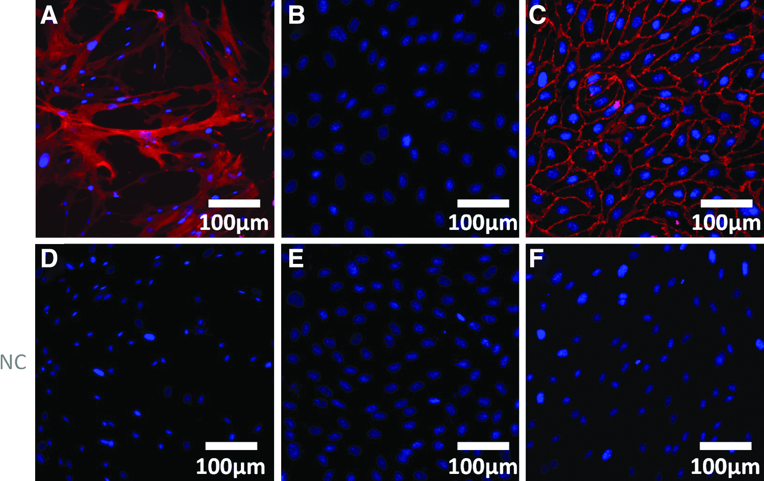
Characterization of human umbilical vein endothelial cells (HUVECs);
For the isolation of human umbilical artery smooth muscle cells (HUASMCs) as a positive control in α-SMA staining, umbilical arteries were minced into 1-mm rings for primary explant culture in Dulbecco's modified Eagle's medium (DMEM; Gibco) supplemented with 10% fetal bovine serum (FBS; PAA) and 1% gentamycin solution (Carl Roth).
Human dermal foreskin was harvested from juvenile patients in accordance with the human subjects approval of the ethics committee (votum of the local ethics committee: EK23711). The approval includes the use of cells for blood vessel development in vitro. Participants provided their written consent to participate anonymously in this study. For isolation of human foreskin fibroblasts (HFFs) as supportive cells for angiogenesis, human foreskin was cut into tissue strips followed by bathing in dispase (2.5 U/mL; Gibco) and streptomycin/penicillin (Gibco) for 18 h at 4°C. After separating the epidermis from the dermis, HFFs were isolated by digesting the dermal pieces with 1 mg/mL collagenase for 1 h at 37°C (type II; Gibco). After complete digestion, the solution was filtered through a 100-μm-pore-sized filter (Becton Dickinson) and centrifuged (400 g, 10 min). The cell pellet was resuspended in DMEM (Gibco) and 10% FBS (PAA). The medium was changed every 4 days.
PLLA microfibers and functionalization
PLLA was synthesized at the Institute of Textile Technology and Process Engineering (Denkendorf) by a common ring-opening procedure. 13 Briefly, PLLA microfibers were processed by thermoplastic extrusion and stretched to a 40-filament yarn, with each filament having a diameter of 10 μm. The yarn was loosely bundled into a 79-multi-ply yarn with a diameter of ∼8 mm. The fiber bundle was clamped at both ends to form a ring-like structure. The fiber interstices were in the range of 100–200 μm. 14
To functionalize the PLLA microfibers, amino groups were immobilized on the fiber surface using NH3-plasma in a low-pressure and -temperature microwave plasma machine (AK330; Roth & Rau). The optimal parameters to obtain the highest and most homogenous amine group content were 450 W, 30 sccm, 40 Pa, and 4 min, as demonstrated by X-ray photoelectron spectroscopy (XPS), FITC staining, and sessile drop contact angle measurements. 15
After amino-functionalization, free isocyanate groups were introduced by incubating the amino-functionalized fibers for 5 days with hexamethylene diisocyanate (HDI; Sigma Aldrich) spacer in absolute diethyl ether (1:10, w/w). After extraction in a Soxhlet extractor under nitrogen in absolute diethyl ether for 4 h and drying in a vacuum, free isocyanate groups were generated on the amino-functionalized PLLA fiber surface. To couple RGD to the isocyanate groups of the HDI spacer molecules, RGD (50 μg/mL) was dissolved in NaHCO3 buffer and incubated with the HDI fibers overnight (4°C). Subsequently, the fibers were washed with NaHCO3 and distilled water, air-dried, and stored at 4°C.16,17 The process of fiber functionalization is depicted in Figure 2.
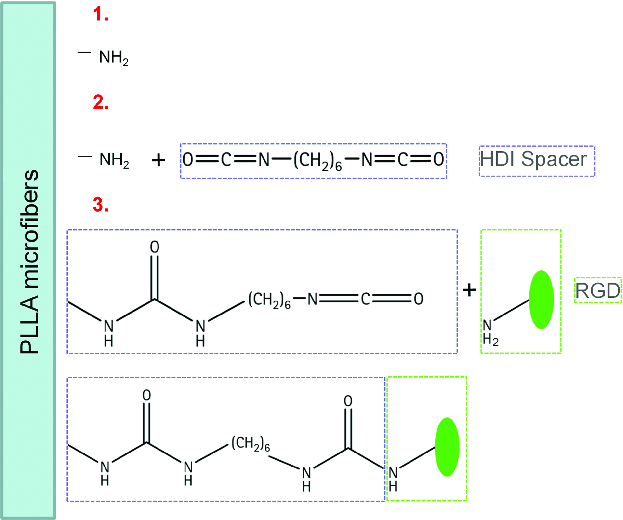
Covalent coupling of RGD via a spacer to the poly-(L-lactic acid) (PLLA) microfiber surface; (1) fiber surface is activated via nitrogen plasma; (2) HDI spacer can be directly coupled to available amino groups (−NH2) on the surface; (3) the bioactive molecule RGD is coupled to the spacer. Color images available online at www.liebertpub.com/tea
Cytotoxicity assays
Adenylate kinase release (cytotoxicity assay)
The indirect cytotoxic effects of PLLA and biofunctionalized PLLA on the HFFs and HUVECs were evaluated using a commercial assay kit based on the release of adenylate kinase (AK) from lysed cells (ToxiLight Bioassay Kit Non-Destructive Cytotoxicity assay; Lonza). The test was performed according to a standard protocol described elsewhere. 18 Briefly, HFFs or HUVECs were cultured in a 96-well plate at a density of 1×10⁴ cells/well in standard medium (DMEM and 10% FBS for HFFs; EGM-2 for HUVECs). After 48 h of preculturing, medium was replaced with test medium (appropriate medium without FBS, preincubated with nonfunctionalized and biofunctionalized PLLA for 72 h at 37°C). The amount of AK released into the test medium after regarding 2, 4, 6, and 9 days of incubation was determined by measuring the absorbance of test samples with a multiwell spectrophotometer (Tecan Infinity M200; Tecan Deutschland GmbH). A positive control was developed by freezing the cells, while standard cell culture medium, which was not in contact with the material, served as a negative control. Each assay was performed in quintuplicate.
XTT assay (proliferation assay)
The indirect effect of the fiber material, PLLA, and the biofunctionalized PLLA on cell proliferation was determined using the (XTT) {sodium 3-[1-(phenylaminocaronyl)-3,4-tetrazolium]-bis(4-methoxy-6-nitro) benzene sulfonic acidhydrate} assay [Cell Proliferation Test Kit II (XTT); Roche Diagnostics GmbH] as described elsewhere. 18 Briefly, HFFs or HUVECs were seeded in a 96-well plate (1×10⁴ cells/well) in DMEM culture medium (+10% FBS or EGM-2) and incubated under standard conditions (37°C, 5% CO2). After 48 h of preculturing, the medium was replaced with test medium (DMEM+10% FBS for HFFs and EGM-2 for HUVECs, preincubated with nonfunctionalized or RGD-functionalized PLLA for 72 h at 37°C). Standard cell culture medium (DMEM+10% FBS or EGM-2), which was not in contact with the fibers, served as a negative control. DMEM with reduced supplementation of FBS (5%) was used as positive control for HFFs and EGM-2 without FBS for HUVECs. Cell proliferation was analyzed after 2, 4, and 6 days using the XTT assay. About 5 mL of XTT Labelling Reagent was mixed with 100 μL of Electron Labelling Reagent. After mixing, 50 μL of XTT solution was added to each test well, and the cells were incubated for 2 h at 37°C. The optical density was measured at 475 nm using a spectrophotometer (Tecan Infinity M200). Each assay was performed in quintuplicate.
Coculture
HFFs (passage 8) and HUVECs (passage 3) were cultured in both two-dimensional (2D) and three-dimensional (3D) coculture assays to control their performance. The 2D assay was performed by seeding 1–3.5×10⁴ HFFs in DMEM+10% FBS into 96-well plates. After 48 h, medium was exchanged with an HUVEC suspension (1–3.5×10⁴ cells/mL) in Vasculife VEGF medium (Lifeline Cell Technology). The culture medium was changed every 3–4 days. On day 11, cells were fixed with methanol (−20°C) and immunostained with PECAM-1 or α-SMA (both Sigma Aldrich) and DAPI nuclear stain (Invitrogen).
For the 3D assay, HFFs and HUVECs were mixed at a concentration ratio of 1:2 (3×10⁵ to 6×10⁵) according to previous results and the literature 19 and embedded in 100 μL of fibrin gel as described below. Gels were cultivated in Vasculife VEGF medium for 9 days. The culture medium was replaced every 3–4 days. After 9 days of coculture, cells were fixed and immunostained as per the 2D assay.
Biofunctionalized fiber assay
For the biofunctionalized fiber assay, fibers were weighed, washed in PBS, and added to 2-mL tubes (Eppendorf). Supportive HFFs were prestained with Calcein-AM (AAT Bioquest) for 30 min at 37°C (5% CO2). After staining, HFFs (7×10⁵) in DMEM+10% FBS were poured into the 2-mL tubes, followed by mixing on a roller mixer (Hecht-Assistent RM5; Karl Hecht und Co). Cell distribution was optically monitored via light microscopy (Zeiss AxioImager D1; Jena). The seeded fibers were stored in an incubator (37°C, 5% CO2; Binder CB210) for 2 days according to the 2D coculture assay. Subsequently, medium was replaced with an HUVEC suspension (7×10⁵) in Vasculife VEGF medium and distributed by a roller mixing procedure (Hecht-Assistant RM5). The preseeded fibers were returned to the incubator at 37°C and 5% CO2. After 1 day of incubation, fibrin gel was moulded around the cocultured fibers. Preseeded fibers were cultivated like 3D coculture systems for up to 21 days. After 9–21 days of coculture, cells were fixed and immunostained as per the 2D assay.
Fibrin gel fabrication
Fibrinogen was prepared as previously described. 20 Briefly, fibrinogen (Sigma-Aldrich) was dissolved for 1.5 h in purified water and dialyzed against 4 L of Tris-buffered saline (TBS) in 6000–8000 MW dialysis tubing (Novodirect) overnight. After sterile filtration, the fibrinogen concentration was estimated by measuring the absorbance at 280 nm using a spectrophotometer (Spectronic Genesys TM6; ThermoFisher). The final concentration of fibrinogen solution was adjusted to 10 mg/mL with TBS. The fibrin gel around the fibers (100 μL total) consisted of 50 μL of fibrinogen solution (10 mg/mL), 35 μL TBS, and 7.5 μL of 50 mM CaCl2 (Sigma) in TBS. Gel polymerization was initialized by adding 7.5 μL of thrombin solution (40 U/mL; Sigma) to each well.
Immunohistochemistry
For characterization, HUVECs were stained with PECAM-1 (1:100; P8590 Sigma) and α-SMA (1:400; Sigma) antibodies. Prior to staining, cells were fixed with ice-cold methanol for 20 min and 100 μL of each antibody diluted in blocking buffer was added to each well and incubated for 1 h at 37°C. After washing with blocking buffer for 5 min, 100 μL of the AlexaFluor594-conjugated goat anti-mouse secondary antibody (1:400; Invitrogen) was added for 1 h at 37°C. As a positive control, HUASMCs have been used.
In fibrin gels, cells were fixed after 9–21 days and the whole gel was immunostained with the endothelial marker PECAM-1. The primary PECAM-1 antibody (1:100; Sigma) was diluted in blocking buffer. About 120 μL of the diluted antibody was added to each well and stored in an incubator for 2 days (37°C). After washing with blocking buffer overnight, 100 μL of the AlexaFluor594-conjugated goat anti-mouse secondary antibody (1:400; Invitrogen) was added for 2 days at 37°C.
For cryosections, thawed samples were fixed with paraformaldehyde (4%) and washed with PBS (three times, 5 min each), followed by blocking their nonspecific binding sites with 5% normal goat serum for 1 h (DAKO). Sections were incubated for 1 h at 37°C with the mouse anti-PECAM-1 primary antibody (1:400; Sigma). Sections were then incubated for 1 h at 37°C with AlexaFluor594-conjugated goat anti-mouse secondary antibody (1:400; Molecular Probes). For 2D coculture systems, samples were fixed with methanol (−20°C) for 30 min and stained in accordance with the cryosection procedure described previously.
Cell nuclei were counterstained using DAPI nucleic acid stain (Invitrogen). As negative controls, samples were incubated only in diluent and secondary antibody (see Figs. 1D–F and 5E–H). Endothelial cells alone or adjacent to biofunctionalized microfibers in fibrin gel served as a positive control (see Figs. 1C and 5C).
Sections were viewed using an epifluorescence microscope (AxioObserver; Carl Zeiss) or a two-photon laser scanning microscope (TPLSM; see the following paragraph). Images were acquired using a monochromatic digital camera (MRm; Carl Zeiss) and processed using digital software (AxioVision 4.8; Carl Zeiss).
Two-photon laser-scanning microscopy
TPLSM was performed at randomly selected locations within the fibrin gel. In-depth images were recorded with an Olympus FV1000MPE two-photon laser scanning microscope equipped with a 25×, NA1.05 water-dipping objective and an fs-pulsed, mode-locked MaiTai DeepSee Ti:Sapphire laser (Spectra-Physics) tuned to 800 nm. Fluorescence was detected by photo multiplier tubes (PMTs) and color-coded according to matching emission wavelength of the used fluorophore (PMT3: PECAM-1/Alexa594; 560–660 nm) or autofluorescence (PMT1: 400–510 nm; PMT2: 510–560 nm). The autofluorescence of the fibers is detected primarily in PMT1. An 8002-pixel matrix resulted in a 500 μm2 field of view. The pixel dwell time was 20 μs; a twofold Kalman averaging was used for noise reduction. A series of subsequent images (xy) over depth (z) were recorded with a z-step of 1.0 μm. Three-dimensional reconstructions, 3D deconvolution, and image analyses were performed using Olympus Fluoview 3.0.2 software, ImagePro Analyzer 3D 7.01, and Autoquant×3 (both Media Cybernetics). After 3D blind deconvolution, quantification of microvessels was performed utilizing a self-made macro for ImagePro as described in the following paragraph.
Quantification of capillary-like structures
Capillary-like structures adjacent to biofunctionalized fibers were quantified by obtaining three image stacks of each condition (n=3) of 200 μm in depth via TPLSM. Image stacks were further processed as described previously. 21 Briefly, the first step was to use the deconvolution software Autoquant×3 (Media Cybernetics) in 3D blind deconvolution mode. Here, different parameters, such as objective lens specifications (25×water-dipping objective lens, numerical aperture 1.05), refractive index of the medium (water n=1.33), spatial parameters, and the emission wavelength of Alexa Fluor (λ=617 nm), were entered to estimate the initial point-spread function. After deconvolution, image data sets were separated into the blue and red channels, since the blue channel corresponded to the biofunctionalized fibers, whereas the red channel included the capillary-like structures. Both image stacks were further processed separately as follows. In-plane radii (R) of the capillary-like structures were determined using Image Pro Plus 7.0 (Media Cybernetics). In each dataset, eight random locations were measured manually with Image Pro to obtain the median vessel radius. With this parameter, further processing was possible. Values for fractional vessel volume (fVV) and total microvessel length (MVL) were determined using 3D Constructor 7.0 (Media Cybernetics), as shown in Figure 3. Briefly, (1) the deconvoluted 3D datasets (Fig. 3A) were smoothed using a 3×3×3 voxel Gaussian kernel, (2) followed by a 3D closing filter to create massive cylindrical-shaped structures. Subsequently, (3) convolution of the dataset was implemented using an isotropic 3D Gaussian filter. The dimensions of this filter corresponded to median microvessel diameter of the dataset measured previously (Fig. 3B). (4) After convolution, an isosurface (Fig. 3C) was applied by intensity thresholding in a manner that it closely matched the raw dataset (visual inspection). (5) The volume of all voxels was integrated and divided by the total dataset volume to obtain the fVV. (6) A skeletonization procedure followed providing the central lines of the microvasculature and (7) a pruning filter was set to twice the median microvessel diameter as a restriction for the side branches (Fig. 3D). With the obtained values, MVL was calculated and expressed per unit of volume and per unit of fiber. Further, the branching index (BI) was obtained by dividing the total number of branching points in the skeletonized dataset by the total volume.
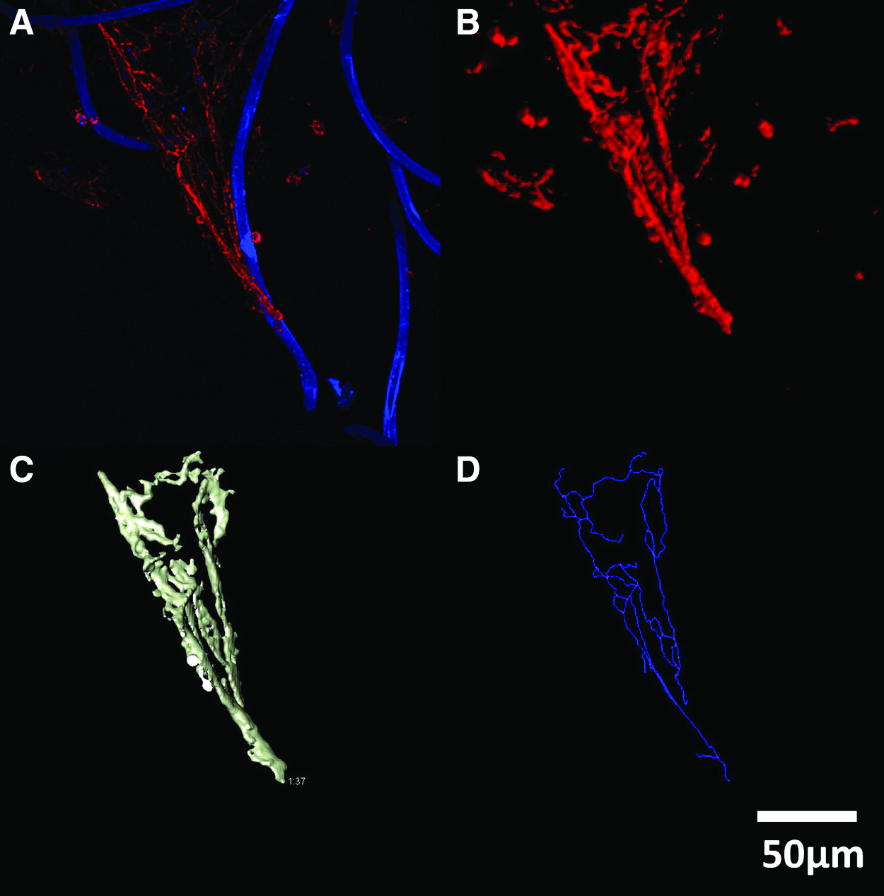
Schematic two-photon laser scanning microscope (TPLSM) data processing for quantification of capillary-like structures;
Statistical analysis
Values are expressed as the mean±standard error of the mean. For TPLSM, the datasets were obtained with three different HUVEC primary cell donors (n=3 wells per condition). The same supportive primary cell donor was used for all experiments. A multiple comparison one-way ANOVA with subsequent Bonferroni correction was performed for standard deviation errors. Differences were considered to be statistically significant at p<0.05.
Results
Characterization of isolated cells
Supportive HFFs as well as HUVECs were characterized by staining for alpha-SMA and PECAM-1, respectively, to determine their purity. HFFs were stained negatively for PECAM-1. HUVECs were stained positively for PECAM-1 and alpha-SMA staining was absent (see Fig. 1).
Cytotoxicity and proliferation assay
The cytotoxicity of the non- and RGD-functionalized PLLA material on HFFs and HUVECs was evaluated with regard to LDH release. The exposure of cells to the PLLA contact medium for 2, 4, 6, and 9 days showed no significant difference in AK release compared with the untreated controls (negative controls) for both cell populations. Therefore, neither the nonfunctionalized PLLA nor the RGD-functionalized PLLA elicited cytotoxic effects (Fig. 4A, B). The effect of non- and RGD-functionalized PLLA on the proliferation of HFFs or HUVECs was assessed using the XTT assay after 2, 4, and 6 days. For both cell types, the nonfunctionalized PLLA contact medium did not cause any significant change in the proliferation of the cells compared with the untreated controls (negative controls). A similar result was observed for the RGD-functionalized PLLA (Fig. 4C, D).
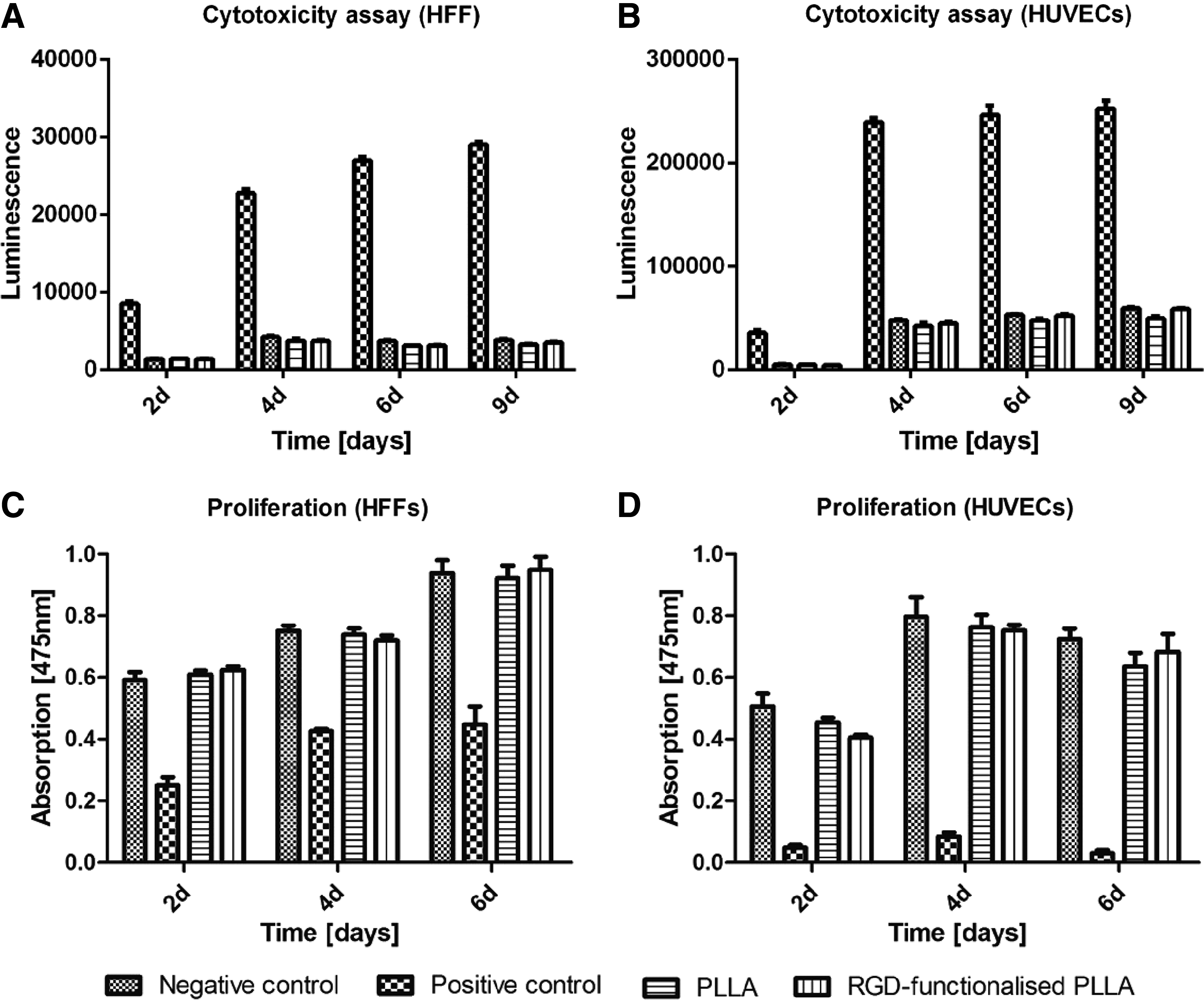
Cytotoxicity assays of non- and RGD-functionalized PLLA on
Coculture assay
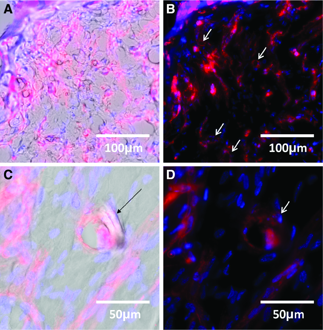
Fluorescence imaging and TPLSM demonstrated that the HFF/HUVEC cocultures employed in the study developed capillary-like structures in 2D and 3D (Fig. 5A, B). Additionally, the formation of the capillary-like structures adjacent to both the RGD-functionalized and nonfunctionalized PLLA fibers was possible (Figs. 6A, B and 8C). The capillary-like structures adjacent to RGD-functionalized PLLA fibers persisted after 21 days (Fig. 5D).
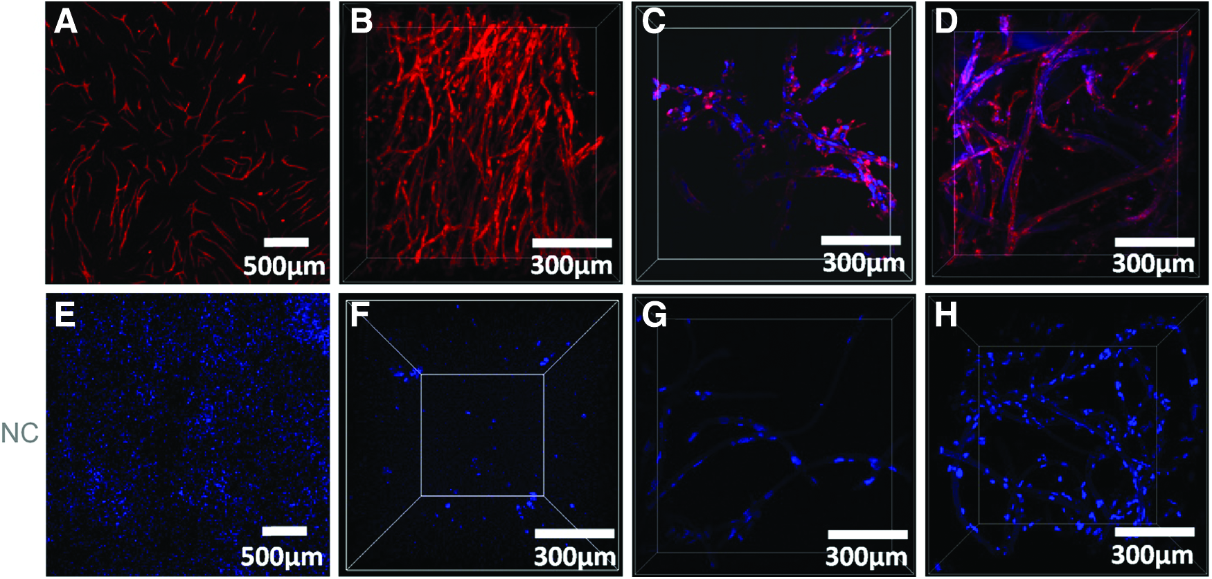
Staining of HUVECs or HFF/HUVEC coculture;
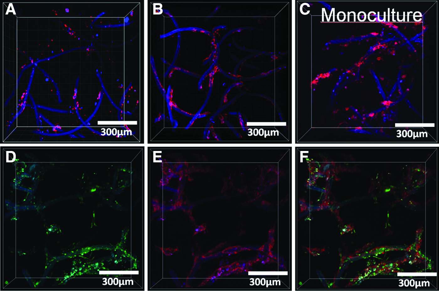
HFF/HUVEC coculture or HUVEC monoculture adjacent to
Biofunctionalized fiber assay
RGD immobilized on the surface of the fibers via an HDI spacer was shown to enhance capillarization in the HFF/HUVEC coculture system adjacent to these fibers compared with the nonfunctionalized fibers (Fig. 6A, B). The HFFs were located adjacent to the HUVECs on the biofunctionalized microfibers (Figs. 6D–F and 8A, B). The HUVEC-only culture adjacent to biofunctionalized microfibers demonstrated no capillary-like structure formation (Fig. 6C). HFFs adjacent to the microfibers also orientated adjacent to the fibers, but in addition, migrate into the surrounding fibrin gel (Fig. 6D). The quantification of microvessel characteristics showed that the total MVL, fVV, and BI increase in the vicinity of RGD-functionalized fibers compared with nonfunctionalized control fibers (Fig. 7). This could be shown for three different donors. Regarding the mean total length values for the capillary-like structures next to the microfibers, there was a significant increase from 9.68×10⁻⁹±2.25×10⁻⁹ μm2 in the nonfunctionalized group to 1.74×10⁻⁸±2.93×10⁻⁹ μm2 in the RGD-functionalized group.
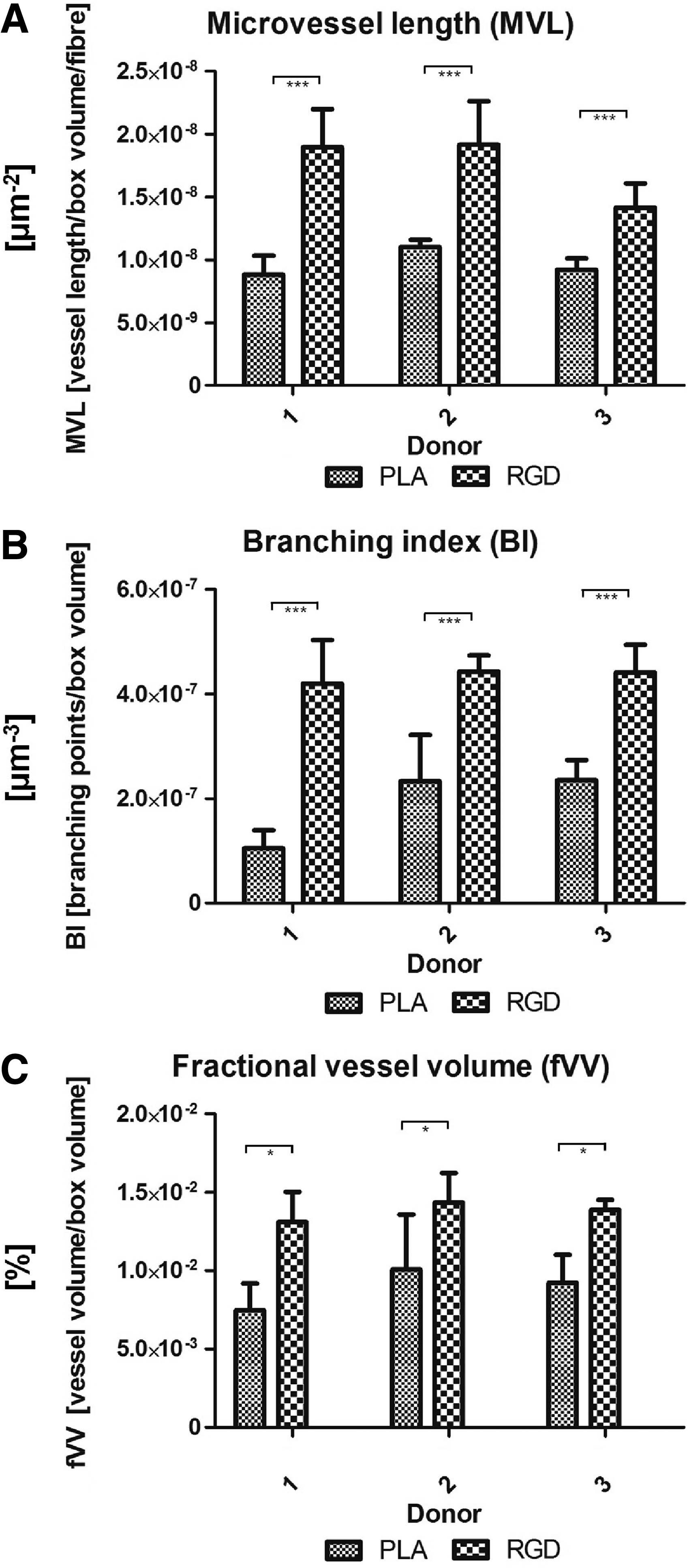
Quantification for all three donors of capillary-like structures next to non- and RGD-functionalized microfibers;
For volume measurements, the mean fVV adjacent to nonfunctionalized microfibers was significantly augmented from 8.18×10⁻³±3.93×10⁻³% to 1.38×10⁻²±1.56×10⁻³% adjacent to RGD-functionalized microfibers.
With respect to mean values for branching of the obtained capillary-like structures, the mean BI was significantly increased from 4.42×10⁻⁷±5.52×10⁻⁸ μm3 in the RGD-functionalized group compared with 1.92×10⁻⁷±4.93×10⁻⁸ μm3 in the nonfunctionalized group.
Using TPLSM, lumen formation after 9 days in a coculture system could also be visualized. Optical sections at various depths in the tube (Fig. 8a, b) demonstrate the presence of such lumen. Image reconstruction using Imaris 7.4 software (Fig. 8c) confirms this. Also, cryosections (Fig. 9) demonstrate lumen formation. Additionally, two side branches are visible in the 3D reconstruction (Fig. 8c).
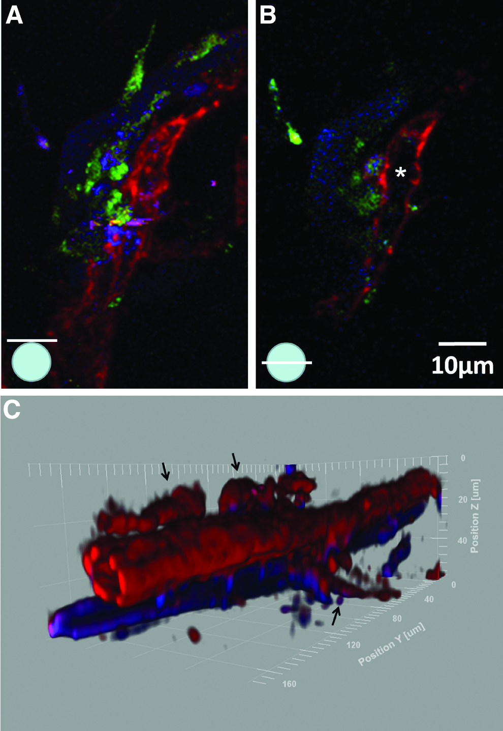
Optical section of capillary-like structures after 9 days next to biofunctionalized microfibers indicating a lumen formation; optical section
Cryosections of HFF and HUVEC cocultures in a fibrin gel after 9 days; lumen formation is visible in the
Discussion
Several groups are pursuing different strategies to vascularize tissue-engineered organs with the aid of coculture systems, including the application of bead assays, sheets, spheroids of coculture, or scaffold-supportive approaches.2,5–7,22 All of the aforementioned strategies are based on the creation of a 3D prevascularized network within a scaffold that can be transplanted in vivo, although the directional control of this network formation is not normally taken into consideration. The engineered in vitro vessels are typically randomly distributed within the construct, making it difficult to reform, for example, the vasculatures' architecture in an organ such as the liver. To ensure that a tissue-engineered vessel network infiltrates the entire construct, one requirement would be an even distribution of the vessel-forming cells inside the proposed structure. However, although the cells may be evenly distributed, the connection that is formed with neighboring cells is entirely random, resulting in an unstructured network with unknown connection points. It is therefore essential that the direction of vessel growth is considered in prevascularization of structures in vitro.
With respect to angiogenesis in humans, different growth factors and ECM molecules guide and progress the patterning of newly formed branches. 23 This vascular patterning is specific for every organ and only partially understood on a molecular level. With these guiding molecules, blood vessel development in every tissue is strictly controlled with regard to the positioning and distance of the newly formed vessels from other cells, and also from neighboring vessels. Further, since a rapid connection of the host vessel system with that of the tissue-engineered construct is required, an appropriate connection point needs to be provided within the tissue-engineered construct. If a connection and a directional development of blood vessels can be ensured within a 3D matrix, then adequate supply of all seeded cells in close proximity to vessels (100–200 μm) can be ensured. In this regard, textile spacer fabrics, for example, with a distance of 100–200 μm, can help to orientate vessels in a 3D fibrin matrix, ensuring appropriate configuration of the vascular microarchitecture within this tissue-engineered construct.
In the present study, we have shown that 10-μm-thick biofunctionalized nonwoven PLLA microfibers can orientate HUVECs to form directed capillary-like structures in an HFF/HUVEC coculture system within a fibrin gel.
For this purpose, it was necessary to evaluate whether non- or biofunctionalized PLLA had any influence on the supportive or vessel-forming cells employed. In all cases, the materials were neither cytotoxic, nor had an influence on proliferation of the cells. With respect to the literature, PLLA has previously been observed to have no negative proliferative effect on keratinocytes or dermal fibroblasts. 24 Additionally, HDI as a spacer used in this study is also known to be a nontoxic coupling agent. 25
The fiber material employed in the study, PLLA, degrades over time as described in the literature after ∼9 months, 26 and should be exchanged by vessel-supportive ECM produced primarily by the supportive fibroblasts. 27
With regard to the directed development of capillary-like structures, the orientation of vessel-forming HUVECs has been demonstrated by Sukmana and Vermette 28 and Hadjizadeh and Doillon 11 by using stretched 100-μm-thick biofunctionalized polyethylene terephtalate monofilaments orientated in parallel in a fibrin gel. These parallel-orientated fibers are used to form capillary-like structures either in between the fibers 28 or adjacent to them. 11 The orientation of the fibers used in the present study allowed a more expansive orientation of the capillary-like networks with respect to 3D within the fibrin matrix, although they were directed along the fibers. The primary cells used in coculture were tested previously for their vessel-forming ability by 2D and 3D angiogenesis assays. Such tests are necessary as it is known that not all primary cells from different donors perform in the same manner together to support and develop vessels. In this assay, we demonstrated that the proposed cells form capillary-like structures in 2D and 3D (Fig. 5).
Lumen could be demonstrated in the 3D coculture system adjacent to biofunctionalized microfibers, but do not form throughout the entire endothelial network (Figs. 8 and 9). Using cocultures of HFFs and HUVECs, several groups have demonstrated lumen formation, even after 10 days of culture.12,29,30 Additionally, they have shown that a connection of the preformed network to the host vasculature using a coculture system of fibroblasts and HUVECs is possible after transplantation in vivo. 5 After 9 days, we could observe the initial signs of luminal development. Regarding the proximity of vessel-forming endothelial cells to supportive HFFs (Fig. 8), it was observed that HFFs were close to endothelial cells supporting the lumen formation. 30 It could be that HUVECs wrap around the orienting PLLA and the lumen is occupied by the material, although we have not seen this in the supportive surrounding fibrin gel matrix.
Another important reason to use a coculture is the ECM since it is essential for all stages of angiogenesis. 31 The ECM is a dynamic and bioactive structure that influences cells using both mechanical and chemical signals. 8 In a coculture system with fibroblasts in a fibrin gel, it could be demonstrated that the components secreted by the supportive fibroblasts all had an influence on the ECM supporting lumen formation. 9 It is suggested that the ECM stiffness is increased by the secreted proteins. With respect to this issue, it could be shown that endothelial contractility seems to be influenced by ECM density in fibrin gels, resulting in less capillary-like structures in the proposed coculture system. 32
By comparing RGD-functionalized with nonfunctionalized PLLA microfibers, we observed that more capillary-like structures could be obtained adjacent to the RGD-coupled fibers. This can be explained by the process of cell seeding, during which RGD present on the fibers improved cell attachment, and subsequently supported the formation of more structures adjacent to the fibers. The immobilized GRGDS coupled to an HDI spacer in this study is a fibronectin sequence that has previously been used to improve HUVEC33,34 or HFF35,36 adhesion compared to nonmodified materials. However, in the previously mentioned fiber assay of Hadjizadeh and Doillon, 11 RGD immobilization showed no significant improvement of capillary-like structure formation, although a tendency is visible. Despite the fact that the RGD sequence with the same amino acids (GRGDS) was immobilized in this study, a difference lies in the additional HDI spacer in our study. It has been shown that the use of GRGDS linked to a polyethylene glycol (PEG) spacer arm further improved the attachment of HFFs in PEG hydrogel compared with the RGD control without a spacer arm. 35 The spacer arm could therefore play an essential role for improved attachment of the seeded cells. Regarding the modified PLLA material, it could be shown that MCR5 fibroblast attachment improved for RGD-grafted PLLA films compared with coated PLLA. 37 Another group demonstrated the positive effect of poly-L-lysine-coupled RGD adsorbed to PLLA, leading to enhanced bovine aortic endothelial cell attachment. 34
If HUVECs alone are seeded onto the biofunctionalized fibers, they attach to the fibers, but do not form capillary-like networks with lumen. With regards to the literature, a monoculture of HUVECs on beads within fibrin gel also resulted in no capillary-like structure formation. 38 Since only the HFF/HUVEC coculture resulted in more capillary-like structures adjacent to RGD-biofunctionalized fibers compared with nonfunctionalized microfibers, a cooperative effect of both biofunctionalized microfibers and HFFs can be determined.
It is known that fibroblasts secrete several factors like, for example, VEGF or bFGF that have an influence on angiogenesis.5,8,9 The direct contact of fibroblasts to endothelial cells is not necessary to obtain luminal structures,5,9,11 although the fibroblasts help to stabilize and support maturation of the developing vessel network. 30 In this study, we have not specifically demonstrated a positive stabilizing effect of the fibroblasts on the network, but we demonstrate that the fibroblasts are positioned adjacent to the capillary-like structures, which may promote network development and support.
For a directional development of capillary-like structures, it has been shown that the positioning of cells adjacent to the fibers guides the development of the capillary-like structures along the PLLA fiber axis. Guided directional development of vessel structures has been attempted using several structures and culture conditions, including fibers,11,28 porous or channeled framework structures,22,39–43 and flow. 44 In all of these approaches, excluding flow, cellular orientation has been successfully guided. It appears that if the guiding material leads along a 1D axis and is not crossed by another guiding structure, then the vessel also orientates in one direction. This can be observed primarily in fiber11,12 and channel approaches 41 in addition to the findings of the present study. It seems as if the biofunctionalized fiber helps the endothelial cells orientate to form a capillary-like structure, although the exact mechanism of capillary guidance remains unknown.
With regards to the possible integration of the preformed networks demonstrated here with the host vasculature, it has previously been shown that a connection of in vitro-generated networks to the host vessels is possible using a fibrin matrix cocultured with fibroblasts and endothelial cells. 5 The potential for our system to integrate with the host vasculature will be tested in the future by performing an in vivo study.
Conclusions
The present study has demonstrated that directed vascularization in a HUVEC/HFF coculture system can be realized by using RGD-biofunctionalized PLLA microfibers (10-μm diameter) as a guidance system. The formation of capillary-like structures adjacent to the biofunctionalized fibers was shown to be possible only if HFFs are present as support cells in the culture system.
Compared to previous studies using fiber guidance, the microfibers employed here are thinner and therefore more suitable to orient blood vessels in a 3D scaffold. Further, we have shown that vascularization is ameliorated by RGD-biofunctionalized PLLA microfibers due to enhanced binding of HUVECs compared with nonfunctionalized microfibers. Future studies include the controlled arrangement of the microfibers in a distance of 100–200 μm for a directed blood vessel development in 3D tissues. Further, the investigation of other endothelial cell types such as microvascular endothelial cells would be of significant interest to determine and prove a more general beneficial effect of this system.
In addition, an in vivo study needs to be performed to determine the functionality of the resulting network.
Footnotes
Acknowledgments
This work was supported by the two-photon image facility, a core facility of the Interdisciplinary Center for Clinical Research (IZKF) Aachen within the Faculty of Medicine at RWTH Aachen University, Germany. Further, funding was provided by Deutsche Forschungsgemeinschaft (DFG) graduate school BioInterface 1035.
The authors thank Kim Douma from the Department of Biomedical Engineering at Maastricht University Medical Centre in the Netherlands for his support in 3D quantifications.
Disclosure Statement
No competing financial interests exist.