
Abstract
Modern industrial and medical applications require soft actuators with practical actuation methods, capable of precision control and high-speed performance. Within the realm of medical robotics, precision and speed imply less complications and reduced operational times. Soft fluidic actuators (SFAs) are promising candidates to replace the current rigid endoscopes due to their mechanical compliance, which offers safer human–robot interaction. However, the most common techniques used to operate SFAs, pneumatics, and hydraulics present limitations that affect their performance. To reduce manufacturing complexity, enhance response time, improve control precision, and augment the usability of SFAs, we propose a Pneudraulic Actuation (PHA) system that, for the first time, combines a pneumatic and hydraulic circuit in series. To examine this proposal, a comparative assessment of the proposed actuation technique with the common techniques was carried out, in terms of bending performance and generation of audible noise level during functioning. The analysis provides insights into the performance of various fluidic actuation methods for SFAs, highlighting significant effects related to fluid–structure interactions and the presence of trapped air. Thereafter, a comparative assessment of different fluidic circuits is performed, illustrating how tubing length, inner and outer diameter, as well as the amount of different fluidic medium impact the dynamic behavior of the system, amplifying the importance of fluid mechanics for design optimization. Furthermore, we propose a model-based control strategy that solely focuses on fluid dynamics, utilizing the hydraulic-electric analogy and the resistor–inductor–capacitor circuit theory. Our PID controller improved actuation speed by 52.63% and reduced audible noise by 17.17%.
Introduction
Soft robotics are making a positive impact in fields such as health care, agriculture, and industry due to their ability to safely handle delicate objects and morph around complex shapes.1,2 They also provide cost-effective alternatives to rigid robots. 3 To improve the precision, response, and usability of soft robots and to reduce complexity and maximize effectiveness, enhancing actuation performance is essential.4,5
Actuation of soft robots is achieved by various methods, including tendons, shape memory alloys, and fluids.6,7 However, soft fluidic actuators (SFAs), which consist of soft bodies with inflatable cavities and deform upon fluid injection, represent over 75% of these methods. 8 This is due to its straightforward fabrication process and its high passive compliance and deformability 9 —qualities that are particularly advantageous for medical applications. 10 Moreover, compatibility with lithographic processing makes them suitable for applications even at microscale. 11 Pneumatic soft actuators are the plurality 12 ; however, hydraulic soft actuators are becoming increasingly popular for their enhanced actuation performance and efficiency. 13
The performance of SFAs is coupled with the design of their inflatable cavities and the actuation strategy. Pneumatic systems rely on creating a controllable pressure difference between the source and the cavities. While different energy sources exist, 14 pneumatic circuits frequently consist of an air compressor paired with pressure regulators and solenoid valves. 15 Pneumatics offer fast pressure generation with low mechanical and fluid friction, 16 enabling actuation speed to scale with pressure. This approach is practical and cost-effective, 17 ensuring that SFA’s compliance remains unaffected by the actuation fluid. 18 Additionally, compressed air is readily available in operating rooms, making pneumatics an ideal choice for medical applications. Albeit there are drawbacks, like limited force output and challenges in precise control due to the nonlinear behavior of elastomers and air compressibility, which requires adequate modeling. 19 In contrast, hydraulic circuits offer higher actuation efficiency by using an incompressible fluid and typically regulate the amount of fluid infused or withdrawn from cavities through volume control. Multiple types of liquid-based pumps exist such as rotary diaphragm, 20 centrifugal, 21 and peristaltic, 22 but syringe pumps are favored, 23 for their model-based ability to control the fluid’s flow rate and volume. 24 Volume control can be deemed preferable for configuration control in soft robotics, as the relationship between volume, elongation, and motion is more direct, leading to greater precision and safety.25,26 Nonetheless, hydraulics can affect the SFA’s mechanical compliance and may reduce response time, compared to pneumatics, due to greater mechanical and fluidic friction. Consequently, hybrid systems were developed to harness the strengths of different actuation methods.
A robotic arm was controlled using an air-hydraulic servo booster to increase payload and enable compliance and precision control in aquatic environments. 27 This complex system includes multiple pneumatic solenoid valves that activate separate hydraulic pistons antagonistically. Dynamic control focuses on mechanical and fluidic models of the pistons, arm, and fluidic flow within the booster’s orifice. However, fluid dynamics within the tubing are ignored. Additionally, a motor was powered by pressurized liquid, as compressing liquid rather than gas improves actuation efficiency. 28 In the same vein, various actuation techniques have been fused with soft robots (Summarized in Table 2 of Pagoli et al. 29 ) to improve aspects such as performance, stiffness, and workspace. Given the dominance of fluidic actuation, we focus on hybrid fluidic systems.
A hybrid actuation method using two syringe pumps operating in parallel, one with water and one with air, was introduced to modulate the stiffness and force output of a SFA. 30 Such systems are complex and expensive to manufacture, as multiple syringe pumps are required. 31 Although hybrid systems with a single syringe pump can simplify manufacturing, 32 viscous friction in the tubing and stiction and Coulomb friction from the O-ring seal 33 act on the syringe plunger. Accordingly, to increase response times, the motors must either be powerful and therefore bulky or be equipped with a high gear-ratio gearbox, which would significantly reduce the speed of the lead screw system. Recently, a hybrid system that omits the use of a syringe pump was suggested for amphibious applications. 34 The system relies on multiple diaphragm pumps and utilizes a representation-based learning controller on a three-port solenoid valve for pressure control. Diaphragm pumps can introduce pulsating flow requiring an air chamber (dumper) and have moving parts, generating noise and demanding periodic replacement. 35 Ultimately, the proposal of the study increases hardware requirements without providing insights into the factors influencing performance.
To analyze SFA’s performance and enhance dynamic controllability, fluid–structure interaction 36 and fluid mechanics 37 should be examined, as fluid energy distribution is neither immediate nor uniform due to fluid properties and viscous losses. 38 Pressure variations in air-filled cavities have been shown to cause localized stress concentrations and uneven deformations, 39 especially at high pressurization rates. 40 This, coupled with the inherent characteristics of the elastomer—including nonlinearity and hysteresis 41 —complicates their control when using a generally preferred model-based approach, 42 which can require finite element analysis. 43 So far, the Lagrangian 44 or Cosserat Rod-Base 45 method has been primarily used to model SFA’s mechanical dynamics, neglecting fluid dynamics. 46 The trend toward smaller SFAs,47–49 however, will inevitably increase the importance of fluid dynamics over solid mechanics. Accurately predicting 3D fluid flow requires solving computationally expensive differential equations (Navier–Stokes). To simplify this, prior studies have applied the hydraulic-electric analogy to derive governing differential equations for fluid flow in microfluidic chips50–52 and the cardiovascular system.53,54
In this article, we introduce a pneudraulic actuation (PHA) method and apply it to SFAs for the first time. This setup allows us to study the effects of fluid compressibility within elastic cavities and effectively model system dynamics using solely fluidic models. The main contributions of our study are:
A unique PHA setup for SFAs that combines pneumatic and hydraulic circuits in series with a proportional pressure regulator, reducing hardware complexity and audible noise. A comparison of fluidic elements influencing dynamic behavior, supporting design optimization of similar actuation systems. A model-based controller that focuses solely on fluid dynamics, utilizing the hydraulic-electric analogy and resistor–inductor–capacitor (RLC) theory. The proposed setup and controller improves precision and actuation speed (by 52.60%).
Materials and Methods
Pneudraulic actuation method
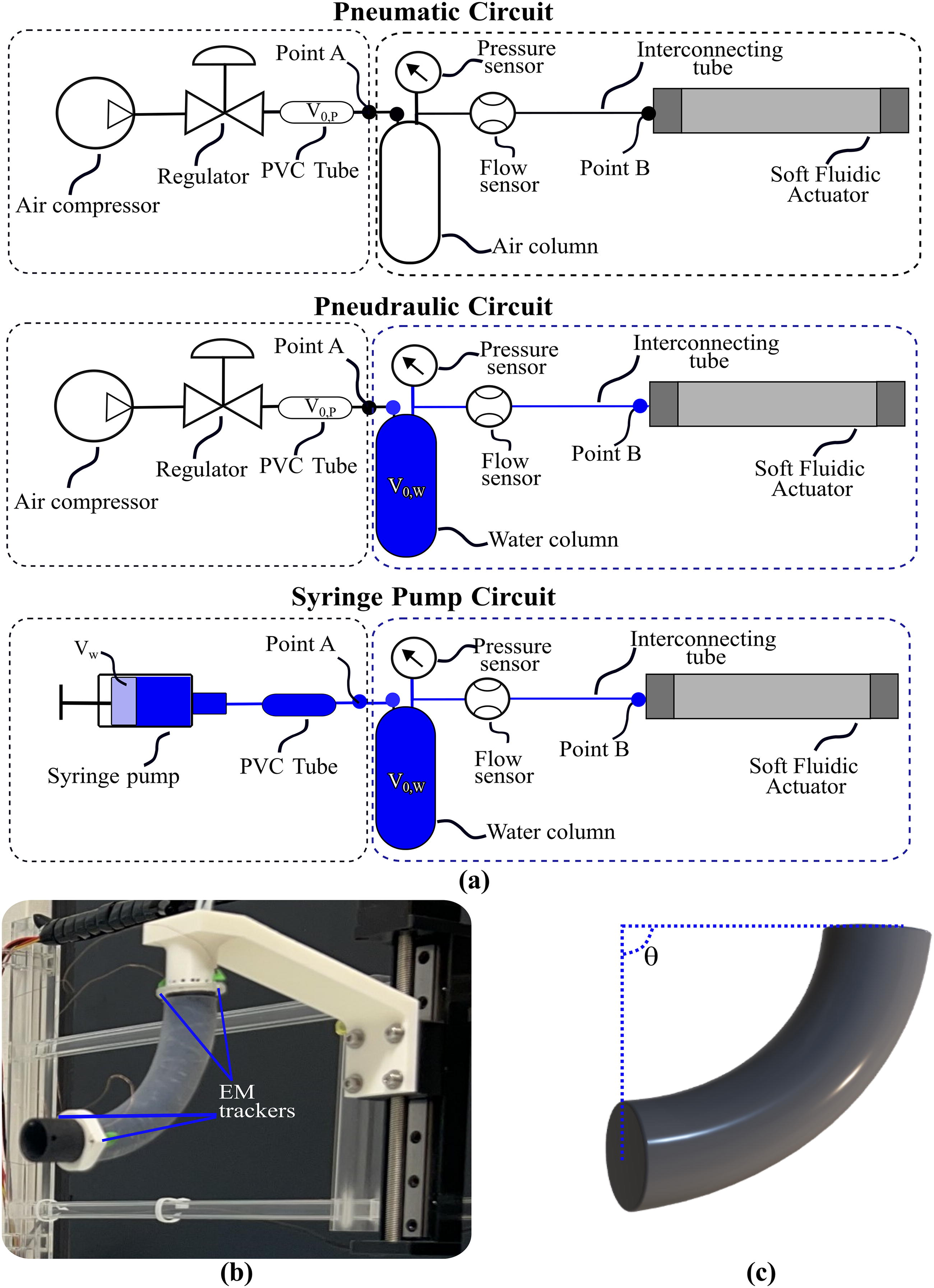
The PHA has three identical channels (Fig. 1a). A single channel consists of a pneumatic- and hydraulic-analogue circuit connected in series and separated at Point A (Fig. 1c). Anything before Point A is called the “actuation circuit,” and thereafter, the “fluidic circuit.” The “actuation circuit” consists of an air compressor and an electronic proportional pressure regulator (Series K8P, Camozzi Automation). Hard polyvinyl chloride (PVC) tube with

Elements of the pneudraulic actuation (PHA).
Soft fluidic actuator
The SFA employed in this study (Fig. 1b) is part of the self-propelled MorphGI endoscope. 55 Its body is made from Shore A-20 silicone (RTV4420 Silbione) and measures 70 mm in length with a diameter of 17.5 mm. It features seven cavities: three for actuation and four working channels. The actuation cavities are cylindrical, with an inner diameter of 2 mm and an outer diameter of 6.5 mm. The outer diameter is defined by the polyethylene terephthalate (PET) woven mesh, which limits expansion and promotes bending and the reinforcement spring in the working channels to prevent radial collapse.
Fundamentals of hydraulic-electric analogy
Electric and fluidic circuits exhibit analogies defined by Hagen–Poiseuille law. Table 1 lists key microfluidic parameters and corresponding electronic components for assembling microfluidic circuits, from which the electric equivalent of a single actuation channel of PHA is composed (Fig. 2).

Hydraulic-electric analogy representation. The figure depicts the symbolic equivalent of fluidic components with the electric equivalent. Specifically,
Microfluidic and Electronic Components Analogy from Hagen–Poiseuille’s Law [Units]
The linear and proportional relationship between pressure difference (
The
Circular elastic tubes can be approximated as thick-wall pressure vessels, whose fluidic capacitance (
Fundamental of RLC circuit theory
The three main circuit components, besides the voltage source, are the resistor (R), inductor (L), and capacitor (C). The equations following derivations are obtained online.
57
Using Kirchhoff’s voltage law, the differential equation between the voltage of the source,
The characteristic equation in the Laplace domain of the serial RLC circuit is as follows:
The roots of (8) can be expressed as follows:
There are three possible time domain behaviors of voltage,
Experiments
The bending performance of a single actuation cavity is analyzed based on the symmetrical cross-sectional area of the SFA. The experiments conducted are summarized below, with notations indicated in Figures 1 and 2.
Summary of the Control Variables Used for the Different “Fluidic Circuits” of the Four Sub-Experiments of Experiment 2
Finally,
Results
Experiment 1
Figure 3 illustrates the symbolic representation of the three actuation circuits and the experimental setup, while Figure 4a and b presents the results from the different repetitions alongside an empirical quadratic function. The segment shows good repeatability in terms of bending. The pressure regulator stabilizes the SFA at each actuation interval, whereas a syringe pump causes an exponential decay in the bending angle due to viscoelastic relaxation (Supplementary Data S1). The average root-mean-square error (RMSE) from each distinct repetition against the average of all repetitions is 0.61°, 1.89°, and 2.03° for the PHA, pneumatic, and syringe pump, respectively, and 2.80° for the model. Using an incompressible fluid, the segment reaches ≃132° at 6 bar. Examining Figure 4b, there is an interesting observation. When the actuation medium is incompressible and
“Actuation circuits” comparative assessment.

Results of Experiment 1.
Experiment 2
Sub-experiment 1 focused on investigating the impacts of
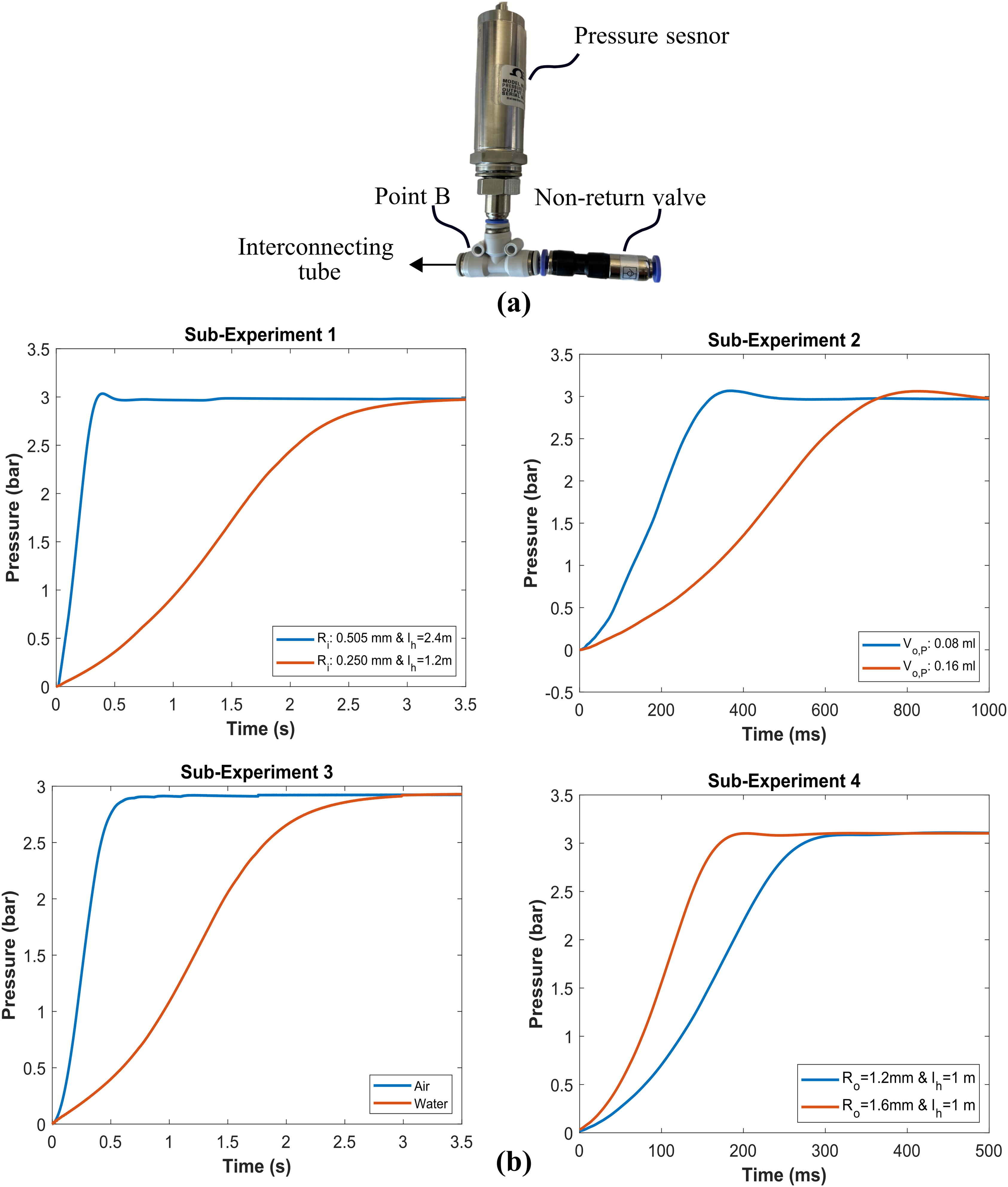
Results of sub-experiments from Experiment 2.
Experiment 3
The
Tolerance and fabrication imperfections (Fig. 6a) suggest that

Results of Experiment 3.
However, postactuation water is displaced from the water column (Fig. 6b), which causes a discrepancy in the
Figure 6c shows experimental and predicted pressure curves using the RLC model (
Experiment 4
The control strategy of our PID loop is visualized in Figure 7a. In a real-life application, the pressure sensor used at Point B for feedback will not be present. Thus, depending on the desired pressure (

Results of Experiment 4.
Discussion
Actuation circuit
To our knowledge, this is the first comparative assessment of actuation methods with a focus on fluid–structure interactions and audible noise. Enhanced workspace with an incompressible fluid and stiff segment likely relates to the fluid’s bulk modulus (β). β, the ratio of dP to relative volume change (ΔV/V), is
Pneumatic and PHA systems provide consistent bending due to regulated pressure, unlike syringe pumps, which depend on volume control and are affected by trapped air. 65 This variability causes differences in bending angle for the same injected volume. Additionally, the exponential decay in bending angle results from the viscoelastic relaxation of silicone, 66 as syringe pumps are inactive postactuation. Conversely, the pressure regulator, being constantly energized, can maintain a constant bending angle. A normally open solenoid valve could help our PHA maintain system pressure and enable intrinsic force sensing using the hydraulic fluid. 67 Finally, a hydrophobic membrane improves viability and safety by retaining water without relying solely on gravity.
Research shows that noise levels in operating rooms (OR), which can range from 51 to 79 dB, negatively impact surgical team performance.
68
The maximum noise using a pressure regulator during actuation and deflation is 80 and 105 dB, respectively. Although the deflation noise is high, it could be managed by using a pneumatic exhaust and placing the regulator within a soundproof enclosure. This highlights the need to consider aeroacoustics
69
or electric motor noise
70
in future medical actuation mechanisms. Pneumatic devices release compressed air in high-speed jets, allowing the noise level near the source to be calculated as follows (assuming adiabatic conditions):
Bending speed is affected by the dynamic response of any syringe pump and its ability to overcome mechanical and fluidic friction. This depends on the choice of the DC motor and the design of the lead screw system. The torque
Summary of Key Performance Observations from Experiments 1 and 2 and Literature on Different Fluidic Actuation Methods
Compressed air is readily available in operating rooms.
Scales with pressure difference.
Depends on motor design and power.
Selectable pressure levels prevent issues with viscoelastic relaxation and trapped air in fluid lines.
SFA, soft fluidic actuator.
Fluidic circuit
Comparing τ from Experiment 2 highlights the importance of fluid mechanics in microscale actuators. As shown in Fig. 5a, a 50% reduction in interconnecting tube’s
Results from Experiment 3 indicate that the hydraulic-electric analogy and the RLC approximation can effectively predict transient pressure behavior. Nonetheless, inaccuracies ascribed to material nonlinearity, hysteresis, and geometric nonuniformities of the device can affect its accuracy. 50
Enhancement of bending speed
The result of Experiment 4, which implemented a PID controller using a regulator and air compressor with a broader operating range (0–7 bar) than that of the system (0–6 bar), showed that response times (or bending speed) can be improved by 52.6% if there is “excess” supply pressure. This should not create a problem, as compressed air (>13.79 bar) is present in OR to operate pneumatic surgical instruments.
72
Such control approach suits SFAs with predefined motions, like self-propelling soft endoscopes.
73
Potentially though, excessive pressure may cause the SFA to fail. Additionally, since only positive pressure inputs can be applied by the regulator, relaxation speeds cannot be enhanced. The dynamic nature of
For our SFA, dynamics of mechanics slightly dominate the bending response and should be considered in the future. 76 The open-loop time constant of bending from Experiment 4 is 0.53 s. However, based on the results from Experiment 3, it should be 0.48 s. Although small, this dominance is expected to diminish as SFA gets smaller and requires less volume for actuation, an element which will also increase the rate of actuation. 40
Conclusion
Our proof-of-concept and setup characterization of the PHA contributes to advancing SFAs usability and enhancing controllability. Comparing three actuation setups shows that stiff segments at high pressures achieve better bending performance with an incompressible fluid, likely due to factors related to fluid–structure interaction. PHA is simple to manufacture and can maintain a stable bending angle, compared to syringe pumps. It also offers greater consistency and is quieter during operation compared to a pneumatic pump. Key design choices impacting PHA response time include: the air and water volume in the “actuation circuit,” the smallest inner radius of the tubes in the “fluidic circuit” and the flexibility of the actuation cavities. Using the hydraulic-electric analogy and RLC circuit theory, we developed a model-based PID controller, which can improve bending speed by 52.63%.
Footnotes
Authors’ Contributions
D.M.: Conceptualization, methodology, software, formal analysis, investigation, data curation, writing—original draft, and visualization. S.W.: Methodology, investigation, and resources. W.H.: Investigation and resources. L.L.: Conceptualization, writing—review and editing, and supervision. W.X.: Writing—review and editing and supervision. H.L.: Conceptualization, writing—review and editing, supervision, project administration, and funding acquisition.
Author Disclosure Statement
No competing financial interests exist.
Funding Information
This research is funded by an internal King’s College London (KCL) grant from CDT in Surgical & Interventional Engineering and the InnoHK program.
References
Supplementary Material
Please find the following supplemental material available below.
For Open Access articles published under a Creative Commons License, all supplemental material carries the same license as the article it is associated with.
For non-Open Access articles published, all supplemental material carries a non-exclusive license, and permission requests for re-use of supplemental material or any part of supplemental material shall be sent directly to the copyright owner as specified in the copyright notice associated with the article.