
Abstract
Soft robots have morphological characteristics that make them preferred candidates, over their traditionally rigid counterparts, for executing physical interaction tasks with the environment. Therefore, equipping them with force sensing is essential for ensuring safety, enhancing their controllability, and adding autonomy. At the same time, it is necessary to preserve their inherent flexibility when integrating sensory units. Soft-fluidic actuators (SFAs) with hydraulic actuation address some of the challenges posed by the compressibility of pneumatic actuation while maintaining system compliance. This research further investigates the feasibility of utilizing the incompressible actuation fluid as the means of actuation and of multiaxial sensing. We have developed a hyperelastic model for the actuation pressure, acting as a baseline pressure. Any disparities from the baseline have been mapped to external forces, using the principle of pressure-based fluidic soft sensor. Computed tomography imaging has been used to examine inner deformation and validate the analytically derived actuation-pressure model. The induced stresses within the SFA are examined using COMSOL simulations, contributing to the development of a calibration algorithm, which accounts for geometric and cross-sectional nonlinearities and maps pressure variations with tip forces. Two force types (concentrated and distributed) acting on our SFA under different configurations are examined, using two experimental setups described as “Point Load” and “Distributed Force.” The force sensing algorithm achieves high accuracy with a maximum absolute error of 0.32N for forces with a magnitude of up to 6N.
Introduction
Soft robots made from pliable materials and incorporating flexible mechanisms offer advantages over conventional rigid robots. 1 Their physical attributes enable the safe handling of delicate objects and facilitate tasks requiring physical interaction with complex anatomical systems. For these reasons, soft robots are utilized across various fields, ranging from soft industrial grippers and manipulators2–4 to biomedical devices such as wearables and implantables, 5 tools for minimally invasive surgery, 6 medical tool guidance, 7 and endoscopic applications.8,9 However, to unleash their full potential and enable high-precision controllability, the body of the soft robots must act as sophisticated systems for both actuation and sensing, 10 resembling monolithically integrated synthetic organisms.11,12 Thus, it is necessary to deepen our comprehension from an engineering perspective using analytical modeling.
Among the several actuation techniques used for soft robots, 13 tendons and/or pressure actuation, known as soft fluidic actuators (SFAs), are widely used. 14 The former technique stimulates the robot by controlling the length of the tendons, whereas the latter uses inflatable cavities. An example of a solely tendon-driven robot is described in the work of Kato et al., 15 whereas Tao et al. developed a soft actuator that combines both actuation techniques. 16 Nonetheless, tendon rigidity and friction create difficulties in the control of soft robots, making SFAs pneumatic17,18 or hydraulic,19,20 the most versatile choice, particularly in the field of medicine. 21 One limitation of pneumatics is the compressibility of the actuation fluid, which significantly complicates the development of analytical models and precise control. Consequently, recent designs utilizing hydraulic actuation leverage the morphological advantages of soft robots, 22 without being impeded by fluid compressibility.
The endeavor to overcome the lack of force feedback by artificially replicating it poses a substantial engineering hurdle requiring multimodal sensory systems. 23 The present cutting-edge tactile sensing technology relies on five distinct sensing principles as follows: resistive, piezoresistive, optical, inductive, and capacitive. 24 The sensing mechanisms can either surround the body of the soft robot, smart skin, 25 and flexible electrodes, 26 or be embedded within structural cavities, conductive liquids, 27 or hydrogels. 28 However, it is undesirable to integrate many rigid sensors in soft robots, because of the manufacturing challenges in miniaturizing electronics 23 and the fear of compromising their ultraflexibility. These challenges led to the development of the pressure-based fluidic soft sensor (PBFSS).
The sensing principle of the PBFSS is to map variations of fluidic pressure against the force stimuli. To date, only a limited number of studies have demonstrated attempts to achieve this, by mostly utilizing pneumatic systems.29–32 While most sensors are used to detect one-dimensional forces, three-dimensional (3D) force sensing is also demonstrated. 33 Because hydraulic sensors respond faster than pneumatics, due to higher stiffness,34,35 we have developed a 3D hydraulic force sensor by coupling three 1-degree-of-freedom (DOF) actuators to form a parallel robot. 36 However, the linear intrinsic force sensing and control method are limited to small motion ranges and rely on empirically calibrated variables for validation. In addition, we have achieved intrinsic force sensing using a stiffness-based nonlinear finite element (FE) model. 37 To account for geometric nonlinearities and to estimate total deflection and orientation changes, the beam was discretized into several serial linkages. Nonetheless, this approach resulted in high-rank matrices that are complex to calibrate. Due to intricate geometric and material nonlinearities, calibration is necessary when using soft robots.38,39 These nonlinearities affect the neutral axis (NA) location, which is crucial for analyzing the kinematic and stress distribution profile.
Assuming quasistatic conditions and small deformations, mechanical modeling 40 proved effective in characterizing the behavior of soft actuators, especially in the bending.41,42 However, hyperelastic models are typically used for actuation pressure, accounting for significant and nonlinear deformations of the silicone body, similar to inflatable balloons.43,44 This study aims to analytically model the biaxial internal deformations and the actuation pressure of unconstrained multichambered SFAs, known as cavity actuators, 45 and the stress distribution under the influence of external force. This will allow intrinsic multiaxial force sensing based on fluidic pressure variations. Although constrained fluidic chambers offer higher actuation consistency, 46 constraining them adds additional manufacturing steps and increases operating pressures even further, affecting structural compliance. The algorithms derived from this investigation are experimentally validated to ensure their accuracy and reliability.
The main contributions of this study to the field of soft robotics are as follows:
Validation, for the first time, of the biaxial deformation of unconstrained fluidic chambers with computed tomography (CT) imaging, allowing the development of an actuation-pressure hyperelastic model. Illustration of the NA shift due to geometric and cross-sectional nonlinearities, improving kinematic modeling. Derivation of an algorithm for intrinsic 3D force sensing, for different force types and configurations, using fluid as both the actuation and sensing medium.
Materials and Methods
The SFA used (Fig. 1) is part of MorphGI,
47
a hydraulically actuated endoscope that uses its tip to anchor and autonomously propel. The main body of the segments has a cylindrical shape of diameter,

Design illustration.
A. Mechanical modeling and stresses
The analysis aligns with the coordinate system depicted in Figure 2. The sensing principle of PBFSS is to map pressure variations (ΔP) of sensory pressure readings

Front segment coordinate system used to derive (1)–(9) and (15)–(24).
Hence, to achieve our objective of utilizing fluid as both the actuation and sensing medium, a
The relationship between stress (
For a curved beam at an angle θ, the stress distribution deviates from linearity and follows a hyperbolic function instead. A force in-line with the bending plane (along
B. NA position
NA is the imaginary line that divides the segmental cross section into two hemispherical sectors. At the NA, stresses and strains are zero (dashed line in Fig. 2). The cross-sectional design and mechanical properties of our segment create a complex variation of NA location, affected by the following three factors: (1) force (or bending) direction (
C. Chamber axial and radial kinematics
Unconstrained chambers experience significant biaxial and nonlinear deformations during actuation. Using conservation of volume, the axial elongation (
D. Actuation-pressure modeling
To develop the baseline pressure
E. Pressure variation and intrinsic force sensing
The analytically derived pressure stiffness
Given the 180° symmetry of the segment:
Expanding and simplifying (18–22) prove that
The parameters CK can be found for a given
More details in Supplementary Data S3.
F. Experiments
FE analysis in COMSOL
56
was performed to visualize the NA shifts. Initially, a constant-magnitude force (0.1 and 2N) of varying direction
To verify the validity of 10 and 14, the SFA was mounted on a linear guide, allowing frictionless elongation. Deionized water, 9.0 mL, was injected inside all three chambers (3.0 mL/chamber) in steps of 1.5 mL, using a syringe pump (PHD Ultra, Harvard Apparatus). At every interval, both during infusion and withdrawal, the pressure and length of the segment were recorded using a pressure sensor (PX190, Omega Inc) and a caliper, respectively. The experiment was repeated three times for three different segments, since the diameter of PET mesh sleeve was optimized from our previous characterization. 47
To evaluate (12), the SFA was placed inside an 8W NanoPET/CT scanner (Mediso Ltd.), while injecting fluidic volume, as described above. Image feedback was captured at each step. To sharpen the distinction between the fluidic chambers and soft material, contrast enhancement (Omnipaque) was used as the sole actuation fluid, since it provides high attenuation of X-rays. 57 A 3D reconstructed model was produced by manual segmentation using a 3D slicer (https://www.slicer.org/).
To verify (15)-(24), two experimental setups were used. To examine multidirectional “point loads,” the SFA was horizontally fixed on a robot arm (MECA500, Mecademic), while calibration weights (0–200 g) were hung from its tip. Due to the compliance of SFAs, even low forces can cause them to deflect, which is why they are generally tested for low-force applications.47,58 After adding each weight, the end-effector was rotated (5°/s) for
In all experiments, we allowed 3 min for viscoelastic effects to diminish before measuring fluidic pressure, since their modeling is beyond the scope of this study.59,60
Results
NA location
Figure 3 displays excerpts from Supplementary Videos S1, S2, S3, S4, showcasing positive bending stresses (
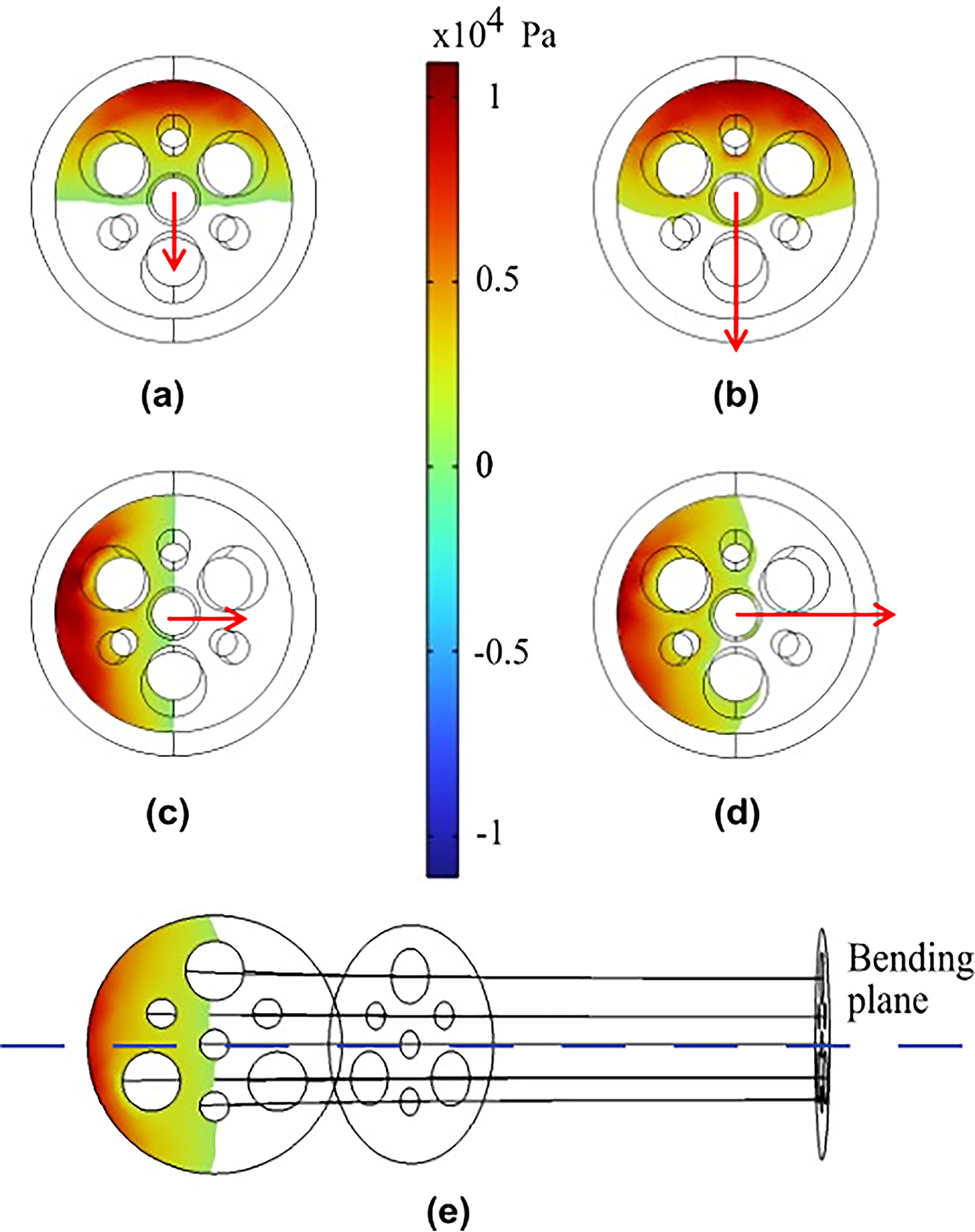
Stress distribution results from COMSOL. Panels
Chamber axial and radial kinematics
The experimental setup, average recorded data across the three segments, and estimated model (10) are shown in Figure 4. Our SFA shows high repeatability. Initially, the rate of
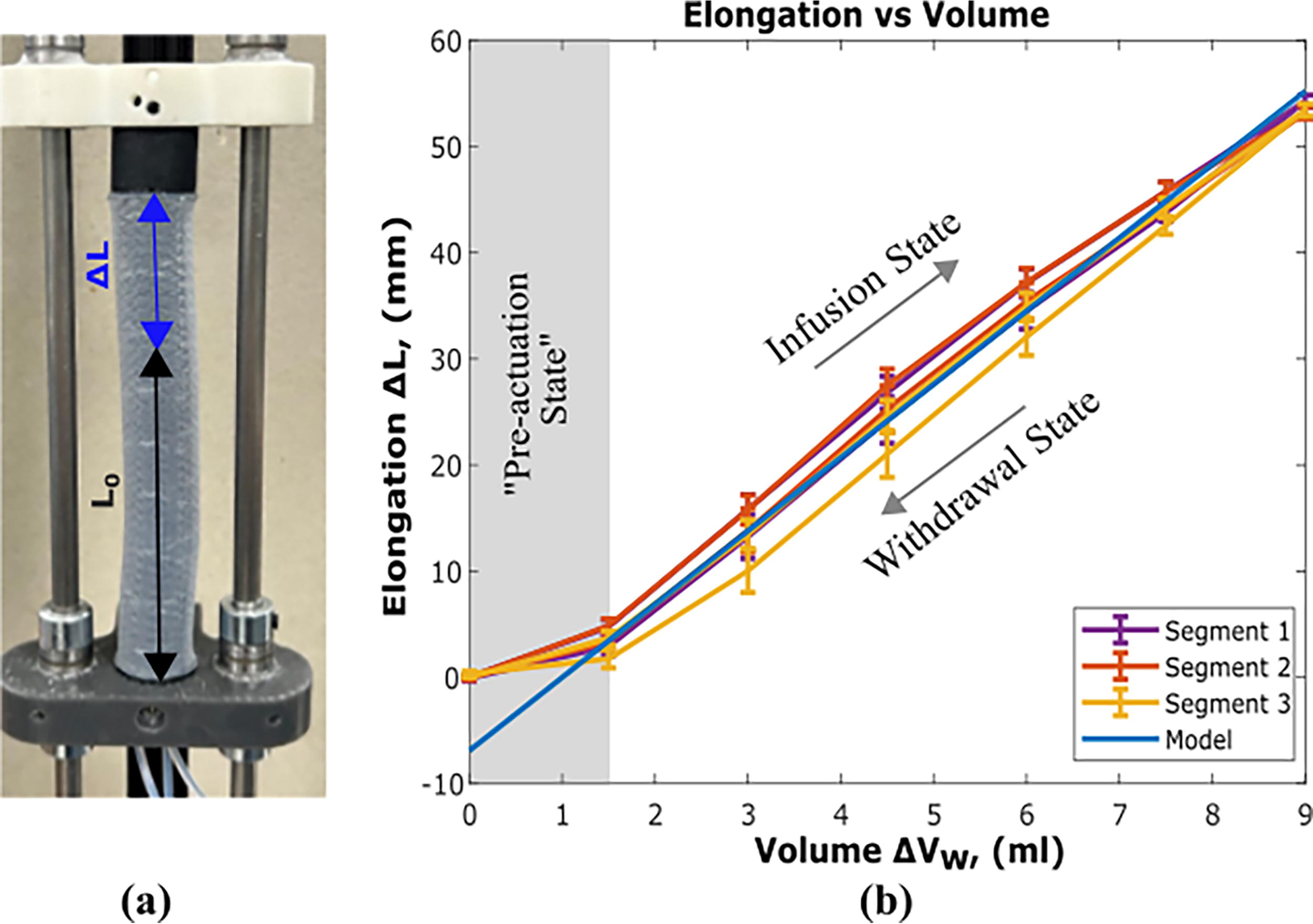
Axial kinematics as derived in (10).
For radial kinematics estimated by (12), the SFA was initially scanned for

Radial kinematics as derived in (12) and results of computed tomography (CT) imaging.

Experimental results with model estimation.
Actuation pressure
The average of the experimental results along with model estimation is depicted in Figure 6b. To account for the expected hysteretic behavior of silicone segments,
61
the material parameters in (14) are selected depending on the infusion/withdrawal state. The model accurately captures the pressure within the Actuation state with an RMSE of 0.12 bar and an MRE of 7.35%. For the maximum injected volume (
Pressure variations under external loading
The experimental setups, configurations, and traced waypoints are shown in Figure 7. For

Experimental setups to examine pressure variation and verify equations (15–24).
Figure 8a-(left) shows the sinusoidal pressure variations in each chamber as the end-effector rotates under a load of 200 g. The MRE of
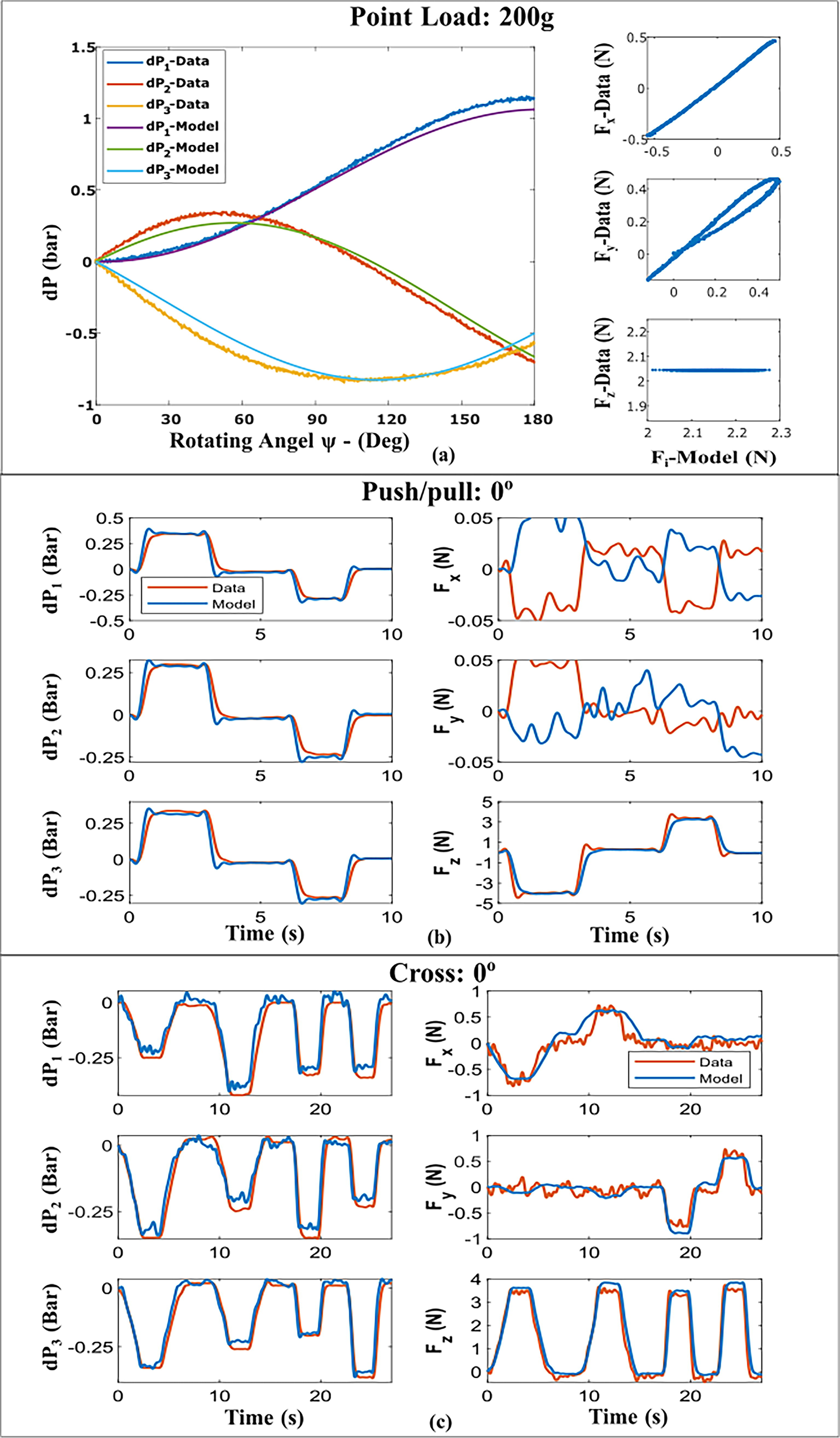
Results of
Figure 8b shows data obtained for θ =
Figure 9 illustrates all force data and estimations for the remaining bending configurations. Data-driven calibration was conducted for each configuration due to (1) the fluctuating magnitudes of forces (up to 6N) across all different experiments (affecting NA position) and (2) the geometric complexities of our segments. Table 1 summarizes the MAEs for the various configurations, which are generally consistent. To examine the robustness of calibration, random forces were estimated for
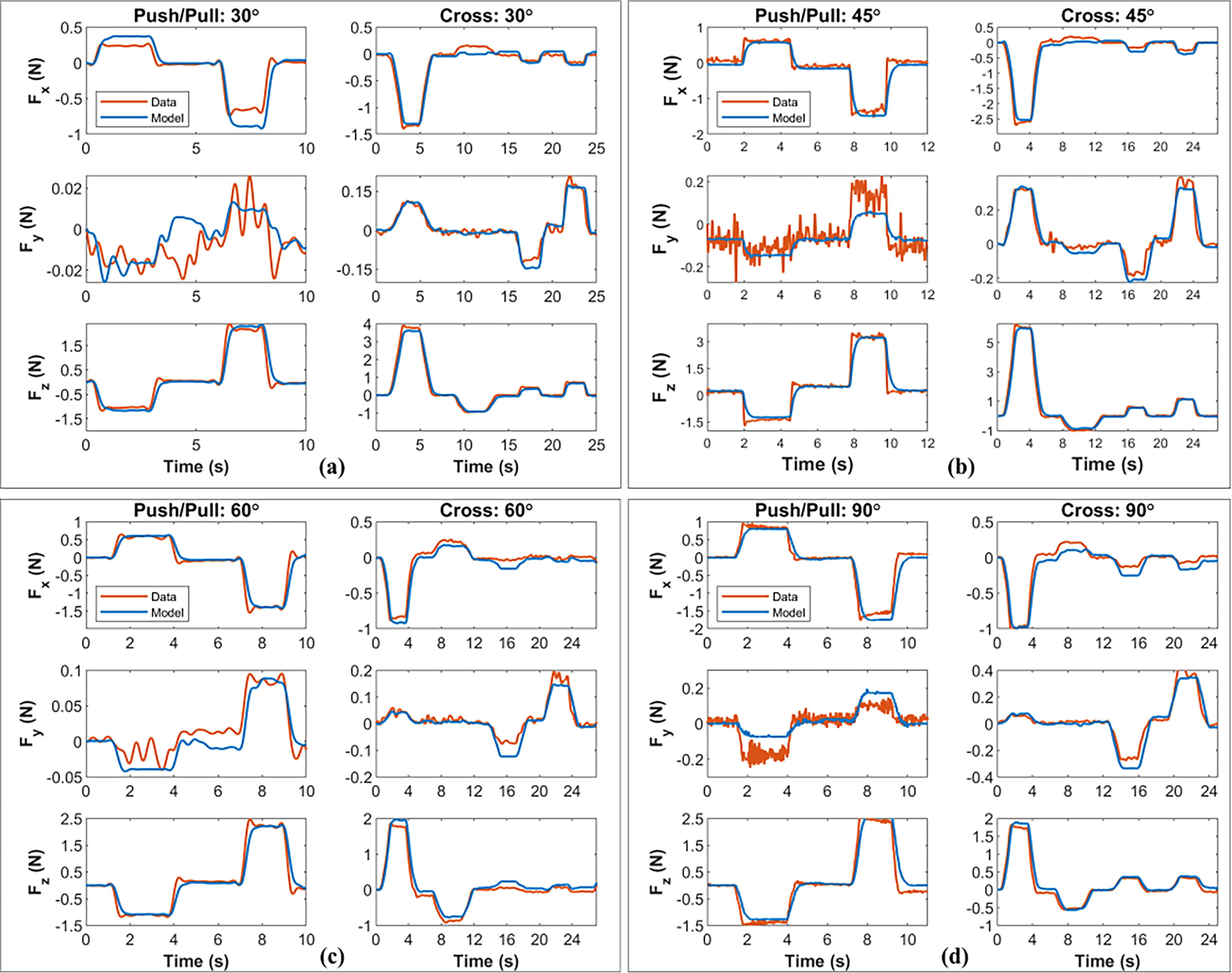
Experimental and model estimation results of the force vector
Steady-State Maximum Absolute Error of “Distributed Force” Prediction for Different Bending Configurations

Experimental and model estimation results of the force vector
Discussion
A. Neutral axis
Previous studies had effectively established mechanical and kinematic models for SFAs with an unconstrained fluidic chamber.19,46,62 The geometrical center of the chambers had been shown to shift toward the NA during inflation, consequently impacting the net bending moment.
19
Based on our findings, we postulate that the NA itself undergoes a shift. Even if the fluidic chambers are constrained and maintained fixed geometrical centers, the cross-sectional area and geometric nonlinearities still apply. Thus, the deflection angle cannot be assumed constant. This would affect our future force sensing characterization for configurations at bending planes along the
B. Chamber axial and radial kinematics
To the best of our knowledge, this is the first attempt to examine internal structure deformation of unconstrained fluidic chambers using CT imaging. The conservation of volume assumptions allows the development of (12) to estimate internal chamber expansion with relative accuracy. Chamber deformation should be uniform since we assume homogeneous mechanical properties. Yet, chamber expansion experiences a trapezoidal distribution and deforms out of a circular shape.
CT artifacts complicate the assessment of chamber deformation, but discrepancies in chamber expansion may be due to manual fabrication. The springs that reinforce the conduits are inserted postmolding and are plastically elongated toward the female end cap for enhanced gluing adhesion. Furthermore, the PET mesh sleeve has a nonuniform shape. Actuator fabrication and spring insertion will be revised to improve mechanical properties.
The trapezoidal distribution is probably also caused by trapped air inside the actuation chambers. Contrast agent and trapped air exhibit different buoyancy, causing air to rise toward the female end cap. Air has low X-ray attenuation, resembling the silicone body as a dark, low-density region making manual segmentation challenging. Furthermore, the presence of air violates volume constraint and incompressibility of actuation fluid. In general, air bubbles are a hurdle in microfluidic systems. 63 The tubes connecting the syringe pump and soft segment are long and have an inner diameter (ID) of 1.25 mm. Tubes with 3 mm > ID > 200 µm are classified as minichannels. 64 As fluid mechanics indicates, degassing these minichannels is exceptionally challenging, primarily due to the significant friction between the fluid and the tube wall. This high friction also creates pressure losses and is why the hydraulic circuit in our experiments was reduced using solenoid valves.
C. Actuation pressure
The performance of (14) in estimating
D. Force estimation
Our comprehensive modeling, which accounts for nonlinearities, allows intrinsic force sensing using fluidic pressure feedback with an MAE of 0.32N. Since geometric nonlinearities affect NA location, the algorithm derived here can be considered accurate only for the examined maximum bending and force magnitude (
The compliant PBFSS faces challenges transitioning to real-life applications due to the complex physical phenomena involved. Obtaining curved configuration kinematics relies on the assumption of constant curvature,47,68 but curvature may vary due to the fabrication method or external forces. 69 Our future focus on force estimation involves integrating fluid flow sensors for dynamic capture and increased data collection. Machine learning techniques with analytical equations will then be utilized to enhance the robustness of our G matrix and identify trends across configurations.70,71 In addition, we will explore the application of forces along the length of the silicone body.
Conclusion
This study leverages hydraulic fluid as a dual-role medium to meet the growing demand for highly flexible actuators and sensors. We introduce analytical methods to estimate the actuation pressure and the pressure variations caused by two external force types (concentrated and distributed) in various segment configurations. CT scan images are used to examine the internal deformation of the unconstrained actuation chambers—a novel approach that has not been previously undertaken. Furthermore, the research underlines the importance of accounting for cross-sectional and geometric nonlinearities, offering insights that enhance the design, manufacturing, and modeling of soft robots. Our proposed force sensing algorithm achieves high accuracy with an MAE of 0.32N for forces up to 6N.
Footnotes
Acknowledgments
The authors would like to acknowledge the Centre for Artificial Intelligence and Robotics (CAIR) in Hong Kong for providing facilities and equipment used in some of the experiments conducted.
Authors’ Contributions
D.M.: Conceptualization, methodology, software, formal analysis, investigation, data curation, writing—original draft, visualization. G.Z.: Methodology, investigation. S.W.: Investigation, resources; W.H.: Investigation, resources. L.L.: Conceptualization, writing—review and editing, supervision. B.Y.: Formal analysis. W.X.: Writing—review and editing, supervision. H.L.: Conceptualization, writing—review and editing, supervision, project administration, funding acquisition.
Author Disclosure Statement
No competing financial interests exist.
Funding Information
This research is funded by an internal King’s College London (KCL) grant from CDT in Surgical & Interventional Engineering, by the National High-Level Hospital Clinical Research Funding (2022-PUMCH-C-012) from Peking Union Medical College Hospital, by the CAMS Innovation Fund for Medical Sciences (2023-I2M-C&T-B-008), and the InnoHK program. The PET/CT scanning equipment is funded by a Wellcome Trust grand (WT 084052/Z/07/Z).
References
Supplementary Material
Please find the following supplemental material available below.
For Open Access articles published under a Creative Commons License, all supplemental material carries the same license as the article it is associated with.
For non-Open Access articles published, all supplemental material carries a non-exclusive license, and permission requests for re-use of supplemental material or any part of supplemental material shall be sent directly to the copyright owner as specified in the copyright notice associated with the article.