
Abstract
Constant development of soft robots, stretchable electronics, or flexible medical devices forces the research to look for new flexible structures that can change their shapes under external physical stimuli. This study presents a soft robotic structure that can change its shape into different three-dimensional (3D) configurations in response to electric current flown through the embedded liquid-metal conductors enabling electromagnetic actuation. The proposed structure is composed of volumetric pixels (voxels) connected in series where each can be independently controlled by the inputs of electrical current and vacuum pressure. A single voxel is made up of a granular core (GC) with an outer shell made of silicone rubber. The shell has embedded channels filled with liquid metal. The structure changes its shape under the Lorentz force produced by the liquid metal channel under applied electrical current. The GC allows the structure to maintain its shape after deformation even when the current is shut off. This is possible due to the granular jamming effect. In this study, we show the concept, the results of multiphysics simulation, and experimental characterization, including among other techniques, such as 3D digital image correlation or 3D magnetic field scanning, to study the different properties of the structure. We prove that the proposed structure can morph into many different shapes with the amplitude higher than 10 mm, and this process can be both fully reversible and repeatable.
Introduction
Robots in the modern society are expected to possess more abilities that enable a more efficient way of interaction with the surroundings, including humans, in an increasingly natural way compared to what we have observed and expected so far. Conventional design principles used in robotics have been substantially constrained by the use of rigid materials for the base structures. However, a recent increase in the research interest by the worldwide scientific community has been significantly focused on the development of soft robotic designs, with a strong trend to establish a field going beyond the traditional boundaries of engineering. In the context of a wide range of applications, robotics emerges as a promising field of research in both industries and fundamental studies, including biomimetic designs. 1 Soft robotics holds a great potential for practical implementation in natural environments. Studies on soft bioinspired designs, such as robots that float, walk, fly, and so on, have been presented in the literature to this day, for example, Nguyen et al., 2 Nguyen and Ho, 3 Schmitt et al., 4 Xiang et al., 5 and Yang et al. 6
One of the most common features of bioinspired solutions is shape morphing coupled with variable stiffness, 7 which resembles solutions adopted by a variety of natural living organisms. Many different phenomena provide both of these capabilities. There are many shape-shifting or morphing mechanisms that use methods of actuation by temperature,8,9 pressure,10,11 or light. 12 Both of natural designs and human-crafted ones, including electromagnetic (EM),13,14 electrostatic, 15 or even the pure mechanical phenomena (origami structure), 16 can be used to change the shape. The change of stiffness, on the other hand, can be realized by magnetorheological electrorheological fluids 17 or different types of jamming effects, like fiber, 18 layer, 19 or granular. 20
Despite their unique advantages, the above solutions clearly have particular drawbacks, that is, including relatively long response times in case of pneumatic solutions (usually longer than 0.5 s), 21 high activation voltages in the level of thousands of volts in case of dielectric actuators, 22 or the limitation in creating smooth and continuous structures in case of origami structures.7,16,23
One solution that could partially address the aforementioned drawbacks are soft EM actuators,14,21,24 where traditional copper wires are replaced by microfluidic circuits made of liquid metal alloy, for example, eutectic gallium indium (EGaIn) or Galinstan. 25 Such a structure works in a way similar to a direct current motor from which the Lorentz force is induced by placing an electrical conductor in the proximity of a magnetic field. This type of actuation is fast (even 10 times faster than pneumatic solutions) 26 and relatively easy to control. As it was shown in the work, 21 when liquid metal channels were placed in a flexible matrix made of highly deformable elastomer, a bending angle of higher that 45° can be obtained with a relatively low current of ∼3A. The clear advantages of this type of actuators encouraged researchers to use them in morphable structures, the foreseen programmable matter. Such a solution is presented in the article, 27 where multiple liquid metal circuits have been used to create a morphable plate.
Analyzing liquid metal actuators, the limitations associated with high force values seem to be most problematic. For example, in the article, 21 the authors were able to obtain the actuation force of only 0.071 N using a coil with 10 turns. This drawback in the use of a liquid metal conductor is further exacerbated by the fact that the conductivity of liquid metal (e.g., EGaIn) is in the order of magnitude lower compared with copper. 25 Due to the Joule heating, this is limited by the maximum current and time; otherwise, the structure simply overheats and gets damaged. Due to the small values of the Lorentz force, the only possibility to obtain the desired large deformations is the high flexibility of the structure, which causes that the structure after deformation is not able to transfer external loads, greatly limiting its use.
A way of challenging the engineering problems that can be encountered in such structures could be proposed in the form of the mechanism of variable stiffness, such as granular jamming. 20 This type of solution was proposed by the authors in their previous study, 26 where a liquid metal actuator coupled with granular jamming core allowed it to stiffen after deformation was introduced into the system. Unfortunately, this structure had only a single control channel, consequently not allowing to morph the structure into complex shapes, such as the ones demonstrated in the work. 27
To overcome these limitations, a structure composed of many independent electrical circuits, connected in series, is proposed in this study. This configuration allows the structure to morph in a continuous manner into different three-dimensional (3D) shapes and to stiffen itself using granular jamming. Such a structure could offer rapid and reversible shape morphing with the advantage of precision and speed control compared to mechanical,28,29 thermal, 30 or chemical 31 methods. The proposed stiffening mechanism could be also more effective than the solution of a similar design. 27
The article is divided into three main parts. The “Materials and Methods” section part describes the general concept of the proposed structure, the manufacturing process, and testing and simulation methodology. The part covering the “Results” section of our study presents the experimental and simulation results of the deformation data. The “Conclusions” section part closes the article with the summary of the results and the discussion on the future work.
Materials and Methods
General concept
The proposed structure consists of volumetric pixels (voxels) connected in series. The analyzed sample is composed of four voxels but can be scaled to larger structures. The key limit of this design is the number and the placement of the electrical leads. Each voxel forms a separate electrical circuit that can be independently controlled, and thus, different shapes can be created. The structure is made of silicone rubber (Ecoflex 00-20; Smooth-On Inc., Macungie, PA, USA) containing microchannels filled with liquid metal. 32
Between the liquid metal coils, there is a granular core (GC) filled with ground coffee, which was chosen for good mechanical properties 33 and the particle size appropriate to the dimensions of the sample. Each voxel has an independent pneumatic control, which enables its shape to be frozen, after deformation is introduced due to the electric current flowing through the coils, resulting in producing the Lorentz force when in the proximity of a magnetic field. The structure concept is shown in Figure 1, and the detailed dimensions are provided in the Supplementary Data. The dimensions of the samples, similar to those shown in articles,21,26 were based on the limitation of the manufacturing process optimized to achieve a deformation of at least 10 mm.
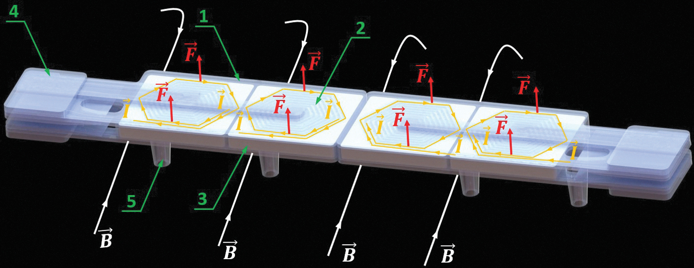
Programmable structure concept: the composite structure consists of four series-connected volumetric pixels (voxels) that can be independently controlled. Each of the voxels consists of two planar coils that enable shape morphing by Lorentz force and a GC enabling it to be “frozen” in its shape after deformation: (1) outer shell made up of Ecoflex 00-20, (2) planar coil made up of liquid metal, (3) coffee grain's core. Letter I-current, B-magnetic field, and F-resulting Lorentz force. GC, granular core.
When the structure is placed in a magnetic field, the initially flat, two-dimensional (2D) plate (Fig. 2a) can be programmed to transform into various 3D shapes (Fig. 2b, c). It can be realized by the Lorentz force generated by flowing the input current (I) through the liquid metal (
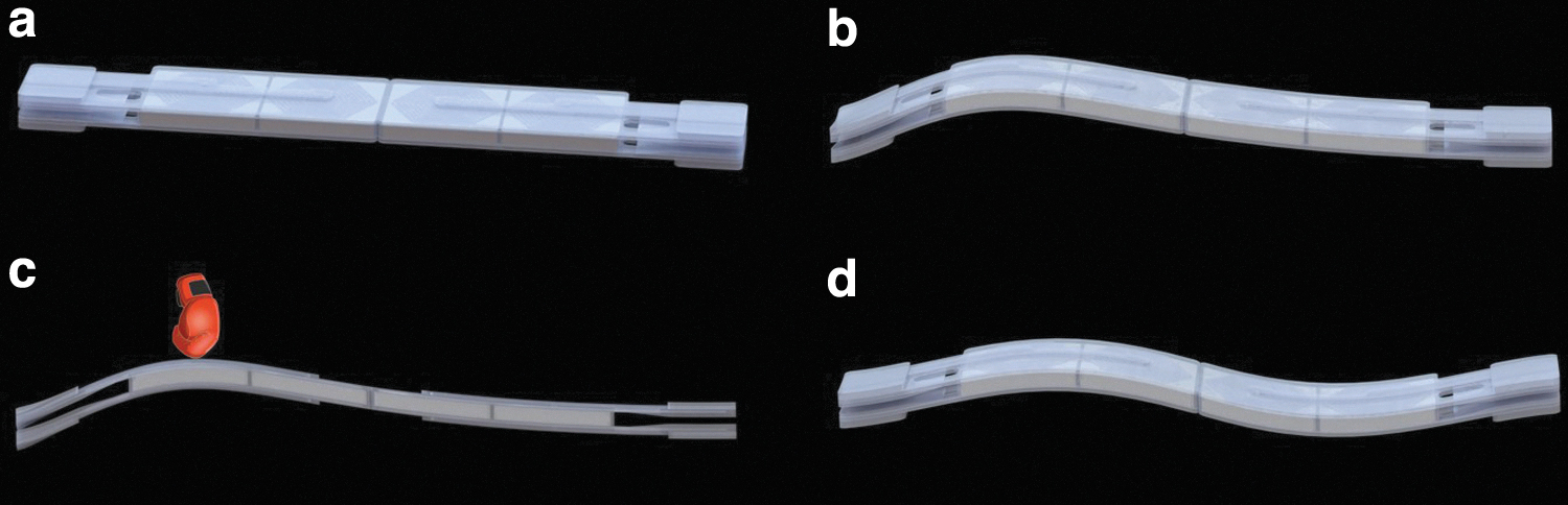
Programmable structure operation shape:
Sample fabrication
The sample fabrication process was conducted in the following manner. The first step was to design the molds for the parts of the sample. This was done with a 3D modeling software package (SolidWorks; Dassault Systemes, Waltham, MA, USA). The molds were then fabricated using fused deposition modeling (FDM) printer and akrylonitryl-co-butadien-co-styren polymer. The surface of the fabricated molds was additionally smoothed by immersing the molds into acetone to reduce the hatching effect from the FDM process. Silicone rubber compound (Ecoflex 00-20; Smooth-On, Inc.) 34 was used to produce the element of the samples through molding. After assembling the sample modules, the GC was formed from coarsely ground coffee, and the modules were put together into a complete sample. The fabrication steps are depicted in Figure 3 and in Supplementary Movie S1.

Fabrication procedure of structure components:
Tests
During the empirical tests, the sample was placed in the magnetic field generated by two permanent bar neodymium magnets (30 × 30 × 200 mm) and was powered by the Korad KD3305D power supply. The main goal was to check the structure's morphing capability, which was realized by applying current in different circuits. The sample deformations for the different modes were recorded by a 3D digital image correlation (DIC) system (Dantec Dynamics, Denmark) equipped with two cameras and Istra4D software that allowed for deformation or strain calculations. More information can be found in the Supplementary Data.
An important element of the research was also to examine the distribution of the magnetic field in the sample area, which was carried out by the MagCam magnetic field scanner. These tests were especially vital for comparison with the results of the numerical simulations. The MagCam equipment allows to measure the magnetic field vector (
Multiphysics simulation
To prove the concept and enable further development of the structure, multiphysics simulations using the coupling of EM and mechanical solvers in commercial finite element package LS-DYNA, were performed.
35
The model used includes two permanent bar magnets meshed with the size 3 mm and constant coercive equal to
The liquid metal was included in the model with the electrical conductivity properties which were calculated based on the geometry of the microchannel geometry (Supplementary Data), and the electrical conductivity of EGaIn equals to 
 where
where
Constrains are applied at the lower and the upper surfaces of the sample (3 degrees of freedom: x, y, and z displacement) as marked in the Figure 4. Depending on the chosen deformation mode, the input current was applied in the appropriate circuit. In each simulation, the current increased linearly, as a function of time from 0 to 2.5A in 0.2 s which is in line with the test conditions. The permanent magnets' poles are analogous to the test conditions.

Model for multiphysics simulation, including: permanent magnets, sample with GC, silicone coating, and liquid metal winding.
Based on the prepared model, the EM and the mechanical solvers perform the calculations. First, the EM solver using Maxwell's equations
37
determines the distributions of the magnetic fields and based on the equation
Results
Figure 5 shows that the sample, initially flat, can transform into various 3D shapes. Three different modes, with images of before and after deformation in each shape, are visualized. In addition to this, the displacement maps in the axis perpendicular to the initial position of the sample measured with the DIC system and their predictions using numerical simulation are presented. In addition, a graph comparing the displacements of selected points as a function of current for the test and simulation is shown.

3D shapes transformed from programmable structure. Experimental results (optical images and 3D-DIC) and simulation prediction of selected three representative 3D shapes transformed from planar structure in nonuniform magnetic field created by two permanent block magnets. 3D, three-dimensional; DIC, digital image correlation.
The shape I, similar to the C-shape, was obtained by passing the input current in the two central voxels, and the magnets were facing each other with the same poles (N–N). The maximum deformation amplitude that was gained in this mode with the current of 2.5A was equal to 10.2 mm. The shape II, similar to an S-shape, was obtained by applying the current in the second and the fourth voxels with an opposite polarity. The configuration of the magnets was analogous to that of the shape I. In this shape, the maximum deformation with the current of 2.5A was equal to 5.2 mm. The shape III was obtained by applying the current in the third voxel but with a different magnet polarity (S–N). The maximum deformation for this mode was equal to 7.1 mm with the current of 2.5A.
Good correlations between the empirical and the simulation results were achieved for each mode and over the entire current range. The maximum error of deformation, calculated according to the formula

Displacement of point 2 shape III in function of time under cyclic loading. Measurement for 25 cycles is shown.
Figure 7 shows the maps of the magnetic field both recorded by MagCam scanner and obtained through simulations. The area between the two magnets (Fig. 7a) at their topmost level (Fig. 7b) was measured. In the same area, the mesh, with the properties of air, was added in numerical model, and the results of this procedure are shown in Figure 7c. In general, the magnetic field distribution is similar in the test and the simulation. The maximum value of magnetic field for the test and the simulation is equal to 0.322 T and 0.339 T, respectively. The lowest value is in the middle and equals to 0.162 T (test) and 0.154 T (simulation). Based on these results, it can be seen that the error is lower than 5%.

Numerical prediction and empirical test of magnetic field (B) distribution
The load-bearing capability after jamming was also checked. Tests were performed for the structure deformed in a similar way to the shape I (5). The sample was tested, with the displacement of 10 mm, under several different vacuum pressures (0.095, 0.06, 0.06, 0.04, and 0.02 MPa). For each force versus deformation and data were collected (Fig. 8d). Tests for each vacuum pressure were repeated thrice. The nonlinear force-displacement characteristics can be seen for each vacuum pressure, with the highest amplitude of 4.62 N. In addition, the nonlinear characteristic can be seen when the maximum load transfer capability is considered. The maximum amplitude changes in the range 0–4.62 N (Table 1). The sample was able to transfer loads for vacuum 0.02 MPa, but in the case of the atmospheric pressure, it collapsed under its own weight, as shown in Figure 8b. In addition, to make the description more universal, the simplified bending stiffness was calculated according to the formula
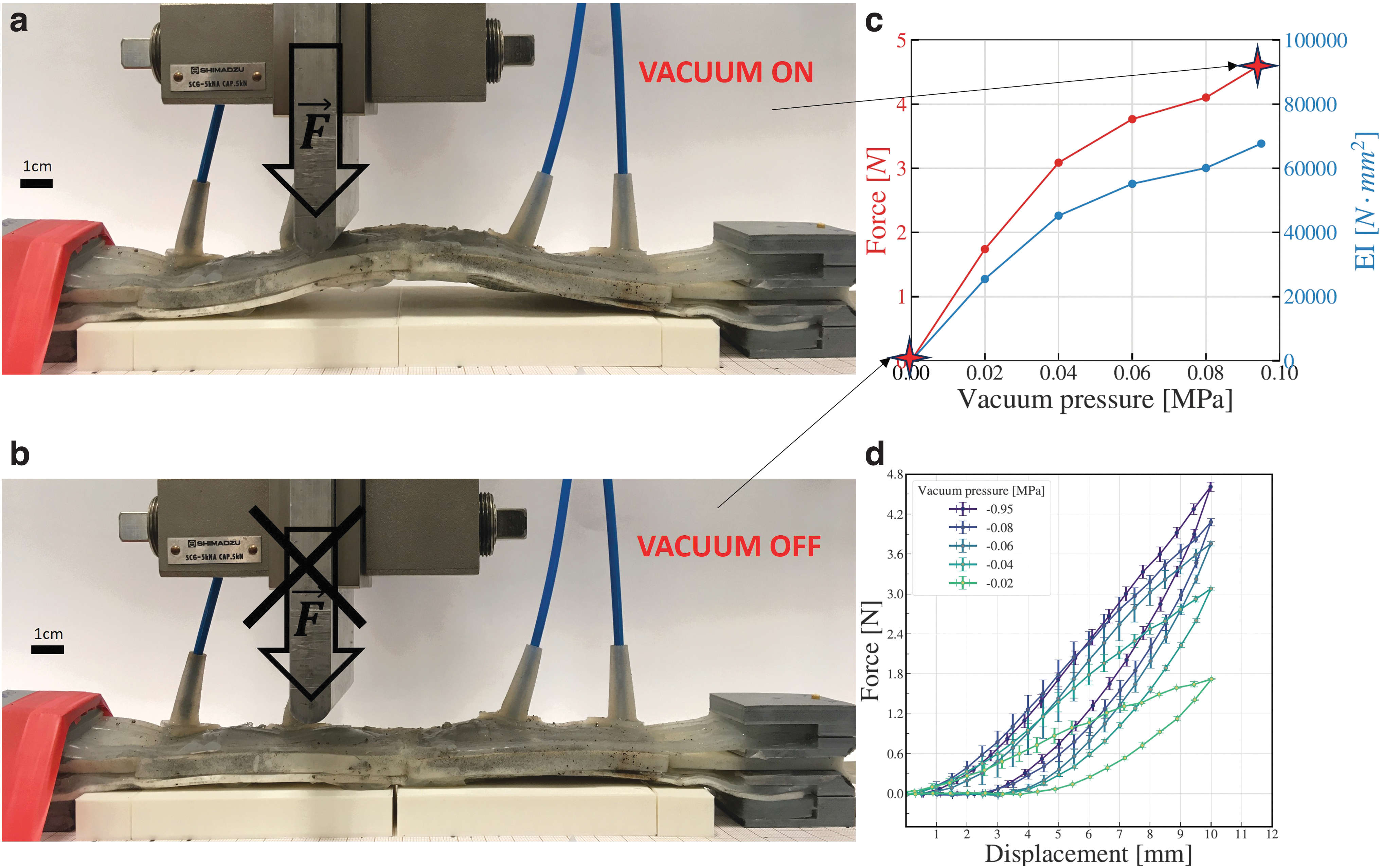
Shape fixation:
Vacuum Pressure Versus Maximum Load Transfer Force
The GC is mainly responsible for the stiffening's mechanism but it was also tested if the core could dissipate heat and thus reduce the temperature of the outer coils. The temperatures for two sample configurations with and without GC were measured. Figure 9a and b shows the temperature distributions for both samples where the maximum value is equal to 49°C and 41°C for sample without and with the GC, respectively. Figure 9c and d shows the average temperatures (averaged over the surface of the coil) as a function of time (20 s and five different current levels) for the two sample configurations. It can be seen that for the maximum current the temperature change was from about 26°C to 49°C and 34.5°C for the sample without and with the GC, respectively. Figure 9e shows the maximum temperature increment as a function of current. It can be seen that general curve's shape is

Thermal measurement for sample with and without GC. Temperature distribution for coil without
The proposed structure could be used to build soft floating robots, for example, in the shape of a fish. It can exhibit fish-like motions when the current is applied to the coil for multiple cycles, providing the opportunity to deform repeatedly, as seen in a real-life aquatic animal. The GC could change the swimming mode by stiffening the individual voxels and consequently increase the performance. 38 This structure could also function as a floating gripper that can easily stiffen its structure by applying vacuum after surrounding the target object. Examples of potential motions and visualization of the prototype are shown in Figure 10. In addition, the robotic motions are presented in Supplementary Movie S3. The proposed structure could be also used as morphable legs for a soft robot or a robotic gripper. Preliminary visualizations of such applications are presented in Supplementary Data.

Soft fish-like robot.
Conclusion
In this study, we demonstrated that 3D transformation of a soft structure can be achieved using soft EM coils made of fabricated using room-temperature liquid metal embedded in a self-morphing structure. Despite the fact that only three shapes are shown in this work (C-shape, S-shape, and twisting-shape), assuming the change of the input current, as well as the magnetic field and the vacuum pressure in four independent circuits, it is possible to obtain a variety of configurations (even assuming 10 levels of control with a total of 8 channels we can obtain
In addition, it was shown that it is possible to significantly stiffen the structure and thus increase its load carrying capacity. The structure is able to carry a load of 4.62 N at the maximum pressure, which is as high as twice the force of the previously developed structure with a similar size, 27 which realized the stiffening mechanism using the phase change gallium showing the maximum load of 2.25 N. In addition, the granular jamming process can be several times faster than the cooling process of gallium.
It was proven that the GC plays a role not only as a stiffening mechanism but also as a heat sink thus increasing the range of possible currents and operation time (Joule heating effect minimization). The GC allowed for reduction of the temperature of the silicone surface by over 35%, for the current of 5A for 20 s.
This work also shows new methods of empirical research and simulation, especially magnetic field scanning. Although prior works21,27 have analyzed the distribution of the magnetic field, the measurements were usually made with a single-hall probe and the distribution was determined only by simulation. Our research allowed us to experimentally determine the distribution and then to compare it with the results of the simulation, which were consistent. We also conducted multiphysics simulation. Usually, in similar research, mechanical and EM solvers have been used separately. 27 Thanks to the use of a coupled EM and mechanical solver, we were able to determine the Lorentz force (based on the actual distribution of the magnetic field and current) and consequently the structure's displacements and stresses at each integration time step. Therefore, it was possible to find a good correlation between the numerical prediction and the 3D-DIC measurement in the whole range of the input current in a strongly inhomogeneous magnetic field (lower than 5%).
A potential application of the proposed structure is shown in Figure 10. The continuous streamlined design can be a good nature-like mechanism for building floating/swimming robots. Due to the ability to control the voxels separately, we can achieve different swimming modes. The stiffening mechanism can also be helpful, which on one hand can cause other movements of the fish, as in the prior work, 38 or be used in an event that the fish is to stiffen after completing a mission (e.g., if it is to work in the gripper mode). Of course, such a structure has some drawbacks, such as pneumatic tubing, which may disturb the motion of swimming, but the design of tubes with a small diameter and high elasticity could significantly decrease this effect.
The proposed morphable structure demonstrated the feasibility and the functionality as a self-morphing structure using EM actuation in a soft structure. However, there is still room for improvement. To achieve a better structural performance, the miniaturization process would be viable. It could be done by changing the manufacturing process, for example, using a 3D printing process. 39 In addition, it would be worth developing the structure with multiple voxels connected in parallel, as well as in series (to obtain more complex shapes). Finally, it should be mentioned that the major limitation of the current structure is the necessity of using external equipment. Although the external power and the vacuum supply are not too problematic to use, the magnetic field generator is a major clear hurdle in the proposed applications. Therefore, in the future, it would be worth to consider a structure that would be integrated with its own magnetic field generator, for example, flexible permanent magnets similar to those shown in the work. 14
Nevertheless, the proposed structure has a potential in terms of a platform on which various significant soft robots could be built.
Footnotes
Authors' Contributions
P.B.: Conceptualization (lead), investigation (lead), methodology (lead), project administration, funding acquisition, visualization (lead), and writing (lead). L.P.: Investigation, resources, visualization, methodology, and writing. S.G.C.: Investigation, visualization, and writing. P.P.: Visualization. Y.L.P.: Review and consulting.
Author Disclosure Statement
No competing financial interests exist.
Funding Information
The research was funded by POB Technologie Materiałowe at Warsaw University of Technology within the Excellence Initiative: Research University (IDUB) programme: Grant name: Technologie materiałowe 2.
References
Supplementary Material
Please find the following supplemental material available below.
For Open Access articles published under a Creative Commons License, all supplemental material carries the same license as the article it is associated with.
For non-Open Access articles published, all supplemental material carries a non-exclusive license, and permission requests for re-use of supplemental material or any part of supplemental material shall be sent directly to the copyright owner as specified in the copyright notice associated with the article.