
Abstract
Snails employ a distinctive crawling mechanism in which the pedal waves travel along the foot and interact with the mucus to promote efficient movement on various substrates. Inspired by the concavities on the pedal wave, we develop a new bionic snail robot that introduces transverse patterns in a longitudinal wave to periodically change the friction. The poroelastic foam serves as flexible constraint and fills the robot's internal cavity. It contributes to the bending action, and maintains the thinness and softness of the robot. Then, the model of the robot's single segment is built utilizing the Euler–Bernoulli beam theory. The model aligns well with the experimental data, thereby confirming the effectiveness of soft constraints. The evaluation of pedal wave is conducted, which further guides the optimization of the control sequence. The experiments demonstrated the robot performing retrograde wave locomotion on dry substrates. Notably, shear-thickening fluids were found to be suitable for this particular crawling pattern compared with other mucus simulants, resulting in direct wave locomotion with a 49% increase in speed and a 33% reduction in energy usage. The load capacity of the soft snail robot was also enhanced, enabling it to carry loads up to 2.84 times its own weight. The use of mucus in crawling also brings valuable insights for the enhancement of other biomimetic robots.
Introduction
Snails exhibit a unique movement strategy known as wet adhesive locomotion, 1 which involves the generation of a traveling pedal wave that interacts directly with a thin layer of mucus.2,3 The rheological properties of natural mucus play a crucial role in pedal waves,4,5 allowing snails to adapt to various substrates and conserve energy during locomotion.6,7 Besides, some snail can perform the retrograde wave, 8 namely the propagation of the pedal wave occurs in the opposite direction to the snail's movement. Those features have led researchers to explore the development of biomimetic robots capable of navigating complex environments.
The researchers designed the snail robot using longitudinal waves to mimic the propagation of pedal waves. Implementing the longitudinal wave is relatively straightforward, and it can be achieved using discrete modules that move longitudinally in a coordinated sequence. These modules can be driven by a variety of mechanisms, including shape memory alloy wires, 9 cams, 10 servo motors, 11 negative pressure,12–14 and positive pressure. 15 A continuous sheet made of light-powered material 16 was also designed for this purpose.
In the case of longitudinal waves, the direction of vibration aligns with the propagation, ensuring that the contact area between the gastropod and substrate remains relatively constant during movement. Thus, Bingham fluids such as Carbopol 94017 and Laponite RD12,13 were employed as simulated mucus. This simulated mucus allows the snail robots to create regions of flow by locally shearing it, while the remaining mucus effectively adheres to the solid substrate.
To generate the continues wave, the transverse waves were introduced. Researchers generated smooth transverse waves using rotating helixes,9,18,19 screw cylinders, 20 and slider cranks, 21 all of which projected advancing sine waves. Despite the relative simplicity of these mechanical methods, the prototypes tend to be rigid. Such rigidity, while maintaining a consistent wave shape, cannot adaptively adjust to diverse environments, like changing amplitude to accommodate different gap heights. However, soft robotics brings novel solutions to this problem, enabling the generation of soft transverse waves.
As for fiber-reinforced structures,22,23 Masahiro et al. innovatively developed a “wave sheet” utilizing a distinct configuration of three tubes. Each tube was axially constrained by inextensible threads and collectively enveloped in a one-way stretch sleeve.24–26 Pneumatic network geometry27–29 is another classical principle. The intuitive idea of binding two single-direction actuators together to achieve body fluctuations was presented. 30 Further, Lior et al. developed a traveling wave based on a complex network of channels. They cast an elastic body embedding a multichannel core made of polyvinyl acetate, and then dissolved the core to form air channels.31,32
The position and density of these channels are crucial to wave formation and require precise calculation. Other research introduced sliding cable-driven, 33 piezoelectric beam, 34 magnetic driving methods, 35 among others. While many soft robots exhibiting transverse wave movement patterns have been developed, their interaction with mucus remains an area to be explored.
In this work, we develop a snail robot that exhibits a mixed movement pattern. Drawing inspiration from the traveling concavities on the snail's foot36,37 and the significant frictional changes between the foot and substrate,10,11,38,39 we incorporated a transverse pattern into the longitudinal wave. This modification periodically alters friction, thereby enabling retrograde wave locomotion on dry substrates. Moreover, our experiments indicated that shear-thickening fluids serve as suitable mucus simulants for this mixed movement pattern, realizing direct wave locomotion. Regarding the structural design, we utilized poroelastic foam to fill the robot's internal cavity, which acts as a flexible constraint. This design ensures the robot remains soft without fiber wrapping, also simplifying the manufacturing process by avoiding complex networks. This combination of features brings the snail robot closer to its natural counterpart, thus contributing to our understanding of gastropod locomotion.
Design Principle and Fabrication Process
The principle of crawling
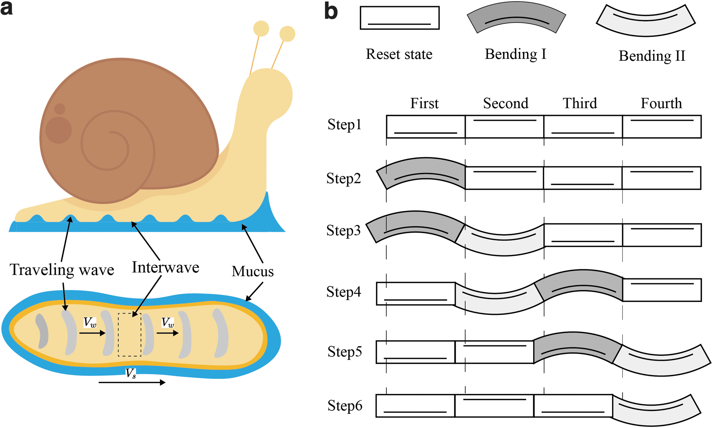
In the study of soft snail robots, it is essential to understand the unique locomotion mechanism exhibited by these gastropods. As shown in Figure 1a, the contraction of foot muscles plays a crucial role in this process, resulting in pedal waves that combine alternating traveling waves and stationary interwaves. In detail, the traveling waves consist of concavities, while the stationary interwaves maintain a flat surface.
The mechanism of snail crawling.
Parker initially confirmed the presence of concavities through the observation of air bubbles trapped beneath the foot mucus. 40 These bubbles were observed to be drawn toward the center and subsequently elongated longitudinally, suggesting the presence of a periodic suction and press effect. With the advancements in modern instruments, the pedal wave was accurately measured using laser sheet illumination and high-speed camera imaging techniques. 2 The interwave speed was found to be nearly zero, while the traveling wave speed was evident. Moreover, the concavities are important in changing the friction, generating a net propulsion.
Inspired by the traveling concavities and anisotropic friction, the foot is discretized into distinct segments arranged sequentially. The bending principle of each segment is simple, based on the asymmetrical extension of the top and bottom layers. However, the bending states hold significant importance. As shown in Figure 1b, the reset state indicates high potential friction, and both Bending I and Bending II indicate low potential friction. Besides, the bottom layer in Bending I remains unelongated, representing the stationary interwave, whereas the bottom layer in Bending II elongates, indicating the traveling wave.
As illustrated in Figure 1c, four segments are connected in an alternating Bending I and Bending II order to mimic the pedal wave, and the locomotion logic proceeds as follows:
Step 1: In the initial status, all the segments are in reset state.
Step 2: The first segment bends as Bending I without elongation, resulting in low potential friction.
Step 3: The second segment bends as Bending II with elongation since its bottom is elastic, pushing the first segment forward.
Step 4: The first segment resets with increasing potential friction. The third segment bends as Bending I, turning to low-friction status.
Step 5: The second segment starts to reset, pulling the third segment forward. Simultaneously, the fourth segment bends as Bending II, elongating to push the segments forward.
Step 6: The third segment is in reset state, and the fourth segment starts to reset.
It should be noted that the snail robot crawls to the left in a retrograde wave, as the wave is driven from left to right. Interestingly, with the appropriate mucus, the snail robot crawls in a direct wave, as discussed in the Snail Robot Crawling Experiment section.
Fabrication process of snail robot
The fabrication process for the soft snail robot is as follows. First, a bone was made of platinum-catalyzed silicone rubber (Ecoflex 00–30, Smooth-On Inc.) and cast into a polyamide mold (Fig. 2a). The cured bone consists of four segments (Fig. 2b). A lost-salt process41,42 was used to create the poroelastic foams, using Dragon Skin 20 as the matrix material and 20–30 mesh salt as the porogen. The mass ratio of Dragon Skin 20 to salt is 1:2.5, resulting in a porosity of 52% (Supplementary Data).

The fabrication process of the soft snail robot.
The mixture was compacted into four segments and aligned on the bone's surface (Fig. 2c). After curing, the mixture was put into an ultrasonic cleaner with hot water to dissolve the salt particles in the foam (Fig. 2d). Hand squeezing and scrubbing are recommended to accelerate the dissolution. The foams were then rinsed with clear water to remove residual salt and dried in a vent. In the next step, four gauzes were embedded to control the bending direction.
As illustrated in Figure 2e, two pieces of gauze were placed on the foam's top layer, and Ecoflex 00-30 was poured to cover the surface with a 3 mm-thick layer. Similarly, the other two pieces of gauze were placed on the bottom surface of the remaining two foams, and the bottom surface was sealed with a 3 mm thickness of Ecoflex 00-30. The silicone elastomer embedded with the gauze exhibits strong tensile resistance while remaining flexible. The cross-section of a segment and a closeup picture of the poroelastic foam are shown in Figure 2f.
Soft Restriction
Foam-reinforced structure
Figure 3a shows a segment where the gauze is embedded at the bottom layer without any foam filling. Under 20 kPa of pressure, the bottom layer, acting as a strain-limited layer, exhibits minimal stretching behavior, while the top layer expands freely up to 20 mm, similar to a balloon (Fig. 3b). In such a setup, there is an absence of a bending moment. To address this issue, the segment is filled with poroelastic foam internally. The poroelastic foam acts like a tension spring, and pulls the top and bottom layers together, preventing uncontrolled expansion. As a result of the vertical restraint, the top layer is forced to stretch horizontally under high pressure.
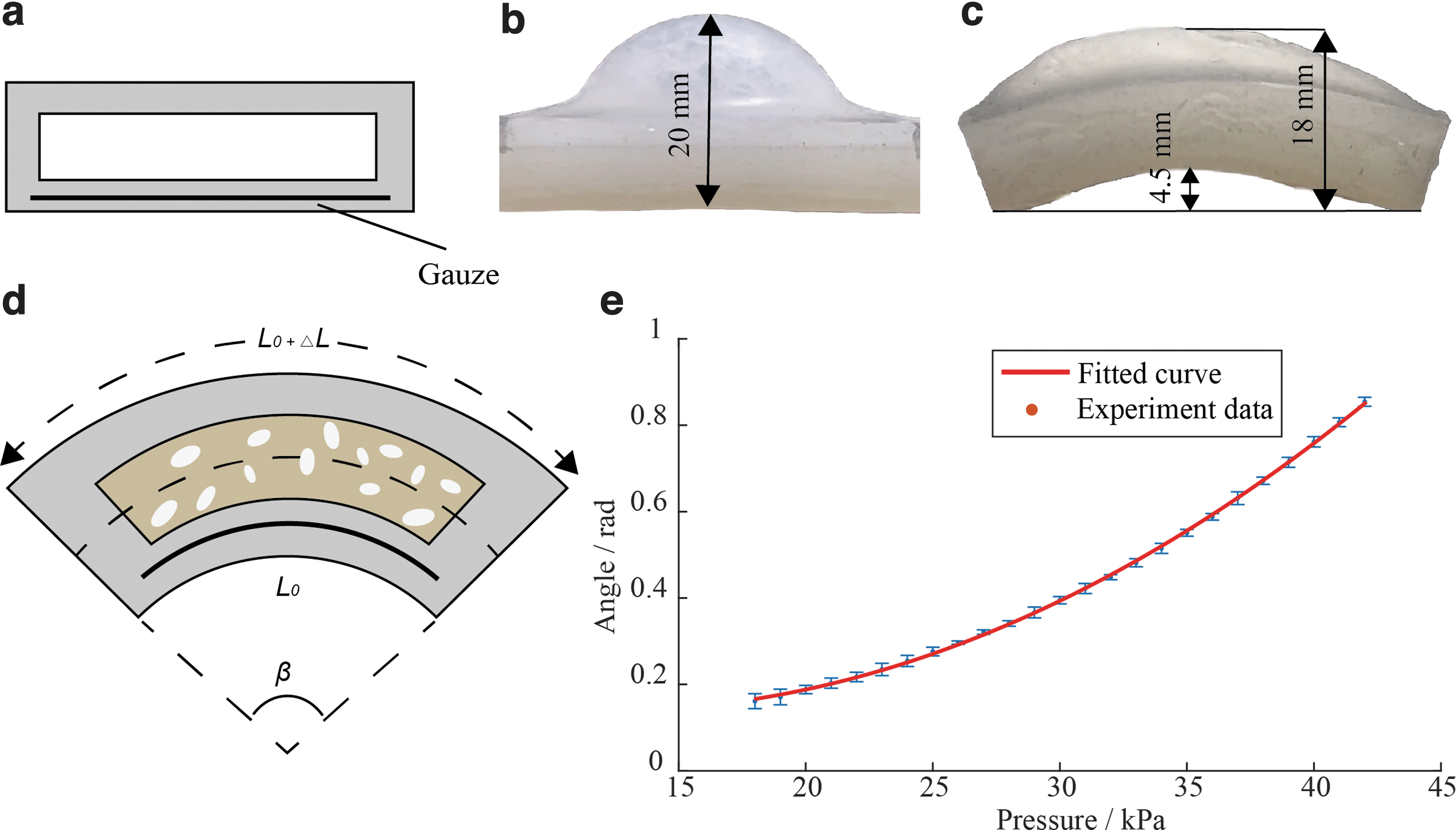
Illustration of the poroelastic foam's function and the bending model.
Consequently, the bending moment is created as the lengths between the top and bottom layers differ. As shown in Figure 3c, under 42 kPa pressure, the maximum height of the bottom layer reaches 4.5 mm, and the maximum height of the top layer is 18 mm. Since the thickness of the segment is 10 mm, the vertical deformation of the poroelastic foam is 18–4.5–10 = 3.5 mm. Thus, the poroelastic foam effectively limits the deformation of the top and creates a bending moment. The 3.5 mm vertical deformation is inevitable due to the elasticity of the poroelastic foam.
The bending model
The single segment can be modeled based on the Euler–Bernoulli beam theory, as a simply supported beam subjected to a uniform distribution of loads. As shown in Figure 3d, the bending curvature
where M represents external bending moment, E is the mean Young's modulus, I is the second moment of inertia of the cross-section.
The inelasticity of gauze leads to a bending moment M:
where P is the pressure, G is defined as the product of two factors: the cross-sectional area of the foam cut along the length direction and the distance of the stress point offset from the center.
Combining Equations (1) and (2), we obtain:
Thanks to the vertical restriction of poroelastic foam, the top layer almost stretches lengthwise, thus the elongation
where L0 is the original length.
The bending angle
Substituting Equations (3) and (4) into Equation (5), we obtain the following:
Thus,
Motion Analysis of Soft Robot
Evaluating wave quality is crucial for tuning control parameters. This section introduces a method to assess traveling waves and provides optimized control parameters based on this analysis.
Wave analysis
The wave equation is suitable for both transverse waves and longitudinal waves, as well as our mixed wave pattern.
where
As illustrated in Figure 1c, the snail robot crawls a constant distance within a single period. The velocity v can be derived from the following equation:
where d and f are the thickness of a segment and wave frequency, respectively.
The evaluation of the wave The wave Every harmonic component is formed by superposition of two waveforms with the same frequency and amplitude, the same vibration direction, and the opposite propagation direction.
Based on assumption 1, we obtain
where
Using assumption 2,
where an and bn are coefficients,
Further,
It is easier to further analyze the data in the complex plane:
where
The complex representation of
TWR is defined as follows
44
:
The closer
Wave optimization
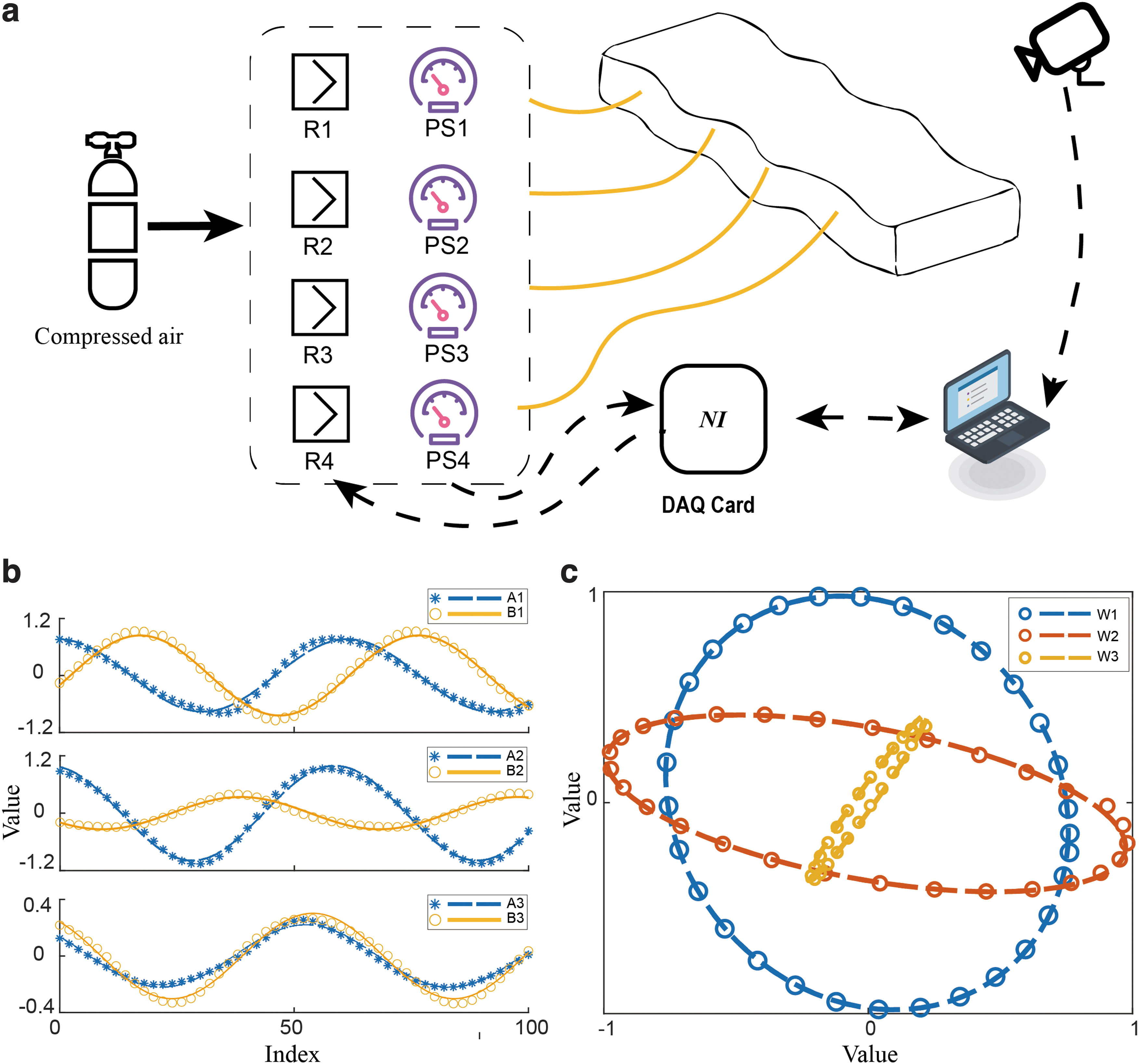
The experimental setup, as shown in Figure 4a, utilized proportional valves (VEAB-L-26D7-Q4-V1-1R1; Festo) to precisely regulate the compressed air supplied to the four inlets of the snail robot. The operation of these proportional valves was controlled by an analog signal generator (DAM3060C; ART Technology), which outputted a four-way voltage signal. A pressure sensor (DP101A; Panasonic) recorded the pressure and transmitted the analog signal to be read by the DAQ (USB-6210; National Instruments). The experiment employed a 1080P camera (
The experimental setup and results for wave optimization.
A sinusoidal wave was generated from head to tail using four phase-shifted pressure sources, represented as follows:
The experiment was conducted by varying
In our experiments, we highlight the optimal case where
Using Equation (14), we calculated
The other results are shown in Table 1. When
Traveling Wave Ratio Parameters of Different Shifting Phases
TWR, traveling wave ratio.
Snail Robot Crawling Experiment
Experiments were performed in which the soft snail robot was made to crawl on a dry substrate and also with a mucus simulant. The impact of using both Bingham fluids and shear-thickening fluids as mucus substitutes was subsequently compared.
Crawling on the dry substrate
With optimized phase shifting, the snail robot crawled on the dry substrate (black flocked velvet fabric). The snapshots of the snail robot's crawl in a period are shown in Figure 5a, which are consistent with the logical sequence in the Design Principle and Fabrication Process section. It is important to emphasize that the snail robot represented a mixed wave pattern propagating toward the right, while crawling to left. This phenomenon is known as a retrograde wave. The bending action might lead to misinterpretation, potentially causing an incorrect perception of a pure transverse wave propagating toward right. Viewed from a different perspective, if the robot's motion were a transverse wave, the snail robot would be expected to crawl toward the right.

The snapshots and heatmap of the soft snail robot crawling on the dry substrate.
The snapshots at t = 3, 6, 9 s are shown (Fig. 5b), and the heatmap (Fig. 5c) presents the bone line
The speed for different frequencies (f = 0.5–1.5 Hz) is shown in Figure 7c. The velocity exhibits a linear relationship with frequency in the range of 0.5–0.9 Hz, satisfying Equation (8). When
Crawling with Bingham fluid
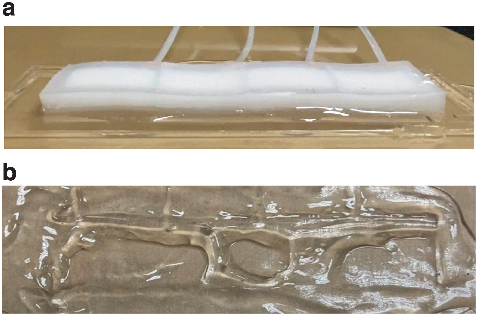
Laponite RD at a concentration of 5% is a widely recognized Bingham fluid and has been deployed in several snail robots moving in a longitudinal wave pattern.10,12,13 Despite its frequent use, the experiment suggests that 5% Laponite RD is not suitable for our snail robot locomotion. As illustrated in Figure 6, few amount of 5% Laponite RD persisted beneath the robot after a period of fluctuation. It can be inferred that the 5% Laponite RD was periodically sheared under the robot, flowing toward regions of lower shear stress and subsequently solidifying around the robot. This behavior suggests that Bingham fluid is unable to support the snail robot's locomotion when it periodically lifts away from the substrate and drops back.
The application of 5% Laponite RD as a mucus simulant for the snail robot.
This result also provides further inspiration. The crawling motion of this snail robot involves a combination of transverse and longitudinal waves as explained above. While the Bingham fluid is suitable for longitudinal wave moving pattern, the introduction of transverse waves induces a pronounced shear stress, causing the Bingham fluid to fail in supporting the robot's movement. This observation sparked a significant inspiration: How can the shear stress from transverse waves be harnessed to drive the snail robot's movement forward? Consequently, we opted for a different fluid with contrasting properties, one that solidifies under shear stress, thus offering the necessary support for the snail robot's movement.
Crawling with corn starch suspensions
We proposed an alternative approach for the snail robot prototype, utilizing shear-thickening fluids as a simulant, specifically using corn starch suspensions (Fig. 7a). Figure 7b illustrates the mechanics of crawling in shear-thickening fluids. As the air pressure increases, the robot lifts actively getting rid of the viscidity of starch suspensions. Conversely, when the air pressure decreases, the robot passively drops back to the substrate. During the drop period, the starch suspension is subjected to the shear force and hardens, and then changes the snail robot's movement direction. As a result, the snail robot exhibits the direct wave.

The application of corn starch suspensions as a mucus simulant for the snail robot.
The concentration of the starch solution is the key parameter, influencing the interaction force. Crawford et al 46 revealed a transition from continuous to discontinuous thickening behavior at 52.5 wt.%. To weigh off the liquidity and the shear-thickening properties, we prepared three starch suspensions with concentrations close to this turning point. These were 22 g cornstarch dissolved in 20 g water (52.38 wt.%), 23 g cornstarch dissolved in 20 g water (53.49 wt.%), and 24 g cornstarch dissolved in 20 g water (54.54 wt.%). In the experiments, we employed the shift phase optimization from the previous section, varying the frequency f from 0.2 to 1.8 Hz in increments of 0.1 Hz, to measure the robot's moving speed at each frequency.
Figure 7c presents the crawling speed of the snail robot at various frequencies and corn starch suspension concentrations. When the snail robot crawls on the 52.38 wt.% corn starch suspension, its speed increases almost linearly, approximately within the frequency range of f = 0.5 to 1.2 Hz, and remains unchanged at higher frequencies. When the robot crawls on the 53.49 wt.% corn starch suspension, it achieves a higher speed than that obtained on the 52.38 wt.% suspension, with the maximum speed reaching ∼1 mm/s. As the snail robot crawls on the 54.54 wt.% corn starch suspension, its speed curve overlaps with that of the 53.49 wt.% suspension for the frequency range of f = 0.5 to 1 Hz.
Beyond this range, the curve plateaus, maintaining a speed of ∼0.8 mm/s. This observation suggests that the 54.54 wt.% corn starch suspension generates a significant force when the wave frequency exceeds 1 Hz, which hampers the snail robot's crawling motion. Thus, the 53.49 wt.% corn starch suspension appears to be the most suitable mucus simulant for the snail robot. It allows the robot to achieve the highest crawling speed without hindering its motion at higher wave frequencies.
Based on those speed experiments, it can be stated that the mucus simulant speeds up the snail robot and saves the crawling energy. For instance, at a frequency f = 1.5 Hz, the crawling speed with mucus simulants (corn starch suspensions, 53.49 wt.%) is 1 mm/s, while the speed on a dry substrate is 0.67 mm/s. This indicates that the use of mucus simulants increases the speed by 49%. In terms of energy consumption, assuming the energy required for one fluctuation is a constant E0, the energy cost per unit distance with mucus simulants is
Moreover, the mucus simulant significantly augments the load capacity of the snail robot. On a smooth acrylic sheet, the robot was initially unable to initiate crawling and exhibited only in situ fluctuations (Fig. 7d). However, after applying a 53.49 wt.% corn starch suspensions onto the same acrylic sheet, the robot successfully conveyed a load of 108.18 g (Fig. 7e). Given that the robot itself weighs only 38.05 g, the mucus simulant enables the snail robot to convey a load ∼2.84 times its own weight.
Conclusion
The mechanics of snail locomotion present a complex interplay of factors. Snails have concavities on their feet that travel in the lengthwise direction and exhibit vertical curvature. Taking inspiration from this, we developed a bionic snail soft robot capable of wet adhesive locomotion. The snail robot crawls in a longitudinal wave pattern, employing vertical fluctuations to periodically alter its friction. The incorporation of poroelastic foams as internal soft constraints is key in enhancing bending, a strategy that is not only effective but also straightforward to implement, while preserving the robot's softness.
We further optimized the control sequence based on the TWR. The experimental results showed that the snail robot was capable of retrograde wave locomotion on dry substrates, while performing direct wave locomotion on corn starch suspensions, owing to the shear-thickening properties of the fluid. Notably, the use of shear-thickening fluids led to a 49% increase in speed, a 33% reduction in energy consumption, and an enhancement in load capacity to 2.84 times robot's own weight.
To more clearly reflect the contribution of this article, the primary performance metrics of several snail robots utilizing different actuation methods are detailed, as shown in Table 2. Pembury Smith and Ruxton 3 measured the speed of garden snails across different surface mediums, and the average speed clocked ∼1 mm/s. When compared with the rigid-body snail robot, 10 our soft snail robot is more similar to a natural snail, and both of them achieve a speed of 1 mm/s. It exhibits faster movement than two other pneumatic snail robots12,47 and a light-powered snail robot. 16 By utilizing shear-thickening fluid, our robot achieves a load-to-mass ratio that surpasses that of a snail robot constructed with fiber reinforcement. 24 This kind of mucus simulant can still provide valuable insights for the enhancement of other bionic robots.
Comparison of Nature Snails and Different Bionic Snail Robots
The mass of the robot is 154 g, with a load of 113 g, resulting in a load-to-mass ratio of 0.73.
LCE, liquid crystal elastomers.
The snail robot, which is capable of adapting to both dry and damp environments, has potential for applications in narrow crevice exploration and damp cavity investigation. The application of poroelastic foams further enhances its potential for high-pressure environments, potentially enabling deep-sea explorations, such as in submarine canyons. In future work, the implementation of ditaxic and tetrataxic waves could allow for on-the-spot turning capabilities.
Footnotes
Author Disclosure Statement
No competing financial interests exist.
Funding Information
This work is supported in part by the National Natural Science Foundation of China (Grant No. 92148205), and the Shenzhen Virtual University Park Basic Research Project (Grant No.2021Szvup025).
References
Supplementary Material
Please find the following supplemental material available below.
For Open Access articles published under a Creative Commons License, all supplemental material carries the same license as the article it is associated with.
For non-Open Access articles published, all supplemental material carries a non-exclusive license, and permission requests for re-use of supplemental material or any part of supplemental material shall be sent directly to the copyright owner as specified in the copyright notice associated with the article.