Legged robots have remarkable terrestrial mobility, but are susceptible to falling and leg malfunction during locomotion. The use of a large number of legs, as in centipedes, can overcome these problems, but it makes the body long and leads to many legs being constrained to contact with the ground to support the long body, which impedes maneuverability. A mechanism for maneuverable locomotion using a large number legs is thus desirable. However, controlling a long body with a large number of legs requires huge computational and energy costs. Inspired by agile locomotion in biological systems, this study proposes a control strategy for maneuverable and efficient locomotion of a myriapod robot based on dynamic instability. Specifically, our previous study made the body axis of a 12-legged robot flexible and showed that changing the body-axis flexibility produces pitchfork bifurcation. The bifurcation not only induces the dynamic instability of a straight walk but also a transition to a curved walk, whose curvature is controllable by the body-axis flexibility. This study incorporated a variable stiffness mechanism into the body axis and developed a simple control strategy based on the bifurcation characteristics. With this strategy, maneuverable and autonomous locomotion was achieved, as demonstrated by multiple robot experiments. Our approach does not directly control the movement of the body axis; instead, it controls body-axis flexibility, which significantly reduces computational and energy costs. This study provides a new design principle for maneuverable and efficient locomotion of myriapod robots.
Introduction
Animals exhibit agile locomotion using their legs and show remarkable terrestrial mobility for traversing diverse environments. Inspired by animal locomotion, many legged robots have recently been developed to achieve agile locomotion in various environments.1–7 In addition, legged robots are expected to be deployed in a wide variety of scenarios, such as search and rescue,8,9 hazardous environment operation and exploration,10,11 and planetary exploration.12–14 However, legged robots are susceptible to falling due to the intermittent repetition of foot contact and foot lift-off,15,16 which may result in the breakdown of mechanical and electrical components, from which it is difficult to recover. Furthermore, malfunction even in one leg greatly deteriorates their locomotor performance.17 To overcome these problems and achieve high traversability on rough terrain and high tolerance to falling and leg malfunction, greatly increasing the number of legs is useful, as observed in centipedes and millipedes.18–28
Although the use of a large number legs has advantages for legged robots, it makes the body long and complicates the interaction with the environment. In particular, many contact legs are physically constrained to remain on the ground to support the long body during locomotion, which impedes maneuverability. Recently, passive components in the body segments and legs have been suggested to contribute to agile myriapod locomotion.23,26,29 However, the underlying mechanism of agile locomotion using a large number of legs remains largely unclear from both biological and engineering viewpoints.30 Maneuverable locomotion for robots using a large number of legs remains challenging.
In addition to the maneuverability problem, the use of a large number legs greatly increases the number of degrees of freedom of robots, which makes motion planning and control difficult. In particular, conventional controllers precisely plan the motion of all degrees of freedom (e.g., how the long body is bent, where each foot touches the ground, the order in which the legs move) and control the robot to stabilize the desired motion.31,32 However, this approach requires huge computational and energy costs. Efficient locomotion for robots using a large number of legs is also challenging.
Recently, bio-inspired approaches, that is, the use of mechanisms elucidated from biological systems, have attracted attention to achieve high locomotor performance of legged robots.33–38 Among animals, cockroaches show incredibly agile locomotion using their six legs.30,39 It has been suggested that they manipulate the position of ground reaction forces entering the body to control the stability of a straight walk and that straight walk instability helps them to turn quickly.40,41 The dynamic instability induces rapid and large movement changes. Inspired by their turning strategy, this study proposes a control scheme for maneuverable and efficient locomotion of myriapod robots. Specifically, we made the body axis of a 12-legged robot flexible. Our previous study42 showed that changing the body-axis flexibility produces pitchfork bifurcation. This bifurcation not only induces the dynamic instability of a straight walk but also the transition into a curved walk. These bifurcation characteristics helped the myriapod robot turn quickly. In this study, the robot incorporates a variable stiffness mechanism into the body axis, which allows the robot to change its body-axis flexibility and control the bifurcation characteristics during walking. We developed a simple control strategy based on these properties, which enables the robot to achieve maneuverable and autonomous locomotion. Our approach does not directly control the movement of the body axis; instead, it controls body-axis flexibility, which largely reduces the computational and energy costs. This study provides a new design principle for maneuverable and efficient locomotion of myriapod robots.
Myriapod Robot
Robot
We used a multi-legged robot with 6 body segments and 12 legs (Fig. 1A, B). The developed robot43 was later improved.42,44 In this study, the robot newly incorporated a variable stiffness mechanism. This robot is composed of six modules (modules 1–6). The total mass and length are 9.1 kg and 135 cm, respectively. Each module has a single body segment and one pair of legs. The modules are connected passively through yaw joints (yaw joints 1–5), where torsional springs (spring constant of ki []) and potentiometers are installed. The angles of yaw joints are 0 when the modules are aligned. The gap between the modules is constant. Each leg consists of two links connected by pitch joints. The legs of module 1 have an additional yaw joint for a supplementary control of the walking direction during turning tasks. Each leg joint is controlled by an encoder-equipped motor. Module 1 possesses a laser range scanner (Hokuyo; URG-04LX) to get the relative positions of targets for turning.
Myriapod robot. (A) Photograph and (B) schematic model. This robot consists of six modules. Each module has one body segment and one pair of legs. The modules are connected by yaw joints onto which torsional springs are installed. Each leg is controlled by two pitch joints so that the leg tip follows a desired trajectory. A variable stiffness mechanism is incorporated into yaw joint 1. (C) Side view, (D) top view, and (E) schematic model of the variable stiffness mechanism.
The robot walked on a flat wooden floor covered by a vinyl mat to suppress slipping. An external computer (Intel Pentium 4 2.8 GHz, RT-Linux) controlled the robot with 2-ms intervals. The electric power and control signals were provided through cables, which were slack to avoid disturbing the locomotion.
Variable joint stiffness mechanism
In this study, our robot incorporated a variable stiffness mechanism45 in body-segment yaw joint 1 to autonomously change k1 during robot experiments. The variable stiffness mechanism consists of a ball screw mechanism and a linear tension spring (length: l, natural length: mm, spring constant: N/mm, and initial tension: N), as shown in Figure 1C–E. The ball screw mechanism is attached to the second module (module 2). One side of the spring is attached to the first module (module 1) at a distance of mm from yaw joint 1 (). The other side is attached to the nut of the ball screw mechanism, whose position p (distance from yaw joint 1) is controlled by an encoder-equipped motor (). From the spring tension and spring length , the joint torque produced by this variable stiffness mechanism is given by
Linearization using the joint angle around gives
As a result, the joint stiffness (torsional spring constant) k1 is approximated by
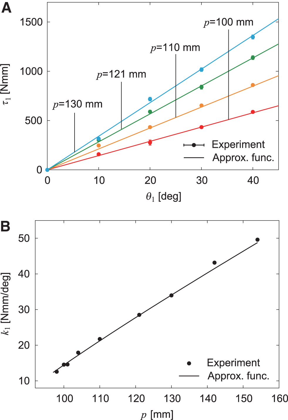
We investigated the properties of the variable stiffness mechanism installed in body-segment yaw joint 1. Specifically, we fixed the position p of the nut of the ball screw mechanism at various positions and measured the joint torque with respect to the joint angle . Figure 2A compares the results with the approximation function.43 In addition, we obtained the joint stiffness (torsional spring constant) k1 from the − relationship using the least squares method. Figure 2B compares the results with the approximation function.44 These experimental results were well fitted by the approximation function. We found that k1 can be changed from 12 to 50 Nmm/deg by controlling p in our system.
Variable joint stiffness in body-segment yaw joint 1. (A) Joint torque with respect to yaw joint angle depending on nut position p. The data points and error bars are the means and standard deviations, respectively, of five experimental results. (B) Spring constant k1 with respect to p. Experimental data were obtained using the least squares method for the − relationship.
Leg control for straight walking
We used the same controller for the legs as that in our previous study42,44 to make the robot walk in a straight line. Specifically, we controlled the two pitch joints of each leg so that the leg tip follows the desired trajectory composed of trajectories for the swing and stance phases (Fig. 1B). The trajectory for the swing phase consists of half of an elliptical curve starting from the posterior extreme position (PEP) and ending at the anterior extreme position (AEP). The trajectory for the stance phase consists of a straight line from the AEP to the PEP, and the leg tips moved at a constant speed parallel to the body segments. We used and s for the durations of the half elliptical curve and straight line, respectively, and 3 cm for the distance between the AEP and the PEP. We moved the left and right legs in antiphase in each module and used rad for the relative phase between the ipsilateral legs on adjacent modules. When the yaw joints of the legs in module 1 are fixed so that the leg tips move parallel to the body segments, the robot is expected to walk in a straight line with the body segments parallel to each other because the yaw joints of the body segments have torsional springs and the leg tips move parallel to the body segments at the same speed during the stance phase.
Instability and Bifurcation of Straight Walking
When large spring constants are used for the body-segment yaw joints, the robot keeps walking in a straight line as expected. Our previous study43 revealed that when all the spring constants for the body-segment yaw joints are reduced, the straight walk becomes unstable through Hopf bifurcation (this bifurcation changes the stability of an equilibrium point in a dynamical system by changing a parameter and creating a limit cycle46), and body undulations appear, which was verified by a Floquet analysis with a simple robot model. In addition, another previous study42 revealed that when only the spring constant k1 for yaw joint 1 is reduced, the straight walk transitions into a left- or right-curved walk through pitchfork bifurcation (this bifurcation changes the stability of an equilibrium point and creates two equilibrium points46), which was also verified by a Floquet analysis with a simple robot model.
In this study, we first confirmed the characteristics of this pitchfork bifurcation in our robot, which was then used for the controllers described in Turning Maneuverability and Autonomous and Maneuverable Locomotion sections below, by comparison with those in a previous study.42 Specifically, we used the same spring constant for body-segment yaw joints 2–5 ( Nmm/deg, ) and fixed the spring constant of body-segment yaw joint 1 during the experiments at , 17, 21, 28, or 41 Nmm/deg by a variable stiffness mechanism. All the body segments were set parallel to each other as the initial condition. We fixed the leg yaw joints in module 1 during the experiments.
When spring constant k1 was large ( Nmm/deg), the robot walked in a straight line (Fig. 3A, C, Supplementary Movie S1—Supplementary Appendix SA1 contains links to all movies). However, when k1 was small (, 17, 21, and 28 Nmm/deg), it walked in a curved line (Fig. 3A, D, E, Supplementary Movie S1) and both left- and right-curved walk were generated. Figure 4 shows the absolute angles of all the body-segment yaw joints for averaged over 5 s during the curved walk. These angles increase with , and all the yaw angles show similar trends. These results suggest that the straight walk becomes unstable and transitions into a curved walk by pitchfork bifurcation. By fitting these angle data with the square root of , the bifurcation point was estimated to be (standard error [SE]) Nmm/deg ( (SE) deg/Nmm) from five body-segment yaw joints. Figure 3B presents the radius of curvature r of the body axis during the curved walk for determined by , where L is the length of each body segment and is the angle of body-segment yaw joint i (). These bifurcation characteristics are similar to those in a previous study.42 These results indicate that we can manipulate the curvature of the body axis for a curved walk by adjusting k1 by pitchfork bifurcation.
Appearance of curved walk for small k1 values (Supplementary Movie S1). (A) Angle of yaw joint 1 averaged during curved walk for that implies pitchfork bifurcation and (B) radius of curvature r of body axis for . The data points and error bars are the means and SEs, respectively, of 10 experimental results. Dotted lines show the results of a previous study.42 Photographs for (C) straight walk for , (D) curved walk with small curvature for , and (E) curved walk with large curvature for . SE, standard error.
Absolute angles for yaw joints averaged during curved walk for . The data points and error bars are the means and SEs, respectively, of 10 experimental results. Dotted lines show the results of a previous study.42
Turning Maneuverability
Turning strategy using pitchfork bifurcation
Our previous study42 demonstrated that pitchfork bifurcation improves the maneuverability of a myriapod robot during a turning task in which the robot approached one target located on the floor in directions different from those where the robot was oriented. We next confirmed this using our robot and the same one-target task by comparing the results with those in the previous study.42
For any location of a target (relative angle and distance R), there is a unique radius of curvature for a curved walk with which the robot will reach the target (Fig. 5A). Since the radius of curvature r of the body axis monotonically decreases with as shown in Fig. 3B), is uniquely determined from . That is, when is used, the robot spontaneously approaches the target by the pitchfork bifurcation characteristics. This is an optimal turning strategy. However, this strategy is feedforward and depends on the initial conditions for the robot and target. In particular, the initial robot conditions determine the direction in which the robot turns (left or right) due to the pitchfork bifurcation characteristics, which indicates that this strategy does not guarantee the success of the turning task. Therefore, we also used a supplementary turning controller to approach the target using a laser range scanner and leg yaw joints of module 1 developed in our previous study44 (Supplementary Appendix SA2). This supplementary controller enabled the robot to approach the targets even when .
One-target task. (A) Schematic model of radius of curvature of curved walk with which the robot approaches a target with relative angle and distance R. (B) Trajectory of module 1 on the floor, (C) target distance, and (D) relative target angle of five experimental results for three spring constants with , m, m, and deg/Nmm (Supplementary Movie S2). (E) Evaluation criteria , , and for . The data points and error bars are the means and SEs, respectively, of five experimental results. Dotted lines show the results of a previous study.42 Photographs of (F) initial condition, (G) unsuccessful trial for , (H) successful trial for , and (I) unsuccessful trial for .
Turning performance in one-target task
For the initial condition in the one-target task, and m were used for the relative angle and distance between module 1 and target, respectively, which generated m and Nmm/deg ( deg/Nmm) (Fig. 5F). The spring constant of yaw joint 1 was fixed during the experiments at , 17, 21, 28, or 41 Nmm/deg by the variable stiffness mechanism and all the body segments were set parallel to each other as the initial condition. Figure 5B shows the trajectory of module 1 on the floor during the turning task for (), 21 (), and 41 Nmm/deg (). Figure 5C and D present the time profiles of the target distance and angle relative to the walking direction, respectively. We assumed that the robot reached the target when the distance was <0.15 m and considered this task to be successfully completed. When Nmm/deg (), it was difficult for the robot to change its walking direction and the trajectory of module 1 bulged outward, so that the robot could not reach the target (Fig. 5G, Supplementary Movie S2). When Nmm/deg (), the robot quickly changed its walking direction, but moved away from the target because of the small radius of curvature generated by pitchfork bifurcation, and thus could not reach the target (Fig. 5I, Supplementary Movie S2). By contrast, when Nmm/deg (), the robot successfully reached the target by the optimal curved walk generated by pitchfork bifurcation (Fig. 5H, Supplementary Movie S2).
To quantitatively clarify the turning performance dependence on k1, we employed three evaluation criteria, namely , , and , for five spring constants (, 17, 21, 28, and 41 Nmm/deg), as used in our previous study.42 Criterion is the target distance at 23 s (the earliest time when the task is successfully completed), which evaluates how successfully and quickly the robot approached the targets. Criterion is the absolute value of the target angle relative to the walking direction at 23 s, which evaluates how successfully and quickly the robot was oriented toward the targets. Criterion is the energy cost of actuators per unit of moving distance and the magnitude of walking direction change, similar to the performance criterion known as the cost of transport, which evaluates the energy efficiency during the task. Specifically, , where E is the energy cost calculated using the square of the motor torque as , and are the torques at the leg pitch joints in module j, at the leg yaw joints in module 1, and at the variable stiffness mechanism, respectively), D is the moving distance calculated by (D0 is the target distance at the initial condition), and is the magnitude of walking direction change calculated by ( is the absolute relative target angle at the initial condition). Figure 5E shows the results for compared with the results of a previous study.42 All criteria show minimum values around , indicating that the turning strategy using pitchfork bifurcation showed the best performance.
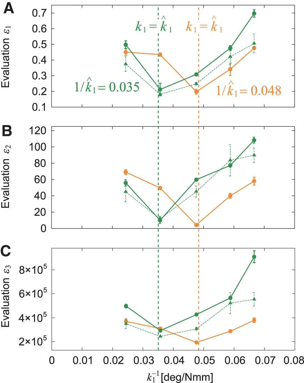
To verify the performance of the turning strategy using pitchfork bifurcation, we also performed the same experiment using different initial conditions for the target, namely and m, which yielded m and Nmm/deg ( deg/Nmm). Figure 6A–C compare the evaluation criteria , , and , respectively, for with those in a previous study.42 All criteria show minimum values around and show similar trends to those in Figure 5E.
Evaluation criteria (A), (B), and (C) for for two different conditions ( and deg/Nmm) for one-target task. The data points and error bars are the means and SEs, respectively, of five experimental results. Dotted lines show the results of a previous study.42
Autonomous and Maneuverable Locomotion
Two-target task for autonomous locomotion
Autonomous locomotion is required for legged robots to allow them to change their destination in accordance with the situation and then produce adequate behavior depending on the destination. We next tackled the autonomous locomotion capability of our robot. To examine whether our robot achieves autonomous locomotion and to evaluate its maneuverability during autonomous locomotion, we used two targets (targets 1 and 2) placed at different locations on the floor (Fig. 7A). The robot first approached the first target (target 1). After the robot had reached target 1 (i.e., the target distance was <0.15 m), the robot approached the second target (target 2). When the distance to target 2 was <0.2 m, the task was considered to be successfully completed.
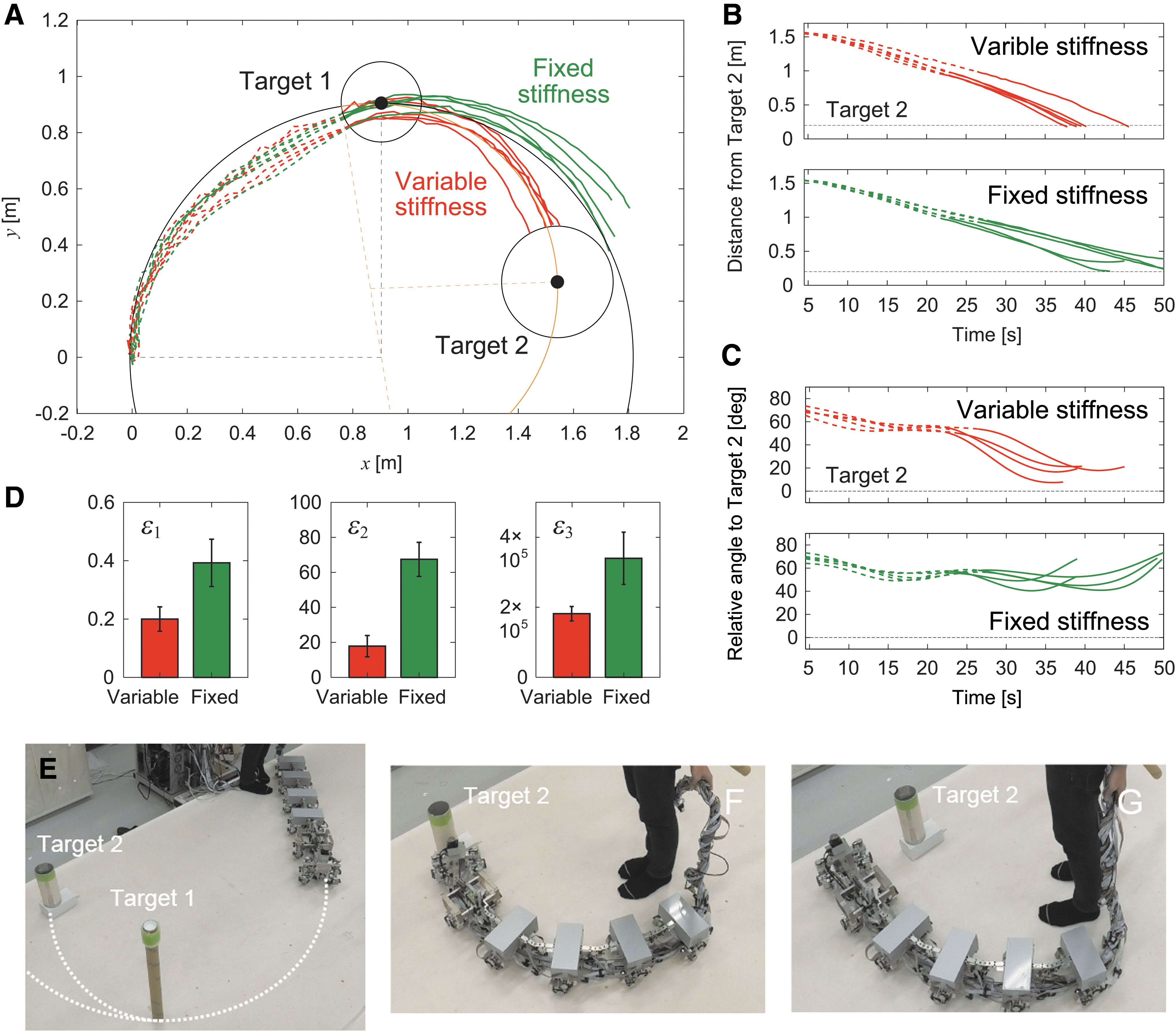
Two-target task with the same direction for targets. (A) Schematic model of radius of curvature for target 1 with relative angle and distance R1 and radius of curvature for target 2 with relative angle and distance R2. (B) Change of k1 depending on . (C–I) Experimental results for larger radius of curvature in target 2 with , m, m, deg/Nmm, , m, m, and deg/Nmm () (Supplementary Movie S3). (C) Trajectory of module 1 on the floor, (D) distance from target 2, and (E) relative angle of target 2 of five experimental results for variable and fixed stiffnesses. The dotted and solid lines indicate data before and after the robot reached target 1, respectively. (F) Evaluation criteria , , and . The data points and error bars are the means and standard deviations, respectively, of five experimental results. Photographs for (G) initial condition, (H) successful trial with changing stiffness, and (I) unsuccessful trial without changing stiffness.
Although the optimal joint stiffness was uniquely determined in the one-target tasks above, it is not necessarily the same between the two sequential approaches in the two-target tasks. Furthermore, the target direction (left or right) is not necessarily the same between the two approaches. As shown in Figure 3A, after the straight walk becomes unstable due to a change in k1, it transitions into a left- or right-curved walk by pitchfork bifurcation. Once a curved walk appears, the curve direction does not change unless large external forces are applied. Therefore, the situation in two-target tasks depends on the target direction.
Two-target task with the same target direction
In this study, we solved the problems related to optimal stiffnesses and target direction by controlling the joint stiffness of body-segment yaw joint 1, that is, we used a variable stiffness mechanism during locomotion. We began with the same target direction for the two approaches. At the beginning of the first approach to target 1, the robot determined the optimal stiffness as by calculating from the relative angle and the distance R1 of target 1 (Fig. 7A). After the robot reached target 1, it determined the optimal stiffness as by calculating based on the relative angle and distance R2 to target 2 (Fig. 7A) and changed k1 from to by the variable stiffness mechanism. The joint stiffness increased when and decreased when (Fig. 7B).
To examine the performance of the joint stiffness control, we used and m, which yielded m and Nmm/deg ( deg/Nmm), and and m, which yielded m and Nmm/deg ( deg/Nmm) (Fig. 7G). For this condition, . We compared cases with and without a change in k1 after the robot reached target 1. Figure 7C shows the trajectory of the first module on the floor for these two cases. Figures 7D and E show the time profiles for the distance from target 2 and the relative angle of target 2 with respect to the walking direction, respectively. Without a change in joint stiffness, the curved walk of the robot when approaching target 2 was almost the same as that when approaching target 1, and thus the robot could not reach target 2 (Fig. 7I, Supplementary Movie S3). In contrast, when the robot changed the joint stiffness to the second optimal value, it reached target 2 through sequential optimal curved walks generated by pitchfork bifurcation (Fig. 7H, Supplementary Movie S3).
To quantitatively clarify the difference in performance between the cases with and without a change in joint stiffness, we also compared three evaluation criteria, namely , , and (Fig. 7F), as used in the one-target tasks. Specifically, and were evaluated at 22 s after the robot reached target 1, and was calculated after the robot reached target 1. Furthermore, we examined whether changing the joint stiffness during the task results in better turning maneuverability than that obtained without changing it using these three criteria and a one-sided t-test with Bonferroni correction. The results indicated that all criteria showed smaller values when the joint stiffness was changed. The p-values for a one-sided t-test were calculated as for , for , and for (Bonferroni correction ), which suggests that changing the joint stiffness leads to better turning maneuverability.
We also performed the same experiment using different conditions for target 2, namely and m, which yielded m and 15 Nmm/deg ( deg/Nmm). For this condition, . We evaluated and 16 s after the robot reached target 1 and calculated after the robot reached target 2. The results show similar trends (Fig. 8, Supplementary Movie S4), which verifies the performance of the proposed controller using the variable stiffness mechanism.
Experimental results for two-target task with the same direction and smaller radius of curvature for target 2 with , m, m, deg/Nmm, , m, m, and deg/Nmm () (Supplementary Movie S4). (A) Trajectory of module 1 on the floor, (B) distance from target 2, and (C) relative angle of target 2 of five experimental results for variable and fixed stiffnesses. The dotted and solid lines indicate data before and after the robot reached target 1, respectively. (D) Evaluation criteria , , and . The data points and error bars are the means and standard deviations, respectively, of five experimental results. Photographs of (E) initial condition, (F) successful trial with changing stiffness, and (G) unsuccessful trial without changing stiffness.
Two-target task with different target directions
Next, we consider different target directions for the two approaches. After the robot reached target 1, it temporarily increased its joint stiffness by the variable stiffness mechanism to stabilize the straight walk (Figs. 9A, B). The robot then determined the optimal stiffness as by calculating based on the relative angle and distance to target 2, and changed k1 to by the variable stiffness mechanism (Fig. 9A). These two changes in joint stiffness allowed the robot to change the curve direction (Fig. 9B). As the duration for the temporal stabilization of the straight walk increases, the robot can change the curve direction. However, this changes the relative target position and limits the reachable space. That is, the success rate and reachable space of the task are a trade-off. We determined 14 s for the temporal stabilization of the straight walk through robot experiments so that the robot can change the left-right direction for various conditions.
Two-target task with different target directions. (A) Schematic model of radius of curvature for target 1 with relative angle and distance R1, radius of curvature for target 2 with relative angle and distance R2, and radius of curvature for target 2 with relative angle and distance when stabilizing the straight walk after the robot reaches target 1. (B) Two changes of k1. The straight walk is stabilized once to change the curve direction.“” indicates that the curve direction cannot change in this route. (C–I) Experimental results with , m, m, deg/Nmm, , m, m, deg/Nmm, (SE), (SE) m, (SE) m, and (SE) deg/Nmm (Supplementary Movie S5). (C) Trajectory of module 1 on the floor, (D) distance from target 2, and (E) relative angle of target 2 of five experimental results for stabilized and unstabilized straight walks. The dotted and solid lines indicate data before and after the robot reached target 1, respectively. Bold lines indicate stabilization of the straight walk. (F) Evaluation criteria , , and . The data points and error bars are the means and standard deviations, respectively, of five experimental results. Photographs of (G) initial condition, (H) successful trial with stabilizing the straight walk, and (I) unsuccessful trial without stabilizing the straight walk.
To examine the performance of this joint stiffness control, we used and m, which yielded m and Nmm/deg ( deg/Nmm), and and m, which yielded m and 28 Nmm/deg ( deg/Nmm) (Fig. 9G). For this condition, . We compared cases with and without stabilizing the straight walk after the robot reached target 1. Figure 9C shows the trajectory of the first module on the floor for the two cases. Figures 9D and E show the time profiles for the distance from target 2 and the angle of target 2 relative to the walking direction, respectively. Without stabilizing the straight walk, the robot could not change the curve direction after it reached target 1 and thus could not reach target 2 (Fig. 9I, Supplementary Movie S5). In contrast, when the robot temporarily stabilized the straight walk and then determined the second optimal stiffness, it reached target 2 through the optimal curved walk generated by pitchfork bifurcation (Fig. 9H, Supplementary Movie S5). The robot used (SE) and (SE) m, which yielded (SE) m and (SE) Nmm/deg ( (SE) deg/Nmm).
To quantitatively clarify the difference in performance between cases with and without stabilizing the straight walk, we compared three evaluation criteria, namely , , and (Fig. 9F). Specifically, and were evaluated 31 s after the robot reached target 1, and was calculated after the robot reached target 2. Furthermore, we examined whether stabilizing the straight walk for different target directions results in better turning maneuverability than that obtained without stabilizing it using these two criteria and a one-sided t-test with Bonferroni correction. The results indicated that all criteria showed smaller values when the straight walk was stabilized. The p-values for a one-sided t-test were calculated as for , for , and for (Bonferroni correction ), which suggest that temporarily stabilizing the straight walk leads to better turning maneuverability.
Autonomous locomotion
Although these experiments used at most two targets, the results suggest that the proposed method allows the robot to achieve maneuverable locomotion even for multiple sequential targets. That is, the robot achieves autonomous and maneuverable locomotion. To demonstrate this, we performed an experiment where the robot approached nine targets placed on the floor sequentially (Supplementary Movie S6).
Discussion and Conclusion
Maneuverability and efficiency are critical issues for legged robots. this study focused on dynamic instability to address these issues, inspired by the agile locomotion of cockroaches.40,41 Maneuverability is related to the ability to change movement direction. When the movement direction is destabilized during locomotion, the instability provides driving forces to rapidly change the movement direction and thus improves maneuverability. In addition to cockroaches, many animals are thought to use dynamic instability to enhance maneuverability in their locomotion. In particular, because the instability is determined by the body dynamics through interaction with the environment, it is outstanding in locomotion generated through aerodynamics and hydrodynamics, such as the locomotion of flying insects47–49 and sea animals.50–52 In addition to such biological systems, some fighter aircraft, such as the F-16, are designed to be aerodynamically unstable to increase maneuverability.53,54 The use of dynamic instability is thus useful from both biological and engineering viewpoints.
In addition to dynamic instability, this study used pitchfork bifurcation. General myriapod robots use actuators for controlling not only the leg joints but also body-segment joints and calculate the desired motion for all joints.31,32 However, this leads to huge computational and energy costs. In contrast, this study developed a myriapod robot, whose body-segment joints are passive because they use torsional springs rather than actuators. Pitchfork bifurcation generated a curved walk, whose curvature is controllable by the body-segment joint stiffness (Figs. 2 and 3). Because the generated curved walk was robust and the gait patterns quickly changed, the bifurcation characteristics greatly enhanced maneuverability (Figs. 5–8). Furthermore, manipulating the stability based on pitchfork bifurcation allowed the robot to change the turning direction (Fig. 9) and perform autonomous locomotion. Although the change in the spring constant of other yaw joints than yaw joint 1 also produces pitchfork bifurcation, we changed that of yaw joint 1 because it was the most effective in the experiments. Our approach does not directly control the movement of the body axis; instead, it controls the body-axis flexibility. These characteristics greatly reduce the computational and energy costs. Dynamic instability and pitchfork bifurcation are characteristics of the dynamical system embedded in our robot. The generation of robot movements by inherent dynamics rather than actuators is crucial for efficient locomotion.55,56 Our findings will provide a new design principle for maneuverable and efficient locomotion of myriapod robots. To further clarify the advantages and limitations of the proposed approach, in future studies, we would like to quantitatively investigate how robust the curved walk is, how long it takes to change the gait pattern, and what target arrangements are reachable.
Our robot mainly consists of standard metal and DC motors and is basically hard. Only the torsional springs in the body-segment yaw joints have soft characteristics. However, these soft elements governed the entire dynamics of the robot and created various types of locomotion, which greatly improved the performance. This seems to be a benefit seen in soft robots. We investigated the contribution of the proposed controller to maneuverable and efficient locomotion of a myriapod robot through robot experiments on a hard flat floor. In the future, it will be important to validate our design in more complex environments, such as rough terrain. In particular, although our robot has torsional springs in the body-segment yaw joints, more compliant components should be also incorporated into the body-segment pitch and roll joints and legs, as previously reported.26,27
Footnotes
Authors' Contributions
S.A. developed the study design. Y.Y. incorporated the variable stiffness mechanism into the robot. Y.Y., D.M., and K.O. performed the experiments. S.A., Y.Y., D.M., K.O., and M.A. analyzed the data in consultation with K.S. and K.T. S.A. wrote the article, and all the authors reviewed and approved it.
Author Disclosure Statement
No competing financial interests exist.
Funding Information
This study was supported, in part, by JSPS KAKENHI grant nos. JP17H04914, JP19KK0377, and JP20H00229; JST FOREST Program grant no. JPMJFR2021; and the Inamori Foundation.
Supplementary Material
References
1.
HwangboJ, LeeJ, DosovitskiyA, et al.Learning agile and dynamic motor skills for legged robots. Sci Robot, 2019; 4:eaau5872.
2.
IjspeertAJ.Biorobotics: Using robots to emulate and investigate agile locomotion. Science, 2014; 346:196–203.
3.
LeeJ, HwangboJ, WellhausenL, et al.Learning quadrupedal locomotion over challenging terrain. Sci Rob, 2020; 5:eabc5986.
4.
MastalliC, HavoutisI, FocchiM, et al.Motion planning for quadrupedal locomotion: Coupled planning, terrain mapping, and whole-body control. IEEE Trans Robot, 2020; 36:1635–1648.
5.
OwakiD, IshiguroA. A quadruped robot exhibiting spontaneous gait transitions from walking to trotting to galloping. Sci Rep, 2017; 7:277.
6.
ParkH-W, WensingPM, KimS. High-speed bounding with the MIT Cheetah 2: Control design and experiments. Int J Robot Res, 2017; 36:167–192.
7.
RaibertM, BlankespoorK, NelsonG, et al. BigDog, the rough-terrain quadruped robot. In: Proc. IFAC World Congress; 2008; pp. 10822–10825.
8.
HoffmanKL, WoodRJ. Myriapod-like ambulation of a segmented microrobot. Auton Robot, 2011; 31:103–114.
9.
NingM, MaZ, ChenH, et al.Design and analysis for a multifunctional rescue robot with four-bar wheel-legged structure. Adv Mech Eng, 2018; 10:1–14.
10.
ByrdJS, DeVriesKR. A six-legged telerobot for nuclear applications development. Int J Robot Res, 1990; 9:43–52.
ArmP, ZenklR, BartonP, et al. SpaceBok: A dynamic legged robot for space exploration. In: Proc. IEEE Int. Conf. Robot. Autom; 2019; pp. 6288–6294.
13.
RudinN, KolvenbachH, TsounisV, et al. Cat-like jumping and landing of legged robots in low gravity using deep reinforcement learning. IEEE Trans Robot, 38:317–328, 2021.
14.
WilcoxBH, LitwinT, BiesiadeckiJ, et al.Athlete: A cargo handling and manipulation robot for the moon. J Field Robot, 2007; 24:421–434.
15.
HiroseS.A study of design and control of a quadruped walking vehicle. Int J Robot Res, 1984; 3:113–133.
16.
RaibertM. Legged Robots That Balance. MIT Press: Cambridge, UK; 1986.
17.
CullyA, CluneJ, TaraporeD, et al.Robots that can adapt like animals. Nature, 2015; 521:503–507.
18.
AsoY, AiharaK, ItoK. Multi-legged robot for rough terrain: SHINAYAKA-L VI. In: Proc. Int. Conf. Adv. Mech. Syst.; 2019; pp. 136–141.
19.
ChongB, AydinYO, RieserJM, et al.A general locomotion control framework for multi-legged locomotors. Bioinspir Biomim, 2022; 17:046015.
20.
HoffmanKL, WoodRJ. Turning gaits and optimal undulatory gaits for a modular centipede-inspired millirobot. In: Proc. IEEE RAS EMBS Int. Conf. Biomed. Robot. Biomechatron.; 2012; pp. 1052–1059.
21.
HoffmanKL, WoodRJ. Robustness of centipede-inspired millirobot locomotion to leg failures. In: Proc. IEEE/RSJ Int. Conf. Intell. Robot. Syst.; 2013; pp. 1472–1479.
22.
KanoT, SakaiK, YasuiK, et al.Decentralized control mechanism underlying interlimb coordination of millipedes. Bioinspir Biomim, 2017; 12:036007.
23.
KohD, YangJ, KimS. Centipede robot for uneven terrain exploration: Design and experiment of the flexible biomimetic robot mechanism. In: Proc. IEEE RAS EMBS Int. Conf. Biomed. Robot. Biomechatron.; 2010; pp. 877–881.
24.
MasudaM, ItoK. Semi-autonomous centipede-like robot with flexible legs. In: Proc. IEEE Int. Symp. Saf. Secur.Rescue. Robot.; 2014.
25.
Miguel-BlancoA, ManoonpongP. General distributed neural control and sensory adaptation for self-organized locomotion and fast adaptation to damage of walking robots. Front Neural Circuits, 2020; 14:46.
26.
Ozkan-AydinY, ChongB, AydinE, et al. A systematic approach to creating terrain-capable hybrid soft/hard myriapod robots. In: Proc. IEEE Int. Conf. Soft Robot.; 2020; pp. 156–163.
YasuiK, SakaiK, KanoT, et al.Decentralized control scheme for myriapod robot inspired by adaptive and resilient centipede locomotion. PLoS One, 2017; 12:e0171421.
29.
DiazK, EricksonE, ChongB, et al.Active and passive mechanics for rugose terrain traversal in centipedes. J Exp Biol, 2023; 226:jeb244688.
30.
FullRJ, KubowT, SchmittJ, et al.Quantifying dynamic stability and maneuverability in legged locomotion. Integr Comp Biol, 2002; 42:149–157.
31.
TakahashiR, InagakiS. Walk control of segmented multi-legged robot based on integrative control of legs and 2-DoF active intersegment joints. Adv Robot, 2016; 30:1354–1364.
32.
WeiT, LuoQ, MoY, et al.Design of the three-bus control system utilising periodic relay for a centipede-like robot. Robotica, 2016; 34:1841–1854.
33.
AguilarJ, ZhangT, QianF, et al.A review on locomotion robophysics: The study of movement at the intersection of robotics, soft matter and dynamical systems. Rep Prog Phys, 2016; 79:110001.
34.
AoiS, ManoonpongP, AmbeY, et al.Adaptive control strategies for interlimb coordination in legged robots: A review. Front Neurorobot, 2017; 11:39.
35.
IjspeertAJ, CrespiA, RyczkoD, et al.From swimming to walking with a salamander robot driven by a spinal cord model. Science, 2007; 315:1416–1420.
36.
LiC, ZhangT, GoldmanDI. A terradynamics of legged locomotion on granular media. Science, 2013; 339:1408–1411.
37.
OthayothR, XuanQ, WangY, et al.Locomotor transitions in the potential energy landscape-dominated regime. Proc R Soc B, 2021; 288:20202734.
38.
SteingrubeS, TimmeM, WörgötterF, et al.Self-organized adaptation of a simple neural circuit enables complex robot behaviour. Nat Phys, 2010; 6:224–230.
39.
JindrichDL, FullRJ. Many-legged maneuverability: Dynamics of turning in hexapods. J Exp Biol, 1999; 202:1603–1623.
40.
ProctorJ, HolmesP. Steering by transient destabilization in piecewise-holonomic models of legged locomotion. Reg Chaot Dyn, 2008; 13:267–282.
41.
SchmittJ, HolmesP. Mechanical models for insect locomotion: Dynamics and stability in the horizontal plane-II. Application. Biol Cybern, 2000; 83:517–527.
42.
AoiS, TomatsuR, YabuuchiY, et al.Advanced turning maneuver of a many-legged robot using pitchfork bifurcation. IEEE Trans Robot, 2022; 38:3015–3026.
43.
AoiS, EgiY, TsuchiyaK. Instability-based mechanism for body undulations in centipede locomotion. Phys Rev E, 2013; 87:012717.
44.
AoiS, TanakaT, FujikiS, et al.Advantage of straight walk instability in turning maneuver of multilegged locomotion: A robotics approach. Sci Rep, 2016; 6:30199.
45.
UemuraM, MatsusakaK, TakagiY, et al.A stiffness adjustment mechanism maximally utilizing elastic energy of a linear spring for a robot joint. Adv Robot, 2015; 29:1331–1337.
46.
StrogatzSH.Nonlinear Dynamics and Chaos: With Applications to Physics, Biology, Chemistry, and Engineering. Perseus. Books: New York, NY, USA;. 1994.
47.
DickinsonMH, FarleyCT, FullRJ, et al.How animals move: An integrative view. Science, 2000; 288:100–106.
TaylorGK, KrappHG. Sensory systems and flight stability: What do insects measure and why?. Adv Insect Physiol, 2007; 34:231–316.
50.
FishFE, HurleyJ, CostaDP. Maneuverability by the sea lion Zalophus californianus: Turning performance of an unstable body design. J Exp Biol, 2003; 206:667–674.
51.
FishFE.Balancing requirements for stability and maneuverability in cetaceans. Integr Comp Biol, 2002; 42:85–93.
52.
WebbPW. Designs for stability and maneuverability in aquatic vertebrates: What can we learn? In: Proc. Int. Symp. Unman. Unteth. Subm. Tech.; 1997; pp. 86–108.
53.
AvanziniG, de MatteisG. Bifurcation analysis of a highly augmented aircraft model. J Guid Contr Dyn, 1997; 20:754–759.
54.
KwatnyHG, BennettWH, BergJ. Regulation of relaxed static stability aircraft. IEEE Trans Automat Contr, 1991; 36:1315–1332.
55.
CollinsSH, RuinaAL, TedrakeR, et al.Efficient bipedal robots based on passive-dynamic walkers. Science, 2005; 307:1082–1085.
56.
VuHQ, YuX, IidaF, et al.Improving energy efficiency of hopping locomotion by using a variable stiffness actuator. IEEE/ASME Trans Mechatron, 2016; 21:472–486.
Supplementary Material
Please find the following supplemental material available below.
For Open Access articles published under a Creative Commons License, all supplemental material carries the same license as the article it is associated with.
For non-Open Access articles published, all supplemental material carries a non-exclusive license, and permission requests for re-use of supplemental material or any part of supplemental material shall be sent directly to the copyright owner as specified in the copyright notice associated with the article.


 , and
, and