
Abstract
Despite increasing interest in minimally invasive surgical techniques and related developments in flexible endoscopes and catheters, follow-the-leader motion remains elusive. Following the path of least resistance through a tortuous and potentially delicate environment without relying on interaction with the surrounding anatomy requires the control of many degrees of freedom. This typically results in large-diameter instruments. One viable solution to obtain dexterity without increasing size is via multiple-point magnetic actuation over the length of the catheter. The main challenge of this approach is planning magnetic interaction to allow the catheter to adapt to the surrounding anatomy during navigation. We design and manufacture a fully shape-forming, soft magnetic catheter of 80 mm length and 2 mm diameter, capable of navigating a human anatomy in a follow-the-leader fashion. Although this system could be exploited for a range of endoscopic or intravascular applications, here we demonstrate its efficacy for navigational bronchoscopy. From a patient-specific preoperative scan, we optimize the catheters’ magnetization profiles and the shape-forming actuating field. To generate the required transient magnetic fields, a dual-robot arm system is employed. We fabricate three separate prototypes to demonstrate minimal contact navigation through a three-dimensional bronchial tree phantom under precomputed robotic control. We also compare a further four separate optimally designed catheters against mechanically equivalent designs with axial magnetization profiles along their length and only at the tip. Using our follow-the-leader approach, we demonstrate up to 50% more accurate tracking, 50% reduction in obstacle contact time during navigation over the state of the art, and an improvement in targeting error of 90%.
Introduction
Over the past few decades, minimally invasive approaches to diagnosis and treatment have emerged to reduce patient trauma and decrease recovery times. Specifically, methods based on flexible endoscopy have gained interest, as they can reach distal anatomical structures without the need for incisions and associated scarring. Despite clear benefits to the patient, minimally invasive and, in particular, endoscopic procedures may require longer learning curves for surgeons and system-specific training.
Further, surgeons suffer increased fatigue, and the diagnostic yield may vary considerably. 1 Continuum robots (CRs) have been proposed as a possible solution to these problems,2–4 owing to the mitigation of cognitive burden and high dexterity. These manipulators, with potentially unlimited degrees of freedom (DOFs), can leverage intelligent robotic control to improve capability and attenuate the mental and physical demand on the operator.
Despite the benefits of high-DOF actuation, in most cases, this limits CR miniaturization due to the associated need for increased numbers of actuation tendons (e.g., Nguyen and Burgner-Kahrs 5 ), pressure lines (e.g., De Falco et al. 6 ), or active internal components (e.g., Kang et al. 7 ). To mitigate this problem, magnetically actuated CRs have emerged. 8 These manipulators represent an extension to magnetically actuated endoscopes, 9 which have been proven effective in colonoscopy. 10 The possibility to control the tip 11 or full length 12 of magnetic CRs without an associated increase in diameter is particularly advantageous.
As their diameter reduces, magnetic catheters made from the same material show a greater reduction in stiffness compared with magnetic torque for a given magnetic field (i.e., fourth-order diameter-to-stiffness relation vs. a second-order diameter-to-magnetic torque relation). This gives the potential for highly dexterous manipulators at small scales; these are well suited to catheter designs. A further advantage of this actuation strategy is the possibility to control multiple DOFs, via preprogrammed magnetic signatures,13,14 that is, a lengthwise magnetization profile. This has the potential to facilitate autonomous navigation at the expense of introducing design, fabrication, and control challenges to achieve desired shapes during progression through the anatomy.
In this article, we present an improved locomotion approach for magnetically driven soft catheters based on a follow-the-leader motion. We combine manipulation properties with signature-based magnetization to vary the catheter shape during insertion (Fig. 1). The proposed approach is applied to navigational bronchoscopy, which is typically used for performing biopsy of lung lesions that are difficult to reach by traditional bronchoscopy. 15
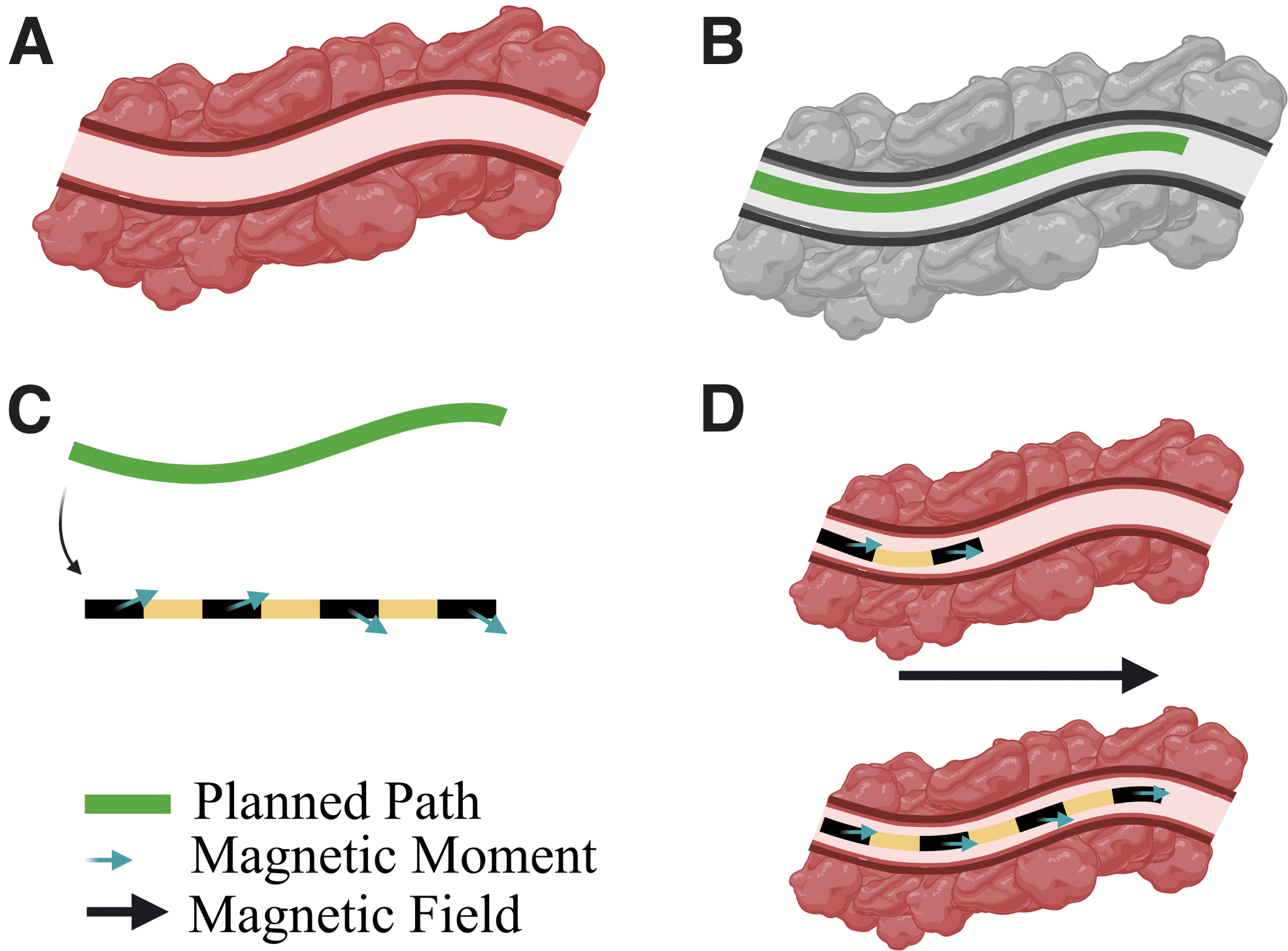
Magnetic signature optimization for follow-the-leader navigation. (
Electro-magnetic navigation (EMN) is a recently introduced image-based procedure with the goal of navigating a small catheter through the bronchial pathway of the lung up to the distal end of the bronchi. 15 In EMN, a passive catheter (rigid and prebent) is inserted into the tool channel of the bronchoscope and manually manipulated by using continuous electromagnetic feedback combined with pre- and/or intraoperative images.
The rigidity of the tool and its limited DOFs and proximal control make the procedure complex to perform, with reliance on catheter-tissue interactions and operator skill. Moreover, cone beam computed tomography (CT) or X-ray, used to visualize instrument location with respect to the lesion, is undesirable in terms of radiation exposure for both patient and medical staff, and it adds additional cost to the procedure. 12
Recent data found that EMN procedures had a diagnostic yield of only 57% over a total of 687 patients. 16 The difficulties in navigating the convoluted bronchial tree led researchers to investigate robotic solutions, such as the MONARCH® Platform and Ion Endoluminal System. These approaches have been introduced with the premise that better navigation and more accurate deployment of biopsy tools can improve the diagnostic yield. However, cable-driven robotic systems of this type comprise hard components with relatively large diameters: 4.2 mm (MONARCH; Auris Health, Inc.) and 3.5 mm (Ion; Intuitive Surgical). This makes them effective for navigation to the proximal anatomy, but deeper exploration must still be performed by using manual, stiff instruments.
In contrast, we show that our proposed 2 mm diameter patient-specific soft magnetic catheter can navigate autonomously, with the potential to penetrate deeper into areas of the anatomy inaccessible to standard instrumentation. The proposed catheter is the same diameter as the rigid tools used in EMN; however, it is also soft, anatomy-specific, fully shape-forming, and remotely robotically actuated. 15
We compare the proposed design approach with tip- and axially magnetized catheters and demonstrate improved navigation in terms of interaction with the environment and reduced targeting error. This is shown via two-dimensional (2D) navigation experiments where the shape of the catheter is tracked throughout the insertion process and the magnetic field is controlled by using the dual-robot-arm approach proposed by Pittiglio et al. 17 To demonstrate autonomous navigation in more realistic convoluted pathways, we evaluate our approach on an anatomically accurate 3D phantom of the bronchi extracted from a CT scan.
Materials and Methods
The high-level approach to realize shape-forming soft magnetic catheters under follow-the-leader control consists of: (1) determination of the desired navigational path (e.g., extraction from 3D image-based planning 18 ); (2) optimization of the lengthwise magnetic profile for the catheter and the magnetic control fields by using a magneto-elastic CR model; (3) fabrication of the magnetic catheter from soft elastomeric material with the desired optimized magnetic profile; and (4) synchronous control of the magnetic catheter insertion and the local magnetic field (in line with the optimization). The following sections detail the approaches taken to realize these specific elements.
Rigid-link modeling and design optimization
A popular approach for modeling elastomeric CRs is as a serial chain of spring-loaded rigid links.14,18 With sufficient links, such that no individual joint angle is large enough to violate the assumption of elastic linearity, an accurate representation of the CR when influenced by forces and torques is provided. One advantage of the rigid-link representation is the ease with which the CR fits into the traditional robotic manipulator Jacobian model. As shown in Figure 2, the rigid-link mechanical model and the magnetic torque equation for a current free field are employed within an optimization routine based on Lloyd et al.
14
Given a desired path (Fig. 2A), the optimization determines the lengthwise magnetization profile (
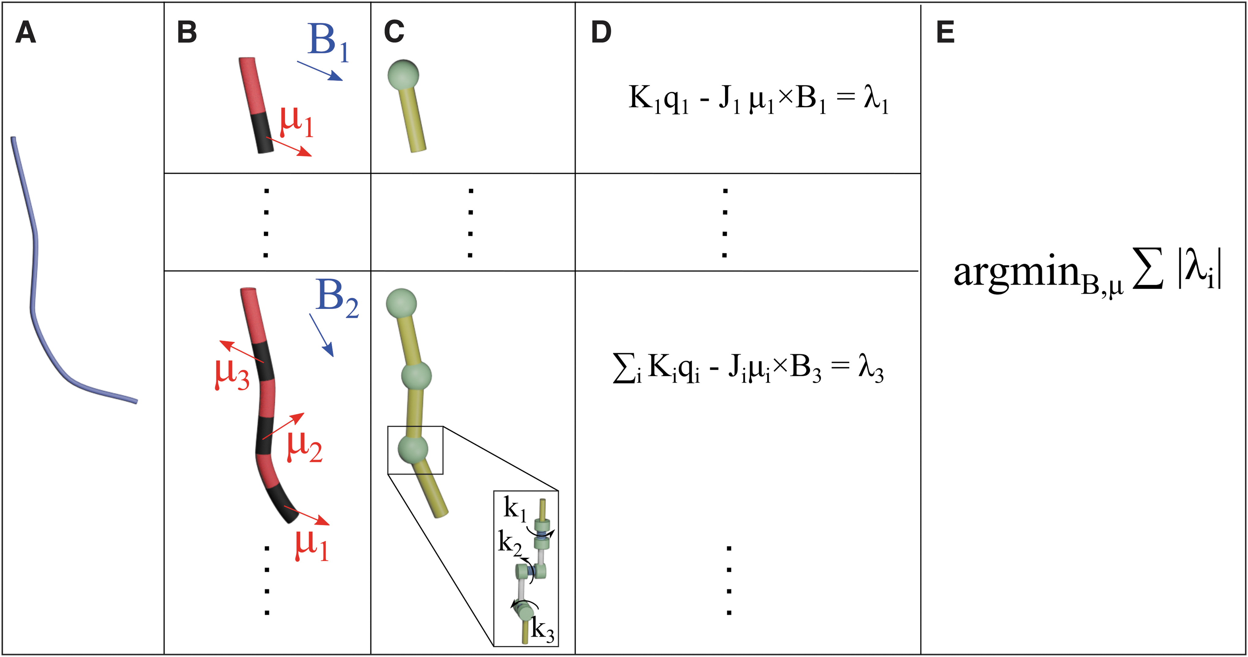
Building the optimization routine. (
For the presented examples, each catheter design is formed from multiple segments (Fig. 2B); each with its own magnetization direction and represented by a single rigid link (Fig. 2C). The mechanical joint torque is determined as the product of joint angle (qi) and pseudo-spring stiffness (ki). All joints are of the same geometry and material, meaning that the pseudo-spring constants (ki) used to represent mechanical resistance to beam deformation are uniform at every virtual joint.
As shown in Figure 2C, we modeled each manipulator joint as a serial chain of three joints representing rotation about each of three axes; the z joint manifests as the twisting primitive, and the y and x joints represent two orthogonal bending primitives. The pseudo-spring constants for each joint are given by
The magnetic joint torque is defined as the product of the manipulator Jacobian transpose (Ji) at any given time-step (i) and the magnetic wrench; it is determined as the cross-product of the magnetic moment (
Balancing the mechanical and magnetic wrenches gives, for a known set of joint angles, an open form solution with unknowns in magnetization and applied field. These are three-dimensional (3D) vectors at four locations (in the case of
Catheter fabrication
To produce the optimized catheter designs, individual magnetic segments were first fabricated with specific geometric and magnetic properties. Magnetic segments were formed by casting silicone prepolymer (Dragon Skin™ 30; Smooth-On, Inc.) mixed with magnetic microparticles (NdFeB, MQFP-B+; Magnequench GmnH, Germany) in a 3D-printed mold (Tough PLA; Ultimaker S5) (Fig. 3A). The two-part mold was assembled with the inclusion of two guide pins per segment (0.33 mm diameter Nitinol [NiTi] wire); it was inserted orthogonally to the long axis of the segments to act as indexing features for subsequent magnetization and assembly.

Fabrication process to produce SCMRs with specific magnetic signatures. Independent magnetic segments with indexing features are cast from silicone doped with magnetic microparticles (NdFeB) (
The silicone and magnetic particles, in a 1:1 ratio by mass, were mixed and degassed for 90 s in a high vacuum-mixer (ARV310; THINKYMIXER, Japan) followed by injection into the mold by using a standard syringe. The silicone was cured at room temperature for a minimum of 4 h before demolding. Once demolded and separated, each segment was magnetized by using an impulse magnetizer (IM-10-30; ASC Scientific). To induce the desired magnetic moment, as determined through the design optimization process, Figure 2, custom magnetizing trays were printed for each segment (Tough PLA; Ultimaker S5) with indexing pin holes to guarantee segment orientation with respect to the unidirectional magnetizing field (Fig. 3B).
Once all required magnetic segments were magnetized, they were assembled in appropriate order into a second two-part mold, using the indexing holes and pins to facilitate correct alignment and spacing during molding (Fig. 3C). Finally, silicone (Ecoflex™ 00-30; Smooth-On, Inc.) without magnetic particles was mixed, degassed, and injected into the mold to produce the complete catheter with a specific magnetic signature (Fig. 3D).
To generate locally invariant magnetic properties under actuation and improve conformation to the rigid-link model, magnetic segments (representing links) were formed from silicone with higher stiffness than the adjacent inter-segment “joints.” For 2D phantom tests reported next, an overall catheter diameter of 4 mm was used to improve image capture and data acquisition, whereas in the 3D anatomical model the overall diameter was reduced to 2 mm, which is our clinical target size. To improve contrast with the 3D anatomical model, red pigment (PM5 186 Sil Pig™; Smooth-On, Inc.) was added to the nonmagnetic silicone (0.1% by mass).
For 2D phantom tests reported next, four optimally magnetized catheters were fabricated (in addition to one each of tip- and axially magnetized control samples). For the 3D anatomical demonstration, a further three optimally magnetized catheters were fabricated.
Dual-arm magnetic manipulation
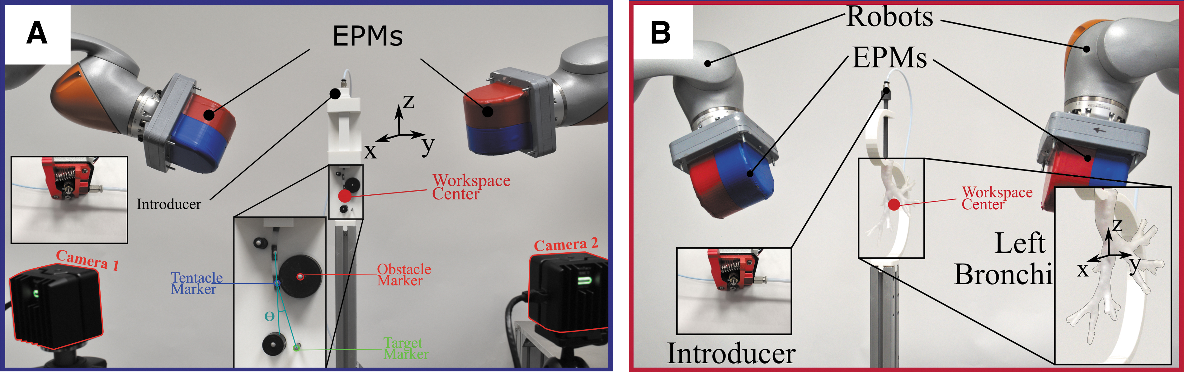
We apply the controlling magnetic field via the dual-robot-arm approach proposed by Pittiglio et al. 17 The aim of this dual external permanent magnet (dEPM) system (represented in Fig. 4) is to produce specific magnetic fields to generate torques on the magnetic segments of the catheter, as depicted in Figure 2D. Compared with a single permanent magnet,19–21 the dEPM system can produce gradient-free magnetic manipulation and, with respect to electromagnetic coil 2,3 systems, can more readily generate strong magnetic fields over a larger workspace.
(
Further, permanent magnets represent a more efficient solution than coils, since they provide higher magnetic flux density and do not require the supply of current to operate. However, this is at the expense of complexity, as coil systems can offer more intuitive control by current modulation.21,22
The design procedure is based on the assumption that the actuation method can generate a homogeneous field. Although the dEPM cannot generate the same field everywhere in the workspace, we can balance the gradient generated by one EPM with two opposing EPMs.
For safety purposes, we also restrict the position of the robots to be always on the opposite sides of the patient (Fig. 4). This ensures they do not collide with the patient or with each other. We can describe the actuation approach by using the dipole model:

where Bi is the field generated by the i-th EPM at position ri with respect to the center of the workspace,
Given the desired field

Notice that the norm of the magnetic moment
The robots are eventually controlled to the desired pose by kinematics inversion, depicted from the desired position ri and EPM magnetic moment mi. This control is synchronized with the actuation of the insertion of the catheter.
Notice that, in the center of the workspace, we can generate negligible gradients, whereas a single EPM would inherently generate field gradients. This guarantees a minimization of field inhomogeneity, which is an assumption of the proposed optimization approach.
2D experiments
To demonstrate the advantages of the proposed approach with respect to more simple catheter magnetizations, we performed two experiments: (1) a static (fixed length) obstacle avoidance example, and (2) three 2D navigation scenarios. For each experiment, three catheter designs were produced: (i) a catheter with only the distal segment magnetized in the axial direction—tip-magnetized, (ii) a catheter with all segments axially magnetized—axially-magnetized, and (iii) an optimized catheter with variable lengthwise magnetization—optimized.
The optimization technique detailed in Figure 3 was implemented in the same way for all three catheter designs. In the first two cases, the magnetization directions were constrained throughout the optimization to tip-segment axial and all-segments axial, respectively. Similarly, identical implementation of the algorithm to generate optimal actuating fields was employed for all cases. All catheter designs and controlling fields were, therefore optimized, with the goal of controlling the catheter shapes to the desired path as accurately as possible.
All catheters were fabricated with identical mechanical properties at a diameter of 4 mm to facilitate placement of 3 mm diameter position tracking markers. Three-dimensional tracking of the magnetic segments was performed by using an optical tracking system (OptiTrack; Natural Point, Inc.). Each 2D workspace and obstacle design was 3D printed (Tough PLA; Ultimaker), and additional tracking markers were located at each obstacle to act as reference points. Desired magnetic fields were generated by using the dEPM system in all cases. A representative example of the experimental setup is presented in Figure 4A.
For experiment (1), three catheter designs (i.e., tip-magnetized, axially-magnetized, and optimized) were actuated at a fixed length (i.e., 60 mm) to deform around a single circular obstacle. In each case, the maximum bending angle at the tip (with respect to a referential vertical position) was evaluated up to the point of contact with the obstacle. For the navigation experiment (2), we considered three scenarios with varied obstacle and target positions.
The choice of obstacle and target locations, and therefore catheter trajectories, was driven by both a practical constraint and a desire to demonstrate the multi-directional capacity of the optimization algorithm. The 2D demonstrative pathways were not based on anatomical images. These is a proof of concept in which obstacle and target locations were chosen to best demonstrate the multi-directional capacity of the optimization algorithm.
The resulting catheter trajectories are defined as those that give the maximum aggregate clearance from all the obstacles in the navigation while terminating at the target node. We selected trajectories that challenge our optimization procedure to accommodate multiple changes of direction in one navigation, that is, S-shaped deformation as opposed to C-shaped deformation. These convoluted routes represent a more rigorous test of shape-forming capacity and result in nonintuitive magnetizations and applied fields.
To facilitate insertion of the catheter designs, a bespoke introducer system was developed based on a Bowden cable mechanism (Fig. 4). A low-friction Bowden tube was connected between the drive mechanism and the test phantom by using threaded Bowden mounts. A 2 mm diameter filament was inserted through the Bowden tube and gripped at the proximal end between a drive gear and a spring-loaded idler bearing. A stepper motor (17HD34008-22B; Brusheng), coupled directly to the drive gear and controlled via a microcontroller (Arduino UNO; Arduino), was used to control the insertion length of the filament.
To connect each catheter design, the filament was extended beyond the distal end of the Bowden tube and the catheter design was reversibly coupled to the filament by using a 3D-printed pressure-fit coupling. The filament was subsequently retracted to the insertion start position for the catheter-test configuration (representing 0 mm displacement along the z axis). Subsequently, continuous insertion of the coupled filament and catheter was synchronized with the dEPM system and optical tracker to actuate and measure the catheter shapes respectively.
Anatomical phantom experiments
To demonstrate the proposed approach with realistic 3D anatomy, we extracted 3D pathways from a preoperative CT scan of the lungs from the Lung Image Database Consortium image collection (LIDC-IDRI-0807) (www.cancerimagingarchive.net). Full pathways were extracted from trachea to sub-segmental bronchi (diameter <4 mm); they were segmented from the CT data by using 3D Slicer (www.slicer.org). In contrast to standard EMN and robotic assisted bronchoscopy, we used preoperative imaging to design and fabricate patient-specific magnetic catheters to facilitate autonomous navigation via synchronized field-insertion control. Since the magnetic catheter is designed to shape autonomously to the predetermined path, the surgeon is completely relieved of the cognitive burden of navigation.
The procedure from image segmentation to design optimization is shown in Figure 4B. A section of the left bronchial tree, from left primary bronchus to subsegmental bronchi, was extracted from preoperative CT (Fig. 5A). Three independent 80 mm pathways of minimum diameter 2 mm were selected (Fig. 5B); optimization of the magnetization and control field for each was performed (as detailed in Fig. 2) to produce three path-specific catheters (Fig. 5C).

From a preoperative CT image to an optimized magnetic catheter.
A phantom corresponding to the isolated anatomical region was 3D printed in flexible resin (Flexible 80A, Form 2; Formlabs) and fixed in place within the dEPM robotic field control system by using a 3D-printed holder (Ultimaker Tough PLA, Ultimaker S5; Ultimaker) (Fig. 4). Before testing, the catheter was connected to the same introducer mechanism described in the previous section. In this case, the distal end of the introducer was coupled to a rigid 3D-printed insertion channel with an internal and external diameter of 3 and 6 mm, respectively (Fig. 4B).
This was designed to be comparable to the tool channel and outer diameter of standard bronchoscopes used for EMN (e.g., BF-1T180; Olympus Corporation). As in the 2D navigation case, forward motion of the catheter is actuated by step commands that run synchronously with the robot arms such that the catheter is inserted into the anatomy as the magnetic field is manipulated to the desired vector. The experimental setup detailed is shown in Figure 4.
To demonstrate successful navigation of the optimized catheters through the phantom, due to lack of an absolute measure, we performed a visual analysis of the videos. In fact, due to the opacity of the phantom, we could only visualize the catheter by transforming the video of the area of interest to black and white and increasing the contrast. This makes the catheter visible through most of the phantom (particularly in the narrower branches).
Results
2D obstacle avoidance
Results from the 2D obstacle avoidance experiment can be seen in Figure 6, where α represents the angle between the catheter tip in its actuated and unactuated (vertical) poses. It can be observed that larger deflection is possible before contact occurs in the optimized arrangement (Fig. 6C). Both tip and axially magnetized specimens (Fig. 6A, B respectively) impact the obstacle long before achieving the level of tip rotation attained by the optimized specimen. Under actuation, the tip and axially magnetized specimens can only achieve the large deflections shown by utilizing contact with the obstacle. The optimized specimen can be seen to deform through a larger angle while also avoiding obstacle contact. This is believed to facilitate navigation, since we can decouple the tip from full-body shaping, guaranteeing we can shape to the anatomy without inherent contact with it.
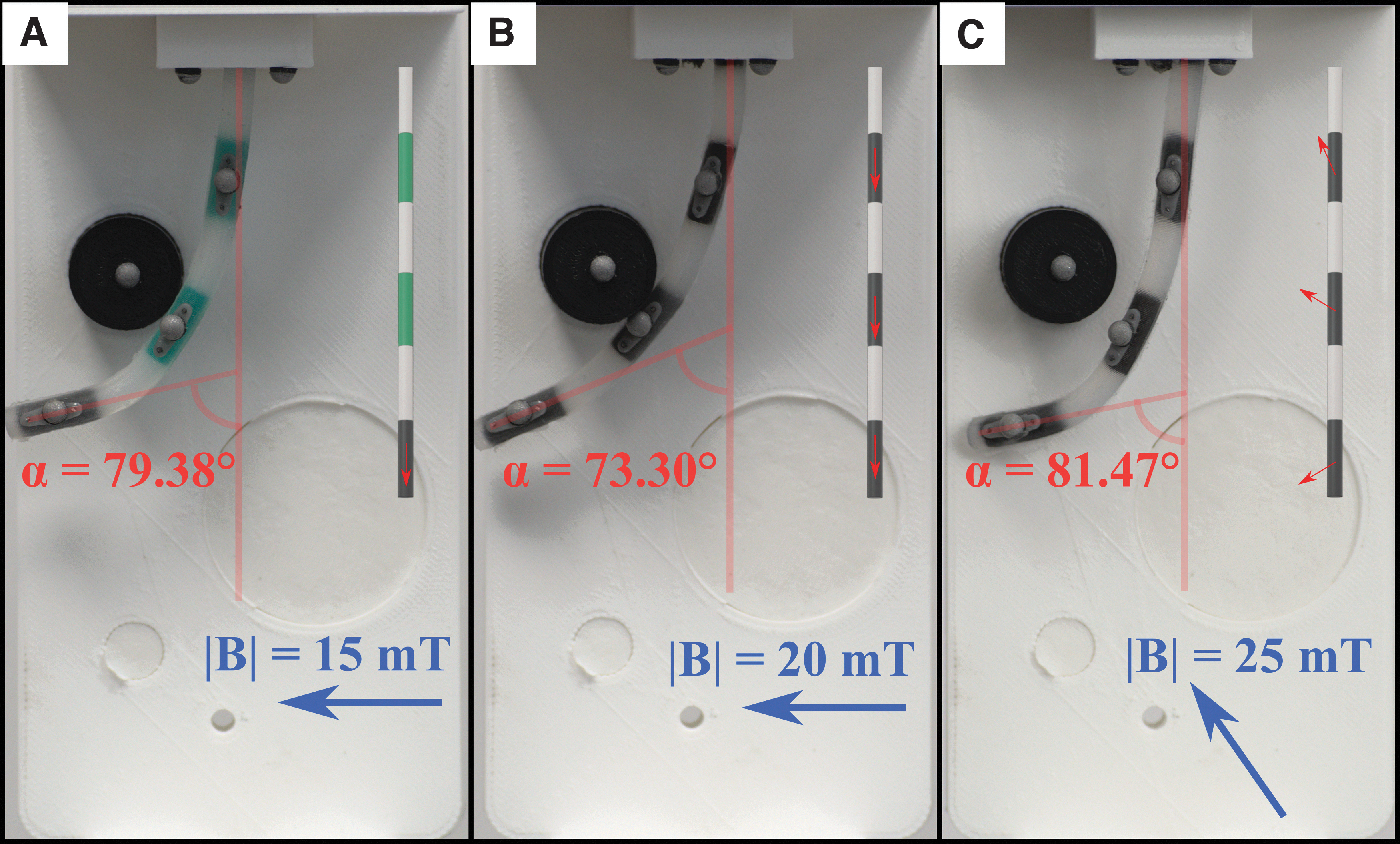
Results of obstacle avoidance experiments. Comparison of tip-magnetized (
These experiments are presented in Supplementary Video S1. It can be seen that, transitioning to the final state, the optimally magnetized catheter experiences some torsion around its main axis. This is particular to magnetic catheters whose magnetization is not purely axial. In some cases, this can cause undesirable behavior due to instabilities. The result from the obstacle avoidance presents a simplified and intuitive example of the optimized magnetic signature concept, which is expanded in the following sections.
2D navigation
Results are shown for three scenarios in which we report the shape of the catheter during navigation with tip magnetization, axial and finally with optimal magnetization (Figs. 7–9, respectively). Videos of the insertion processes for the three scenarios are shown in Supplementary Videos S2–S4, respectively. Also shown are the results of a finite element analysis that employed the Maxwell Stress Tensor to simulate the Magneto-Mechanical interaction.

Scenario A, comparison between the tip-magnetized (

Scenario B of comparison between the tip-magnetized (
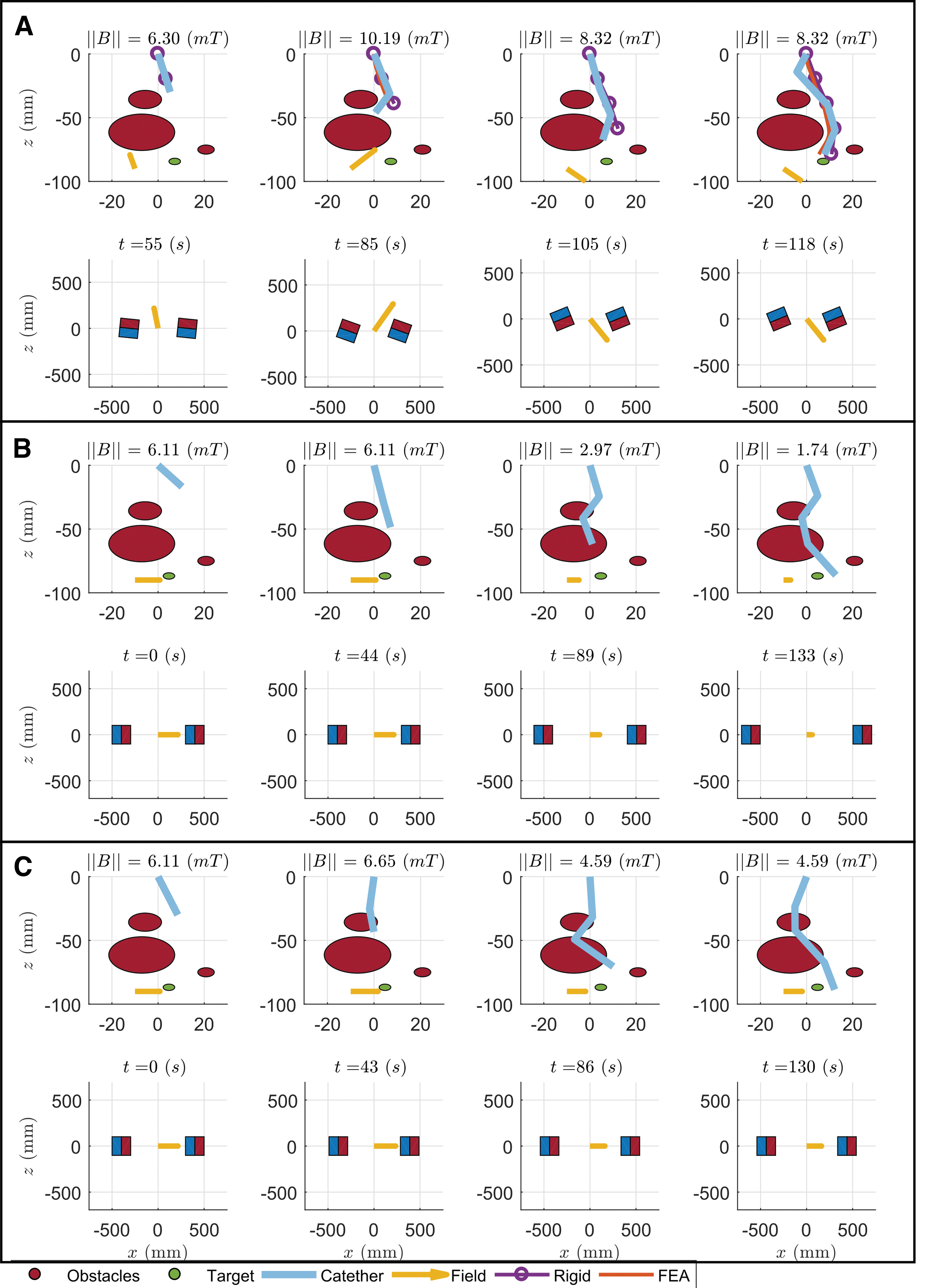
Scenario C of comparison between the tip-magnetized (
The tip- and axially magnetized catheters can be seen to not shape form to these convoluted trajectories. This, as shown in Figures 7, 8 and Supplementary Videos S2 and S3, leads to physical interaction with the surrounding environment, which compromises navigational capacity: that is, not reaching the target (e.g., Fig. 7A, tip magnetized). The tip-driven catheter interacts with the environment since its full shape cannot be controlled with any applied field. In Scenario A (Fig. 7), it cannot overcome the last obstacle since it is constrained by the penultimate obstacle and cannot shape around it.
Similar results are observed in Scenario B (Fig. 8). In Scenario C (Fig. 9), navigation to the target is achieved, since bending is not constrained. In all three scenarios, however, it cannot reach the target as accurately as the optimized catheter, due to interaction with the obstacles.
The axially magnetized catheter, despite interaction with the obstacles, is always able to reach the target. We hypothesize that this is due to the higher torque that can be applied to the overall catheter, compared with the tip-magnetized version. Nevertheless, environmental interaction is always present and hinders navigation capabilities. As obstacles are impacted, targeting abilities are adversely affected in comparison to the optimized approach; this is because tip position depends on the interaction of the full shape with the obstacles.
In contrast to the tip- and axially magnetized cases, we observe minimal interaction between the optimally designed catheter and the obstacles around that it is shaping across the three scenarios. The catheter can shape-form to the anatomy in a follow-the-leader fashion, as designated by the preoperative planning.
These results are summarized in Table 1, where the heading error Θ (defined in Fig. 4A), and obstacle contact time and tracking error are reported. The former is computed at the completion of each insertion (Scenarios A, B, C, in Figs. 7–9, respectively). The contact with the obstacles was computed by timing the contact between each obstacle and any section of the catheter from the Supplementary Videos. The overall results show that the optimal catheter can improve the navigation capabilities, by both reducing contact with the surrounding environment and achieving better targeting.
Summary of the Results of the Two-Dimensional Experiments
Heading error, contact time, and tracking error through each navigation. Indicated in boldfaced text the best of each trial and parameter.
For each insertion step, we compute the error between the optical marker(s)’ measured position and their desired position along the x axis. We compute the absolute value of the error, sum it through the insertion steps, and use it as a measure of the “Tracking Error” in Table 1. From this metric, we can see how tip- and axially magnetized catheters can follow the path by benefiting from the interaction with the environment, whereas the proposed design is always consistent regardless of the surroundings. In fact, in Scenario A the axially magnetized catheter's tracking error is comparable to the optimal catheter. However, in Scenarios B and C, where the environment provides less aid in shaping, the optimal design guarantees the desired shaping, whereas the others fail (Fig. 9 and the Supplementary Videos S1–S3).
In summary, the proposed design achieves contact minimization and, consequently, guarantees path following without the need for environmental interaction. This is fundamental in complex anatomical scenarios when the obstacles cannot provide the needed aid or, worse, they would prevent the catheter from following the desired path, forcing it to undesired shapes.
Anatomical phantom experiments
The selected routes were chosen to demonstrate navigation capabilities in diverse anatomical features that may be encountered in EMN. These pathways are commonly difficult to reach with standard bronchoscopy, due to their convoluted shapes. In Figure 10, we show the three anatomical experiments. Since the phantom is only partially transparent, we detail the shape of the catheter (red line), extracted by visual analysis.
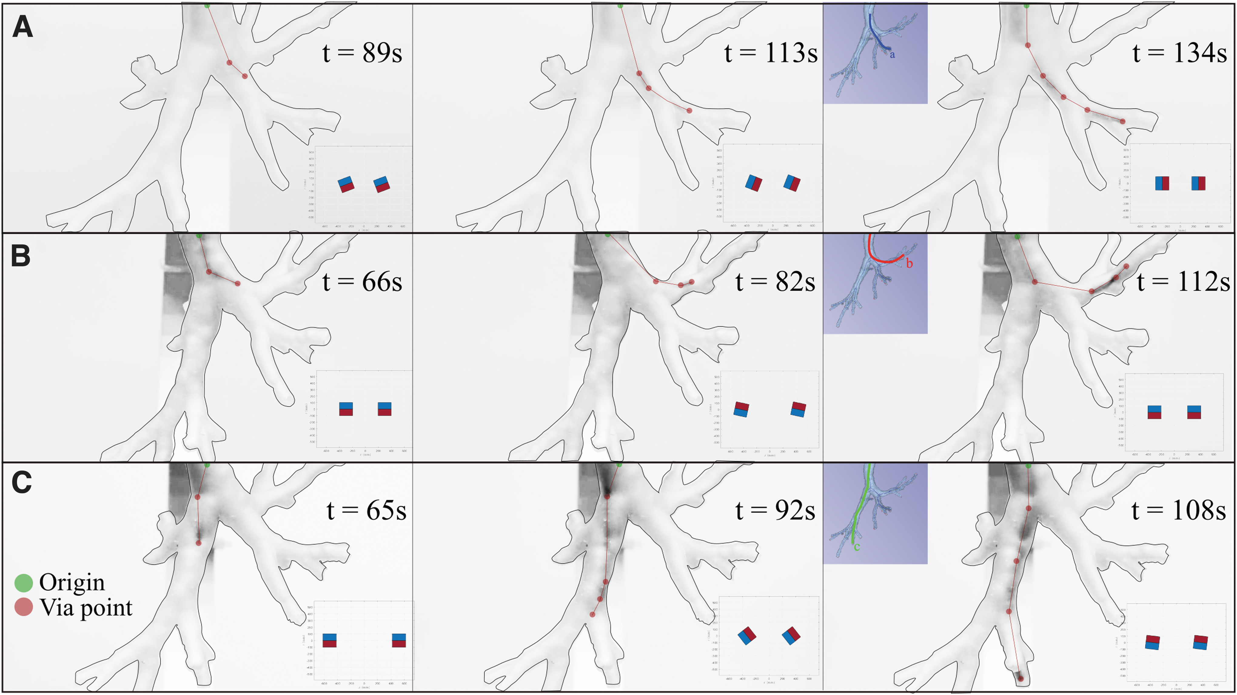
Demonstration of three 3D navigations: scenarios (
Specifically, we marked the via points (red dots), that is, the sections of the catheter visible from the black and white images and connected linearly with origin of insertion (green dot); this process was performed on a zoomed version of the images to enhance visibility. For additional information regarding these experiments, refer to Supplementary Video S5.
The results in Figure 10 show the ability of the fabricated catheter to autonomously shape to a convoluted anatomy. Three main distal ends of the left bronchi were successfully reached by manipulating the 3D field with the proposed actuation method on the optimally designed catheters. The autonomous shaping under the field applied by the dEPM is performed by design. In fact, shape-forming is completely defined by the design magnetization and applied field, informed by the preoperative CT, as discussed in the Methods section.
The case in Figure 10B shows that the catheter can achieve high levels of bending (almost 90°) and target hard-to-reach anatomical areas. This is achieved as a combination of high flexibility, small cross-section, high magnetic material concentration, and strong applied field. The three scenarios analyzed herein describe diversity in the anatomy, and successful navigation demonstrates that the proposed approach is applicable to a variety of anatomical conditions.
Discussion
The experiments performed show the advantages of using patient-specific magnetic catheters in endoscopy. We demonstrated improved shape-forming, obstacle avoidance, and targeting, compared with tip- and axially magnetized catheter designs. Specifically, we obtain 50% contact reduction and improved tracking, fundamental for both improving the navigation capabilities and reducing pain and discomfort for the patient. The reduced contact is also reflected in better tracking of the desired trajectory and targeting (90% improvement). In fact, in some cases, tip- and axially magnetized catheters may follow the trajectory since forced by the anatomy and fail in mitigating contact.
We also demonstrate how the proposed shape-forming catheters can navigate realistic anatomy, namely, a phantom of the bronchial tree derived from patient CT data. We selected three diverse anatomical features and showed successful navigation of the catheter in an open loop in around 2 min, for all cases.
This work is based on preoperative planning and open-loop control. In real clinical scenarios, we may not guarantee feasible navigation without tracking of the catheter and the anatomy online. Therefore, we will consider intraoperative imaging (e.g., X-ray) and shape sensing of the catheters to guarantee navigation via closed-loop control.
In our experimental analysis in the bronchial tree, we employed a constrained dEPM platform to guarantee an EPM-EPM distance of 50 cm, which can fit an average patient. However, we do not exclude the potential need for larger permanent magnets in clinical application, to account for any possible patient size.
The optimized catheters were designed with a planar magnetization and proven effective in the scenarios proposed. The discussed optimization and actuation can deal with nonplanar magnetization, but the current fabrication method may fail in creating out-of-plane magnetic dipoles. We will develop a more appropriate fabrication method, which we expect to further improve navigation and reduce contact with the environment.
The optimized catheters are inherently characterized by a nonaxial magnetization, which we proved to facilitate navigation. However, this may also lead to undesired torsion, as seen in some experiments. This behavior is mainly due to the applied gradient-free actuation, which may cause instabilities. We will consider the usage of gradients, already discussed by Pittiglio et al., 17 to control the torsion of the designed catheters. In case the torsional behavior is undesired, we will also integrate optimization constraints and/or mechanical constraints, as discussed by Lloyd et al. 22
Conclusions
In this work, we have introduced a novel design approach for patient-specific, magnetically driven, shape-forming soft catheters. The goal of the approach is to design and fabricate catheters to navigate the human body with minimal and atraumatic environmental interaction, thus facilitating enhanced navigation and targeting ability while reducing postoperative recovery time. The use of preoperative imaging in the design paradigm ensures the catheter follows the anatomical pathway while being subject to an omni-directional controlled magnetic field.
We demonstrate that the proposed approach can perform less invasive navigation and more accurate targeting, compared with previously proposed magnetic catheterization techniques. Moreover, we describe and demonstrate the full process of preoperative path planning, design optimization, and navigation in bronchoscopy. We present the capabilities of the proposed catheters in an anatomically accurate 3D bronchi phantom by exploring three diverse branches.
Experiments were performed in a static environment to demonstrate the accuracy of the proposed design technique. To achieve full autonomy, as demonstrated for colonoscopy in Martin et al., 23 and for further reduction of intraoperative imaging, future work will address closed-loop control of both catheter location and shape.
Further, future research will aim at controlling magnetic field gradients and, thus, magnetic force during navigation; target torsion reduction via both design/fabrication and control approaches; and integration with diagnostic or therapeutic instruments ( for e.g., biopsy). These developments will be in concert with further miniaturization, automated fabrication, and the addition of friction reduction strategies. Through the presented patient-specific magnetic catheter approach, we believe that atraumatic autonomous exploration of a wide range of anatomical features will be possible, with the potential to reduce trauma and improve diagnostic yield.
Footnotes
Authors’ Contributions
G.P. and P.L. used the model and optimization technique, and they performed experiments and writing. G.P. developed the actuation method for magnetic field control and catheter insertion. J.C. developed the fabrication technique, with contribution from T.d.V., supervised the experiments and writing. O.O. helped in the setup of the 2D experiments. C.P. helped in the clinical relevance of the work. P.V. supervised the work from technical and writing aspects and provided support to the research.
Disclaimer
Any opinions, findings, conclusions, or recommendations expressed in this article are those of the authors and do not necessarily reflect the views of the Garfield Weston Foundation, EPSRC, or the ERC.
Author Disclosure Statement
No competing financial interests exist.
Funding Information
The research reported in this article was supported by the Garfield Weston Foundation, by the Engineering and Physical Sciences Research Council (EPSRC) under grants number EP/R045291/1 and EP/V009818/1, and by the European Research Council (ERC) under the European Union's Horizon 2020 research and innovation program (Grant Agreement No. 818045).
References
Supplementary Material
Please find the following supplemental material available below.
For Open Access articles published under a Creative Commons License, all supplemental material carries the same license as the article it is associated with.
For non-Open Access articles published, all supplemental material carries a non-exclusive license, and permission requests for re-use of supplemental material or any part of supplemental material shall be sent directly to the copyright owner as specified in the copyright notice associated with the article.