
Abstract
This study presents a multimaterial topology optimization method for design of multimaterial compliant mechanisms. Traditionally, the objective function in topology optimization for design of structures is to minimize the strain energy (SE). For synthesis of compliant mechanisms, the objective function is usually to maximize the mutual potential energy (MPE). To design an adaptive compliant gripper for grasping size-varied objects, a multicriteria objective function considering both the SE and MPE at two different output ports is proposed in this study. In addition, based on the fact that different infill densities in three-dimensional (3D) printing leads to prototypes with different equivalent mechanical properties, this article proposes that a multimaterial design can be approximated by varying the values of infill densities in different portions of a 3D-printed component, which enables the multimaterial designs to be prototyped using the general low-cost, single-material fused deposition modeling 3D printing machines. The proposed method is used to design and prototype a bi-material compliant finger which is 3D printed using a flexible thermoplastic elastomer with infill densities of 30% and 100%. The experimental results demonstrate that the bi-material finger is a better design in terms of reducing the driving force while increasing the output displacement at the fingertip comparing to the single-material finger design with the same volume and weight. Furthermore, a two-finger gripper with two identical multimaterial-like compliant fingers is prototyped and installed on a six-axis industrial robot. The experimental tests are performed to demonstrate the effectiveness of the presented design.
Introduction
Robots can be classified as hard or soft on the basis of the compliance of their underlying materials. 1 Generally, materials with elastic moduli in the order of 104–109 Pa are considered to be soft materials. 2 Soft and compliant robotic systems generally have the potential to handle unexpected interactions with unstructured environments or humans in more sophisticated ways than rigid robots.3,4
Recent advances in soft robotics, material science, and stretchable electronics have enabled rapid progress in developing soft grippers. 5 As an end-effector is the only interface between the robot and the working environment, the overall performance of a robot highly depends on its end-effector design. 6 Soft grippers are usually with two, three, or four fingers that can be actuated by motors7–11 or pneumatic pumps.12–15 Elastomeric materials such as silicon rubbers,7,13,15–17 thermoplastic polyurethanes, 10 rubber-like resins,12,14 vulcanized rubbers,18,19 and thermoplastic elastomers (TPEs)8,9,11,20 are often used in prototyping soft grippers.
Recent fused deposition modeling (FDM) three-dimensional (3D) printing technology allows users to print soft materials, such as TPEs, with prespecified infill densities (or infill percentages). A TPE is one kind of soft flexible filament that has the processability of thermoplastics and the elasticity of vulcanized rubber. 21 A higher infill density in 3D printing leads to higher strength and higher mass in the printed components. 22 An infill density of 100% is equivalent to a solid print.
Since current multimaterial 3D printers are more expensive comparing to the general single-material 3D printers, a multimaterial design can be approximated by varying the values of infill densities in different portions of a 3D-printed component based on the fact that different infill densities in 3D printing leads to prototypes with different equivalent mechanical properties, which enable the multimaterial designs to be prototyped using the general low-cost FDM 3D printers.
Topology optimization is a numerical method to optimize the material layout within a given design domain and is one major approach to synthesize compliant mechanisms.23–29 Unlike traditional rigid body mechanisms, compliant mechanisms transform the displacement and force at least partly through the deformation of their structural components, which can offer a great reduction in friction, lubrication, and assemblage. 29
The algorithms of topology optimization methods are extensively investigated in the literature over the past several decades29–33 and have been used in developing various soft robotic grippers.8–11,14,16,17,20,34–37 For example, Wang et al. 10 developed a cable-driven two-finger soft gripper with multiple input ports; a topology optimization method is used to synthesize the compliant finger considering multiple working conditions. A three-finger cable-driven soft robotic gripper presented by Chen et al. 35 is prototyped with a 3D-printed TPE and can be used to grip objects up to 1 kg.
Topology optimization methods are also used in design of pneumatic soft grippers. For example, Zhang et al. 14 developed a topology optimized 3D-printed soft pneumatic finger; experimental results show that each finger is able to undergo a 14.7° free travel bending and exert 0.23 N grasping force upon 60 kPa actuation pressure. A three-finger multimaterial pneumatic soft robotic gripper presented by Zhang et al. 36 can grip objects with dimension ranging from 4 to 80 mm and a weight from 2.4 to 167.9 g.
The authors' group has developed several motor-driven adaptive soft grippers8,9,11,16,17,20 through various topology optimization algorithms. The working principle for the designs is to provide a displacement input at the input port of the gripper; then the fingers bend elastically to generate the gripping motion. Our first design 16 is a monolithic two-fingered compliant gripper where each finger is divided into two segments with different objective functions during topology optimization. The design objective for the fingertip structure is to minimize compliance to firmly grip the object, whereas the objective for another finger segment is to maximize output displacement to drive the finger for enclosing an object.
Another monolithic two-fingered design 17 aims to maximize the mechanical advantage of the compliant gripper. Both grippers16,17 are initially synthesized using a topology optimization step; then, a geometry optimization step is further used to update the detailed geometric parameters while maximizing the geometric advantage 16 and mechanical advantage, 17 respectively.
To account for objects with larger size without increasing the finger dimensions, a rigid-flexible integrated gripper module that uses a motor-driven translational moving platform to drive two individual compliant fingers mounted on a fixed platform is presented 8 ; in addition, a strain energy (SE) based objective function capable to synthesize compliant mechanisms with two output ports is proposed to synthesize the compliant finger. Different numerical parameters and boundary conditions are used to design the 3D-printed compliant fingers.9,11 The numerical results show that the recent finger design 11 is with a lower driving force and a lower maximum equivalent stress during operation comparing to the previous design. 8
To regulate the maximum output force, an absorber-type constant-force mechanism 20 is developed and installed on an electric gripper drive to provide passive force control and overload protection during gripping operation; the numerical computation in Ref. 20 is treated as an error minimization problem between the output and objective forces within a desired input displacement range while updating the density variables to obtain an optimal material layout during topology optimization.
One possible improvement direction for our previous studies8,9,11,16,17,20 is to consider multimaterial problem in topology optimization as our previous designs8,9,11,16,17,20 involve only single-material formulations.
Although the topology optimization method has been used to design a multimaterial soft pneumatic finger by Zhang et al., 36 their formulations for topology optimization actually consider only single-material condition as they separate their finger design into inner layer (softer material) and outer layer (harder material); the inner layer is preserved unaltered, while the outer layer is reshaped during the topology optimization process.
Zuo and Saitou 38 present an ordered multimaterial interpolation scheme to solve multimaterial topology optimization problems without introducing any new material density variables. In this approach, 38 power functions with scaling and translation coefficients are introduced to interpolate the elastic modulus and the cost properties for multiple materials with respect to the normalized density variables. But the discontinuity of the interpolation derivatives and the checkerboard pattern problem are two possible issues for this approach that can be further investigated.
Gaynor et al. 26 present a combinatorial topology optimization approach to design a manufacturable multimaterial compliant inverter mechanism with the design objective of maximizing the output displacement. The presented three-phase compliant inverter refers to a design with void, stiff, and compliant phases (i.e., a bi-material design), and each phase contributes to the elastic modulus for an element. In addition, their experimental results 26 show that the maximum deflection of the bi-material compliant inverter can be increased by as much as 84% by comparing to the single-material compliant inverter, which demonstrates that a multimaterial design could achieve a better performance than a single-material design as it has a larger design freedom.
Motivated by the need to develop a topology optimization method that can consider the multimaterial condition using multiple material density variables for design of a compliant finger for grasping application, this study presents a multimaterial topology optimization method and a multicriteria objective function to design a multimaterial compliant gripper. Based on the fact that different infill densities in 3D printing lead to the prototypes with different equivalent mechanical properties, the topology-optimized multimaterial gripper design can be made by varying the values of infill densities in different portions of a 3D-printed compliant finger. The optimal design of a bi-material compliant finger is obtained using the proposed method. The multimaterial design is prototyped with the TPE material with different infill densities, and experimental results are provided in this study.
Multimaterial Topology Optimization Method
The flowchart of the proposed multimaterial topology optimization method is shown in Figure 1. The optimization problem starts from the definition of design domain, boundary conditions, parameters, and design variables. A density filter 39 is used to prevent the appearance of checkerboard patterns and mesh dependency problems. A robust topology optimization formulation considering erosion, intermediate, and dilation projections40,41 is used to avoid the generation of hinges in the synthesized compliant mechanisms after topology optimization. A multimaterial formulation and a multicriteria objective function are proposed in this study. The method of moving asymptotes 42 is used to update the design variables until convergence.
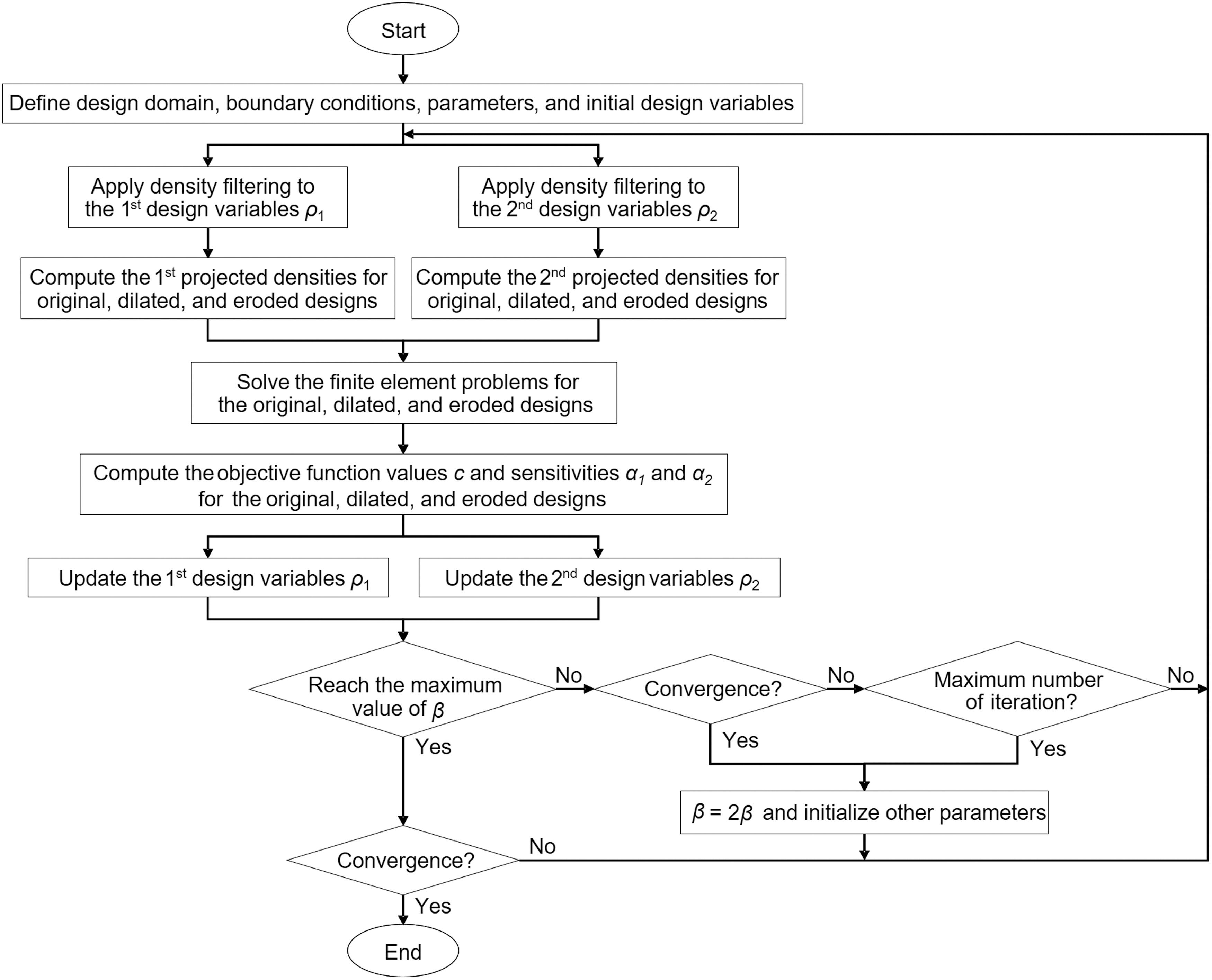
Flowchart of the proposed multimaterial topology optimization method.
Based on the density filter,
39
the filtered element density (
where Ne, i is the neighborhood set of elements lying within the filtering domain of the ith element, wij is the weighting function, vj is the volume of each element,
Furthermore, a projection scheme
40
is used in this study to obtain a black-and-white solution (minimize the existence of gray elements) after topology optimization. The projected element density is formulated as
where
The projection scheme transfers the filtered element density into the projected element density. Figure 2 shows the effect of the projection parameter β and the threshold value η on the value of the projected element density. The filtered element density is the value before the projection, whereas the projected element density is the value after the projection. The threshold values in Figure 2a–c are defined as 0.3, 0.5, and 0.7, respectively. From Figure 2, it can be noticed that a larger value of β leads to a clear 0 or 1 projected element density after the projection, while the threshold density is determined by the threshold value η.

The effect of the projection parameter β and the threshold value η on the value of the projected element density. The filtered element density is the value before the projection, whereas the projected element density is the value after the projection.
In this study, the value of the projection parameter β is gradually increased from 1 to 512 to gradually transfer the filtered element densities during the iterations to ensure a black-and-white solution after topology optimization. The update strategy of the projection parameter β is shown in Figure 1.
Based on the concept of the solid isotropic material with penalization,
39
the elastic modulus of an element for a traditional single-material topology optimization problem can be written as
where Ei is the elastic modulus of the ith element, E0 is the elastic modulus of the original material, Emin is the minimum elastic modulus (which is a small positive value close to zero), p is the penalty parameter, and
For a bi-material topology optimization problem, the Equation in (3) can be reformulated as
where E1 is the elastic modulus of material 1, E2 is the elastic modulus of material 2,
A robust topology optimization formulation based on erosion, intermediate, and dilation projections40,41 is used to ensure an optimized material layout while considering the manufacturing tolerance. Typical topology optimization problems only deal with the original intermediate design, while the robust topology optimization method also considers the eroded and dilated designs which could cause manufacturing uncertainties. The eroded design refers to an overcut condition in physical prototyping that results in a size-decreasing feature on the prototype, while the dilated design refers to an undercut condition that results in a size-increasing feature.
The design problem is formulated as a min-max problem among the three different designs (the eroded design, the original intermediate design, and the dilated design) which can be obtained by adjusting the threshold value in the projection function in Equation (2). The threshold value of the original intermediate design is set to 0.5, while the threshold values of the eroded design and the dilated design are defined as 0.7 and 0.3, respectively, in this study. The optimization problem is to minimize the objective function for the worst case of the eroded, intermediate, and dilated designs.
For a bi-material condition, the optimization problem can be formulated as
where c is the objective function of the optimization problem that consists of the eroded, intermediate, and dilated designs40,41; the design with a maximum objective function value will be selected to be minimized;
To design an adaptive compliant gripper for grasping size-varied objects, this study presents a multicriteria objective function combining mutual potential energy (MPE) and SE. In addition, the target design of the compliant finger considers two output ports, which are at the fingertip (output port #1) and the midpoint of the gripping jaw (output port #2), respectively, as illustrated in Figure 3. The objective function for the optimization problem is formulated as

Analysis domain of the compliant finger.
where c is the objective function to be minimized; ω is a weighting factor; MPE and SE in Equation (6) are defined as
In addition
where
The sensitivity for the objective function with respect to the element density can be calculated by
where c is the objective function as defined in Equation (6);
As the objective function is a combination of the MPE and SE, we can first evaluate the derivative of MPE with respect to the projected element density.
The derivatives of the first two equations in Equation (9) with respect to the projected element density are
Substituting Equation (12) into Equation (11) yields
For a single element
where
where
The derivative of the MPE with respect to the first projected density of the ith element can be obtained by substituting Equations (4) and (15) into Equation (14), which yields

Similarly, the derivative of MPE with respect to the second projected density of the ith element can be obtained as
Next, the derivative of the SE with respect to the projected element density can be written as
The derivative of the third equation in Equation (9) with respect to the projected element density is
Substituting Equation (19) into Equation (18) yields
For a single element
where
By substituting Equations (4) and (15) into Equation (21) yields the derivative of the SE with respect to the first projected density.
Similarly, the derivative of the SE with respect to the second projected density can be obtained as
Based on the results from Equations (16) and (22), the sensitivity for the objective function in Equation (6) with respect to the first projected element density can be written as
Based on the results from Equations (17) and (23), the sensitivity for the objective function in Equation (6) with respect to the second projected element density can be written as
By substituting Equation (24) into Equation (10) yields the first sensitivity of the optimization problem, which is the gradient value of the objective function with respect to the first design variable ρ1.
Similarly, by substituting Equation (25) into Equation (10) yields the second sensitivity of the optimization problem, which is the gradient value of the objective function with respect to the second design variable ρ2.
The sensitivities in Equations (26) and (27) are both used for the eroded, intermediate, and dilated designs (that are with different values of η); the design with a maximum objective function value will be selected to be minimized as in Equation (5).
Material Parameters for the 3D-Printed TPE Specimens with Different Infill Densities
The commercial TPE filament, Filastic™, made by BotFeeder is used in this study to prototype the multimaterial-like compliant finger. Based on the fact that different infill densities in 3D printing leads to the prototypes with different equivalent mechanical properties, a multimaterial design can be approximated by varying the values of infill densities in 3D printing of a component, which allows the multimaterial designs to be manufactured using the general low-cost FDM 3D printers. The 3D printing slicing software, Simplify3D, is used in this study. The infill pattern in 3D printing is defined as rectilinear. The manufacturing parameters in 3D printing include nozzle diameter = 0.4 mm, primary layer height = 0.2 mm, perimeter shell = 1, primary extruder temperature = 220°C, heated bed temperature = 40°C, and printing speed = 30 mm/s.
The experimentally measured material parameters for the 3D-printed TPE specimens at different infill percentages, including 100%, 70%, 60%, 50%, 40%, and 30%, are summarized in Table 1. Tensile tests are performed to obtain the engineering stress-engineering strain curves. The experimental data within the engineering strains from 0 to 0.1 are used to linearly fit the equivalent elastic modulus. The equivalent densities are calculated by the measured mass and volume values. Both the values of equivalent elastic modulus and the equivalent density are increased when the value of infill percentage increases. A linear trend line can be used to represent the equivalent density in terms of the value of the infill percentage, while the relationship between the equivalent elastic modulus and the infill percentage can be curve fitted by a third degree polynomial, which yields
Measured Material Parameters for the Three-Dimensional-Printed Thermoplastic Elastomer Specimens with Different Infill Densities
The experimental data within the engineering strains from 0 to 0.1 are used to linearly fit the equivalent elastic modulus.

where Eeqv is the equivalent elastic modulus with a unit of MPa, and ρinfill is the infill percentage. The relation in Equation (28) can be used to estimate the equivalent elastic modulus for an infill percentage between 30% and 100% for the analyzed TPE.
In this study, the TPEs with infill percentages of 100% and 30% are used in topology optimization and prototype of the bi-material finger design, whereas the TPE with infill percentage of 50% is used for the single-material design for the purpose of comparison.
Topology Optimization of the Multimaterial Compliant Finger
The discussed multimaterial topology optimization procedure given in Figure 1 is used to synthesize a bi-material compliant finger. As denoted in Figure 3, the analysis domain for the compliant finger consists of a design domain with an irregular pentagon shape, a triangular void nondesign domain, and a rectangular solid nondesign domain. The solid nondesign domain is the expected contact region between the finger and the gripped objects. The elements in the solid nondesign domain are defined as the solid elements, whereas the elements in the void nondesign domain are defined as the void elements. The element densities for the elements in the design domain can be varied from 0 to 1 by a small increment.
The analysis domain corresponds to a gripper driving module that consists of a linear stage and a fixed stage for mounting the compliant fingers. The input port as denoted in Figure 3 corresponds to the linear stage of the driving module, whereas the fixed port corresponds to the fixed stage. The target design for each finger of the compliant gripper considers two output ports; the output port #1 as denoted in Figure 3 is at the fingertip, whereas the output port #2 is at the midpoint of the gripper jaw.
Maximizing the MPE at output port #1 allows the gripper to maximize the output displacement at the fingertip, while minimizing the SE at output port #2 enables the gripper to resist the external load at the midpoint of the gripper jaw when grasping objects. The weighting factor ω in Equation (6) is defined as 0.1, which implies that the major design objective of the finger is to maximize the MPE at the fingertip while partially minimizing the SE at the midpoint of the gripping jaw. The dummy input force f1, dummy output force f2, and dummy reaction force f3 are specified at the input and output ports, respectively. The numerical parameters used in topology optimization are summarized in Table 2.
Parameters for Topology Optimization
Both the single-material design and the bi-material design of the compliant finger are identified in this study. As summarized in Table 1, the elastic modulus for the single-material design is 14.19 MPa, which corresponds to the 3D-printed TPE with a 50% infill density. In addition, the elastic moduli for the bi-material design are 42.82 and 10.29 MPa, which correspond to the 3D-printed TPE with infill densities of 100% and 30%, respectively.
The topology optimization results for both the single-material design and the bi-material design are shown in Figure 4, where the x-axis represents the iteration number, and the y-axis represents the objective function value. Both the single-material design and the bi-material design are with the same values of volume and weight. The objective function value for the single-material design as shown in Figure 4a is converged to −2.5671 after 263 iterations, whereas the objective function value for the bi-material design as shown in Figure 4b is converged to −2.6660 after 307 iterations. The objective function value for the bi-material design can be slightly improved by 3.9% comparing to the single-material design.
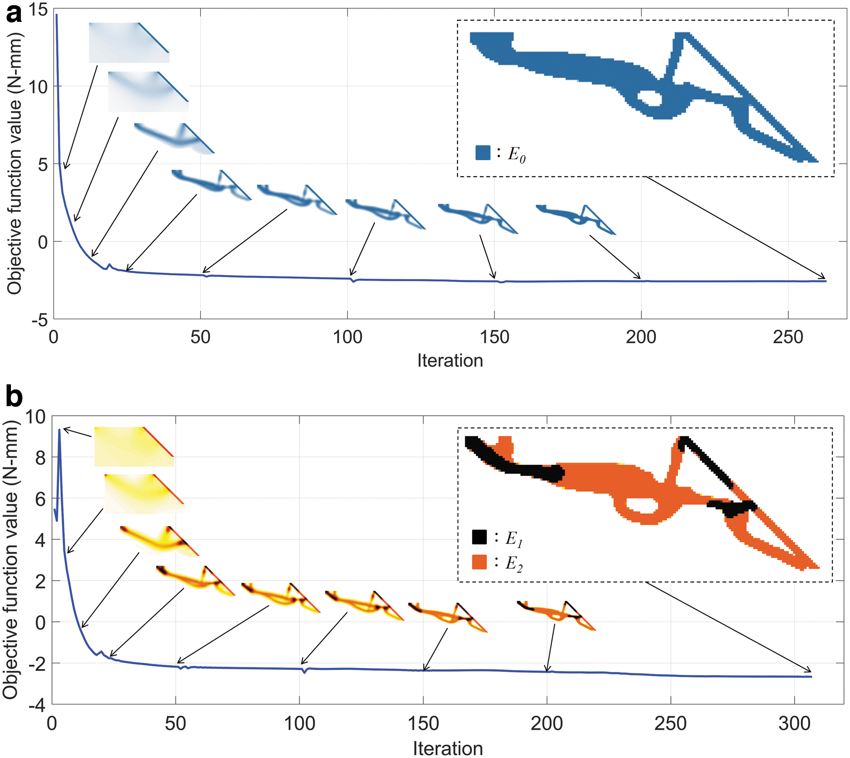
Topology optimization results for the compliant finger.
Prototypes and Experimental Results
A Prusa i3 FDM 3D printer with the commercial TPE filament, Filastic, made by BotFeeder is used to print the compliant fingers shown in Figure 4. Figure 5 shows the prototypes of the 3D-printed compliant fingers. Both fingers are with a thickness of 20 mm. The single-material design as shown in Figure 5a is printed with the infill density of 50%, whereas the bi-material design as shown in Figure 5b is printed with the infill densities of 30% and 100%. Both designs are with the same values of volume and weight.

3D-printed compliant fingers.
The experimental setup to measure the input force and output displacement values corresponding to the amount of input displacement of both fingers is shown in Figure 6. The fixed port of the compliant finger is placed on a fixed stage through a pin joint, while its input port is mounted on a linear stage. The input displacement is applied at the input port of the tested finger that can slide along two steel rods through the linear stage. A force gauge, Lutron FG-6020SD, is used to measure the required input force of the tested finger. The output displacement at the fingertip is estimated through image processing.

Experimental setup for measuring the input force and output displacement values correspond to the amount of input displacement.
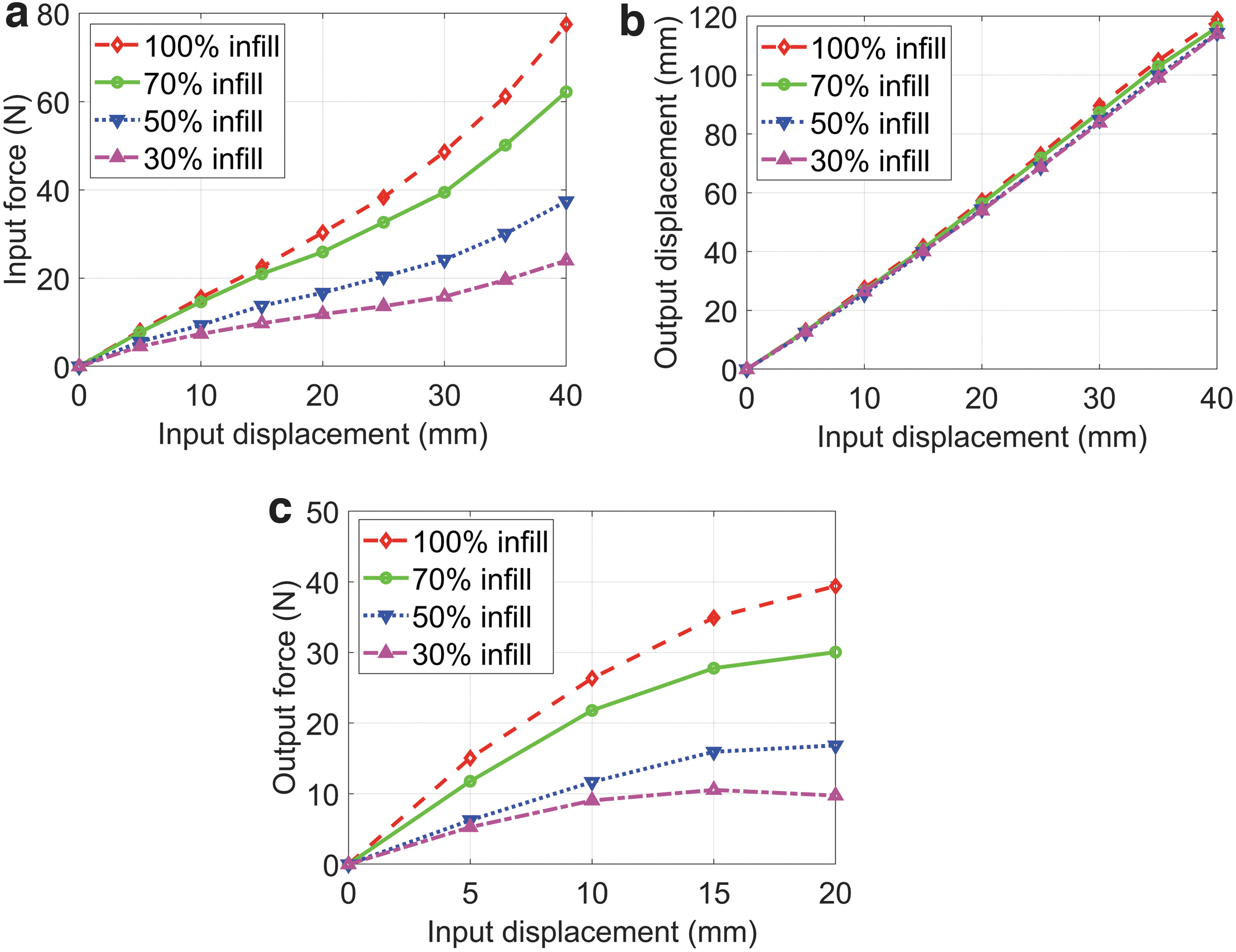
Figure 7a shows the measured input displacement versus input force curves for the single-material and the bi-material-like fingers. From Figure 7a, it shows that the required input force of the bi-material-like finger is smaller than the single-material finger. The amount of the input force for the bi-material design can be reduced from 8.3% to 28% at different amounts of the displacement input. The average force reduction rate is 20% within the input displacements ranging from 5 to 40 mm at 5 mm increments. The relationship between the input force and the input displacement is not linear due to the geometric nonlinearity under large deformation condition.

Measured force and displacement values correspond to the amount of input displacement.
Figure 7b shows the measured input displacement versus output displacement curves for the single-material and the bi-material-like fingers. From Figure 7b, it shows that the amount of output displacement for the bi-material design can be increased from 10% to 17% at different amounts of the displacement input, while the average displacement increment is 12% by comparing to the single-material design. In addition, two previous finger designs8,11 as shown in Figure 7b are prototyped with the infill density of 50% and tested using the same experimental setup as shown in Figure 6 to measure the output displacements at their fingertips; the measured results are also provided in Figure 7b for the purpose of comparison.
It can be observed that both the single-material and the bi-material-like fingers presented in this study outperform the previous designs8,11 in increasing the output displacement (i.e., the output speed). The amount of output displacement for the bi-material design can be increased from 48% to 78% at different amounts of the displacement input, while the average displacement increment is 59% by comparing to the previous design in Ref. 8 By comparing to the finger design in Ref., 11 the amount of output displacement for the bi-material design can be increased from 51% to 105% at different amounts of the displacement input while the average displacement increment is 73%.
The results in Figure 7a and b demonstrate that the bi-material-like finger in Figure 5b is a better design in terms of reducing the driving force while increasing the output displacement at the fingertip by comparing to the single-material finger design in Figure 5a that is with the same volume and weight as the bi-material design. As the design objective presented in this study is primarily to maximize the MPE at the fingertip while partially minimizing the SE at the midpoint of the gripping jaw, the amounts of the output displacement for both finger designs presented in this study are significantly larger than the previous designs8,11 since maximizing the MPE at the fingertip corresponds to maximizing its output displacement under the same input force.
Figure 7c shows the measured input displacement versus output force curves for the single-material and bi-material designs, as well as the two previous finger designs.8,11 The experimental setup for measuring the output force is similar to the setup given in Figure 6 except that the force gauge is placed (and fixed) at the output port of the compliant finger to measure the output force. According to the design scheme in Figure 3, the output port #2 is used to measure the output force for both the single-material and the bi-material designs, whereas the fingertip is used for the output force measurement for the two previous designs8,11 based on their original design schemes.
From Figure 7c, it can be observed that the output force values for the bi-material design are larger than the single-material design by 26% and 11%, respectively, at the input displacement of 5 and 10 mm. As the single-axis force gauge is initially normally in contact with the finger, the force reading becomes inaccurate for the bi-material design when the input displacement is increased beyond 10 mm as the contact orientation changes significantly. In addition, since the design objective presented in this study is mainly equivalent to maximizing the output displacement at the fingertip, the output force of the bi-material design is smaller than the previous design in Ref. 11 as the major design objective of the previous finger in Ref. 11 is equivalent to maximizing the output force.
To investigate the effect of infill density on the input force, output displacement, and output force for the developed single-material finger (with an infill density of 50%), three additional fingers with the infill densities of 30%, 70%, and 100% are prototyped and tested in this study. Figure 8a shows the measured input displacement versus input force curves. It can be observed that a higher input force is required for the prototype with a higher infill percentage. Figure 8b shows the measured input displacement versus output displacement curves. The results show that a higher infill percentage of the finger can lead to a slightly larger value of the output displacement. Figure 8c shows the measured input displacement versus output force curves. The results show that a higher infill percentage of the finger leads to a higher output force.
Effects of the infill density on the measured input force, output displacement, and output force of the single-material design.
The prototype of the proposed two-finger compliant gripper is shown in Figure 9, where Figure 9a and b shows the open mode and close mode, respectively, of the two-finger gripper. The initial opening distance between the two fingertips is 142 mm as denoted in Figure 9a. The overall weight of the two-finger gripper is around 0.8 kg.

The prototype of the soft gripper with the bi-material-like compliant fingers.
The soft gripper consists of one driving module and two identical bi-material-like compliant fingers. The driving module is a compact version of the previous design. 8 The input port for each finger is mounted on a linear stage of the driving module, whereas the fixed port of each finger is mounted on the bottom fixed stage. One stepper motor (Oriental Motor PKP235D23A) is used to drive the linear stage through the timing belt pulley set and one threaded rod. When the linear stage moves toward the fixed stage, both fingers bend elastically to generate the gripping motion as shown in Figure 9b.
The experimental results show that an input displacement stroke of 40 mm can be completed in 4 s so that the input speed of the developed gripper is around 10 mm/s, while the output speed for each bi-material-like finger at the fingertip is around 30 mm/s, which is faster than the previous finger designs8,11 by around 48%.
The payload test result is given in Figure 9c. The experiment is carried out iteratively by gradually increasing the weight of the mass blocks in the tray hanging on the gripped object. The maximum payload is estimated as 2.4 kg for the developed gripper with two bi-material-like compliant fingers. To demonstrate the effectiveness of the developed two-finger gripper, a variety of objects, including a steel block, a steel cylinder, a hard disk drive, a gear, a tomato, a raw egg, a glass cup, and a curved glass cup, are used as the target objects in the grasping test. The experimental results are given in Figure 10, which show that the two-finger compliant gripper can be used for handling of these size-varied and delicate objects.

Grasping test results of the soft gripper with the bi-material-like compliant fingers.
Conclusions
A multimaterial topology optimization method for synthesis of multimaterial compliant mechanisms is presented in this article. A multicriteria objective function considering the MPE and SE at two different output ports is proposed, and the sensitivity analysis results for the proposed multicriteria objective function with respect to the element density are derived in this study. The proposed method is used to synthesize a bi-material compliant finger. The target design for each finger of the compliant gripper considers two output ports, which are located at the fingertip and the midpoint of the gripping jaw. Maximizing the MPE at the fingertip allows the gripper to maximize the output displacement (i.e., the output speed) for enclosing an object, while minimizing the SE at the midpoint of the gripping jaw enables the gripper to resist the external load that is exerted by the gripped object.
The experimentally measured material parameters for the 3D-printed TPE specimens at different infill densities, including 100%, 70%, 60%, 50%, 40%, and 30%, are summarized in this article. In addition, based on the fact that different infill densities in 3D printing lead to prototypes with different equivalent mechanical properties, the identified multimaterial finger design is prototyped by varying the values of infill densities in different portions of the 3D-printed compliant finger using a general single-material FDM 3D printer.
The optimized single-material finger design is printed with the infill density of 50%, whereas the bi-material finger design is printed with the infill densities of 30% and 100%. The experimental results demonstrate that the bi-material finger is a better design in terms of reducing the driving force while increasing the output displacement at the fingertip comparing to the single-material finger design with the same values of volume and weight. The amount of the input force for the bi-material design can be reduced by 20% in average, while the amount of output displacement can be increased by 12% in average within the input displacement stroke at 5 mm increments.
The results demonstrate that the multimaterial topology optimization method and bi-material design presented in this study can achieve a better performance than the single-material design as it has a larger design freedom in exploring an optimum solution. To investigate the effect of infill density on the input force, output displacement, and output force of the developed single-material design, the compliant fingers with the infill densities of 30%, 50%, 70%, and 100% are prototyped and tested. The experimental results show that a higher infill percentage of the finger leads to a higher input force, a slightly larger output displacement, and a higher output force.
In addition, the soft gripper with two identical multimaterial-like, 3D-printed compliant fingers is prototyped and installed on a six-axis industrial robot to perform the grasping tests. The experimental results show that the two-finger compliant gripper can be used for handling of size-varied and delicate objects. The overall weight of the two-finger gripper is around 0.8 kg, and its maximum payload is estimated as 2.4 kg. As the maximum payload is affected by the friction and the contact region between the gripper and an object, the estimated maximum payload may vary for different objects with different materials, sizes, shapes, and surface conditions.
Footnotes
Author Disclosure Statement
No competing financial interests exist.
Funding Information
This work was supported by the grant, MOST 110-2628-E-006-004, from the Ministry of Science and Technology of Taiwan.