
Abstract
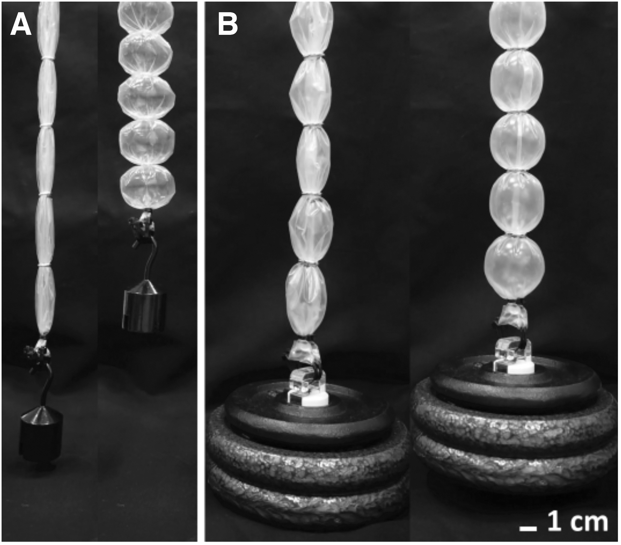
Soft robotics requires new actuators and artificial muscles that are lighter, less expensive, and more effective than current technologies. Recently developed bubble artificial muscles (BAMs) are lightweight, flexible, inexpensive, pneumatic actuators with the capability of being scalable, contracting at a low pressure, and generating sufficient tension and contraction for assisting human mobility. The BAMs are simply fabricated by using a commercial plastic tubing with retaining rings, forming a “bubble” shape and creating a series of contractile units to attain a desired stroke. They can deliver high contraction through optimization of actuator length and radius, or high tension by strengthening their materials to operate at high pressure. Here, we present a detailed analysis of BAMs, define a model for their actuation, and verify the model through a series of experiments with fabricated BAM actuators. In tests, a maximum contraction of 43.1% and a maximum stress of 0.894 MPa were achieved, corresponding to the BAM lifting a load 1000 times its own weight (5.39 g). The BAM model was built to predict experimental performance, for example, the relationship between tension and contraction at various applied pressures, and between contraction and pressure. Characteristic analysis and design optimization of the BAM are presented as an approach to design and manufacture the ideal “bubble” actuator at any required dimensions. A BAM orthosis is demonstrated as assisting a sit-to-stand transition on a leg mechanism, constructed to match the scale of a human's lower limb. Guidelines for further improvement of the BAM are also included.
Introduction
Assistive technologies have emerged to endow humans with more capabilities and independence in life, especially among older adults. Powered exoskeletons and orthoses have considerably developed over the past decades to provide wearers with more strength and mobility. 1 These rigid exoskeletons can be divided into two categories based on their purposes: (1) enabling and restoring mobility in patients with disabilities and (2) strengthening workers and soldiers to undertake heavy activities for industrial or military applications. 2 However, there are many ongoing challenges and requirements, including low weight, flexibility, comfort and adaptability to human body, esthetics, affordability, long lifetime, reliability, and safety. In addition, restriction of natural body motion and damage to the body of healthy individuals must be avoided.
Soft robots have advantages over conventional rigid robots thanks to their light weight and compliance, being more suitable for direct interactions with the human body while potentially reducing harm. Pneumatic artificial muscles (PAMs) are one of the most commonly used actuators to drive assistive soft exoskeletons. 3 Although pneumatic exoskeletons were initially made of mostly rigid components,4,5 more recently they have been developed with more flexible, compliant elements.6–15 Soft exoskeletons and artificial muscles have also used a range of power sources, including cable-tendon-driven mechanisms, that is, Exosuit, 16 Myosuit, 17 and XoSoft 18 ; direct electro-mechanical energy transduction in polymers, for example, polyvinyl chloride (PVC) gel,19,20 dielectric elastomers,21,22 dielectrophoretic liquid zipping actuators, 23 and Peano-HASEL 24 ; and thermo-mechanical actuation such as coiled polymer. 25
PAMs are soft, flexible contractile actuators that change shape and contract when activated by pressurized air. 26 The McKibben pneumatic muscle is widely used in soft exoskeletons. It is made of a length of an elastic tubing enclosed by a braided sleeve, which contracts to form a cylindrical shape under an applied pressure. 27 Similarly, straight fiber PAMs use an elastic tube featuring reinforced fibers to increase membrane strength, and they form a spherical shape when actuated.28–31
Other soft pneumatic actuators (SPAs) apply this concept of using a stiff embedded sheet on the inside of soft elastomer 32 or creating a three-dimensional (3D)-printed soft contractile actuator consisting of stiff and soft composites. 33 These PAMs use an elastic material as the actuator's membrane, which stretches and expands under high applied pressure, and use a stiffer material to limit membrane expansion, resulting in a pre-determined shape and contraction.
On the other hand, pleated pneumatic artificial muscles (PPAMs) only use a high-strength inelastic material as an actuator membrane constrained by special end fittings to create equal radial pleats at the actuator ends, contracting to an elliptical shape under pressure. 34 The PPAMs were initially used as an artificial muscle for a gripper, a robot arm, and a walking or running mechanism. 35 Pouch motors use a commercial flexible plastic material to create a lightweight series contractile actuator, allowing low-pressure actuation. 36 Bending SPAs, made of a thin-walled flexible tubing, have achieved large bending motions and high torque at low pressure operation. 37 These three actuators benefit from their inelastic material's strength to operate under pressure and produce contraction and tensile force.
Recently, new contractile PAMs made of a commercial inelastic plastic tubing with the addition of soft rubber rings (series pneumatic artificial muscle—sPAM) or rigid metal rings (bubble artificial muscles—BAMs) have been presented. The sPAM 38 was developed for navigation and survey applications, enabling a low-pressure soft continuum robot to steer and operate in constrained and cluttered environments, 39 whereas the BAM was developed as a human-like muscle to assist human mobility, for example, for aiding knee flexion during walking. 40
The BAMs are lightweight, compliant, and inexpensive pneumatic muscles, designed to have similar structure and function as the PPAM while being considerably simpler, less expensive, and lower weight; being made of a thin, flexible inelastic tubing and stiff retaining rings. This grants the BAM flexibility and low- to high-pressure actuation to deliver either high contraction or high tensile force depending on the thickness and stiffness of the tubing material (Fig. 1; Supplementary Movie S1).
Actuation of BAMs.
The BAM can be designed to deliver the most suitable mechanical assistance for different parts of the human body, which requires different tensile forces and amounts of contraction. To enable this design flexibility, we present characteristic analysis and design optimization of BAMs, develop an actuator model encompassing the unique buckled folds at the rings, and verify the model against experimentation with a range of BAM actuators.
Pneumatic Actuators
Pleated pneumatic artificial muscle
We first consider the PPAM
34
(Supplementary Fig. S1A), from which models of the sPAM and the BAM are derived. The characteristics of the PPAM are based on actuator length L, actuator radius R, and applied pressure P, with the assumption of inelastic material behavior. The PPAM mathematical model was derived by using an elliptical integral with m and φR as dominant parameters to determine the actuator shape at any contraction. Three main equations are used to calculate the contraction c and tensile force T of the PPAM, as follows:
m defines the actuator's shape and its contraction, where zero contraction or maximum contraction are reached when m is equal to 0 or 0.5, respectively (
Series pneumatic artificial muscle
The sPAM is made of a long plastic tubing and rubber O-rings, creating a series of pneumatic actuators similar to the PPAM. 38 Unlike the PPAM, an inactive region appears in the sPAM when the actuator length of the sPAM is greater than a certain value. This occurs when the actuator radius reaches the maximum material radius (the radius of the plastic tubing used to build the sPAM), causing the actuator to form a cylindrical region in the middle of the actuator, preventing the generation of further contraction, and thus limiting the overall contraction ratio. Although each contractile unit of the sPAM generates high contraction close to that of the PPAM model, it produces much lower tensile force than the PPAM due to its low material strength, which limits applied pressure.
Bubble artificial muscle
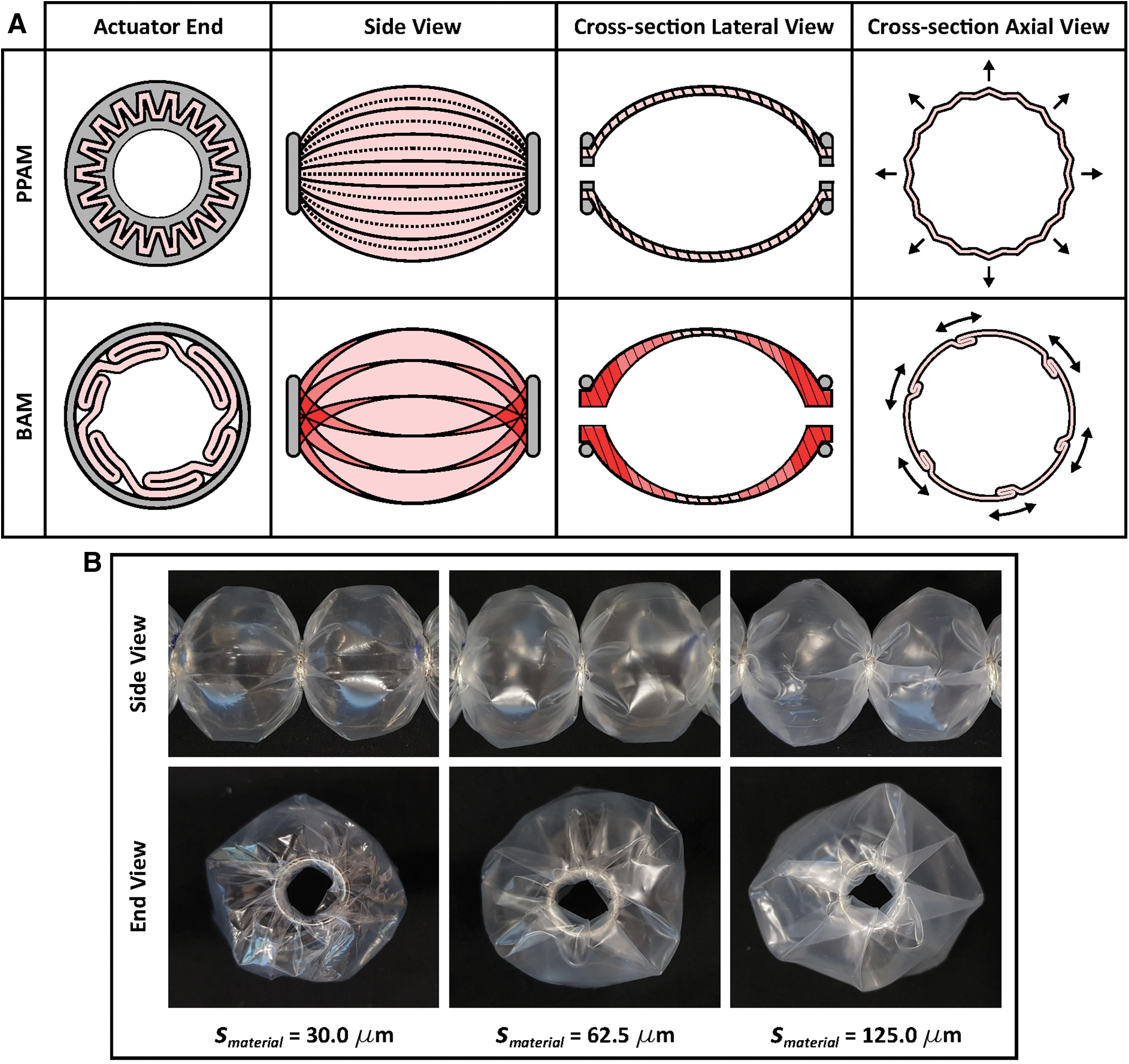
The BAM was developed to deliver high tensile force while maintaining high contraction. This is achieved by introducing stiff retaining rings and strong actuator material, allowing the BAM to sustain high pressure. The BAM is made by using a polyethene plastic tubing and metal retaining rings (Fig. 2A). Two metal rings (gray in Fig. 2A) are inserted along the plastic tubing (pink in Fig. 2A) to create a single contractile unit. These metal rings constrain the tubing to form a tight folded shape within the ring radius (cross-section AA in Fig. 2A). Non-uniform folding of the plastic tubing extends along the actuator in the axial direction (red dashed lines in Fig. 2A). These induced folds function similarly to the pleats in the PPAM. The result is a PAM that is considerably less expensive and easier to manufacture compared with the PPAM, while exhibiting higher tensile force compared with the sPAM.

When inflating the BAM by pressurized air, the actuator membrane unfolds and expands radially, and thus the actuator contracts, forming different expanded shapes, that is, a vertical elliptical shape, a circular shape, and a horizontal elliptical shape, depending on the level of applied pressure P (Fig. 2B). Increasing the applied pressure results in an increase in actuator contraction. This increase happens only in the inelastic phase, whereby the membrane flexes and the actuator changes shape, with negligible elastic stretching of the membrane. If the pressure is increased beyond the point of maximum contraction, behavior enters an elastic phase.
In the inelastic phase (Fig. 2B), increasing the applied pressure causes the actuator membrane to stretch, inflating like a balloon, which results in a decrease in contraction. The optimal contraction happens when the actuator forms a horizontal elliptical shape in the inelastic phase, which resembles a “bubble,” leading to the name of the actuator, “Bubble Artificial Muscle.”
As shown in Figure 2A, the BAM is fabricated from a plastic tubing with a maximum material radius
The optimal contraction
A fold length
Besides the optimal BAM, other expanded shapes can be obtained at the maximum applied pressure, depending on
The BAMs are designed to produce sufficiently high force and contraction to drive an orthotic to assist human muscles. As described earlier, BAM characteristics depend on an initial unit length
Experimental Setup
Several experiments were conducted to investigate the effects of P,
To evaluate the BAM performance, two types of experiments were undertaken: an isometric test and an isotonic test. For isometric testing, the BAM was oriented vertically, with the top end mounted on an acrylic frame connected to a 1 kN load cell (700 Series S Beam Load Cell; Load Cell Shop, UK) and the bottom end attached to a linear actuator (LACT8P; Concentric International, USA). The tensile force was measured by the load cell through a load cell amplifier (RW-ST01A; SMOWO, China), and the actuator stroke was controlled by the linear actuator and recorded by a laser displacement sensor (LK-G152; Keyence, Japan). Pressurized air was supplied by an air compressor (CW 100/24 AL; Werther International S.p.A., Germany) connected to the actuator through a pressure regulator (AR20-F02H010B; SMC, UK) and a solenoid valve (WZ-98302-46; Cole-Parmer, UK), which were used to regulate the pressure level and inflate and deflate the actuator. A pressure sensor (HSCDANN030PGAA5; Honeywell, USA) was located close to the actuator to measure the applied pressure.
For isotonic testing, the bottom end of the actuator was disconnected from the linear actuator and a test mass was hung instead. The rest of the test environment was identical to the isometric test.
All tested BAMs consisted of four contractile units, excluding the optimal-unit-length experiment. Isometric tests were used to investigate the effects of varying P,
Results
Increasing applied pressure (P)
A BAM with

This result can be explained by the progression from the inelastic phase to elastic phase, as presented in Figure 2B. Increasing applied pressure over a certain threshold (between 30 and 40 kPa in this case) causes the actuator membrane to stretch (behavior enters the elastic phase) and results in a reduction in the maximum contraction. Further increasing pressure would lead to irrecoverable plastic deformation and ultimately rupturing, therefore experiments were halted when elastic behavior occurred, before rupture. This stretching behavior can occur at any contraction when exceeding the pressure threshold (Supplementary Fig. S3A).
Varying initial unit length (
)
Five BAMs with
As shown in Figure 3C, the greatest maximum contraction occurs at
Varying ring radius (
)
A BAM with constant
From Figure 3D, decreasing
Optimal unit length (
)
The effects of the overlapped region and the inactive region, which influence
The largest contraction (mean at 36.9% and maximum at 38.7%) was observed for the BAM with
Varying material thickness (
)
Isotonic and isometric tests were performed to evaluate the BAM's capability to produce contraction with an external load of 1 kg and maximum tensile force at

Contraction and tensile force of BAMs (Lunit = 40.5 mm and Rring = 4.5 mm) with three different smaterial undergoing
Overall, at the same applied pressure, BAMs with thicker membranes produce less contraction and generally less tensile force, deviating increasingly from the PPAM model prediction (Fig. 4A). From Figure 4B, the tensile force of each BAM tends to decrease due to stretching behavior when applied pressure approaches their maximum pressure; increasing applied pressure further can cause the BAM to burst. The results of the isometric test measuring tensile force of the three BAMs at strokes other than zero are shown in Supplementary Figure S4.
Further isometric tests were performed to obtain the relationship between tensile force and contraction of BAMs with different

Figure 5B shows the effect of decreasing
As can be seen in Figure 5B, discrepancy between the PPAM and sPAM models is maximized at high
Discussion
BAM performance
Typical pneumatic actuators can deliver a maximum contraction of around 25–35%, for example, McKibben muscle and Pouch Motor.26,36 Since the maximum expanded shape of the PPAM, sPAM, and BAM actuators is the horizontal ellipse (Fig. 2B), they can all feasibly reach a maximum contraction of 45.5% (Ref.
35
). A single-contractile-unit PPAM with
Compared with these PAMs, the BAM can be designed to deliver either high contraction when using the thinnest
Similarly, a BAM with
Comparison between PPAM, sPAM, and BAM
Although the BAM superficially resembles the PPAM, they have different fundamental structures due to different actuator ends: a special end fitting for the PPAM and a metal ring for the BAM (Fig. 6A). The PPAM has uniform pleats in the radial direction, whereas the folds of the BAM are in the lateral direction. These lateral folds are freely and nonuniformly folded around the metal ring, creating a region of overlapping folds, which naturally resists the radial expansion of the BAM. As membrane thickness increases, the amount of lateral folds also increases (Fig. 6B), increasing resistance to BAM shape expansion and reducing contraction and tension. However, higher thickness materials can withstand higher applied pressures, leading to higher expanding force and thus higher tensile force and maximum contraction of the BAM when loaded (Fig. 4).
When the BAM is inflated, the folds unfold by sliding and bending to expand the actuator shape (Fig. 6A), approaching the circular actuator cross-section (CC in Fig. 2C). The thickness of the folded membrane along the actuator axis x may be defined as the bubble surface thickness
Although the sPAM and BAM share some functionality, the sPAM was designed to control the movement of lightweight continuum robots. In contrast, the BAM was designed as a high-power artificial muscle (e.g., for wearable assistive applications), necessitating higher contraction and tension. Various aspects of the BAM design result from these higher required performance metrics (high-thickness plastic tubing that allows for considerably higher applied pressure, metal retaining rings that withstand high radial force and folding analysis).
An isotonic test using a load of 1 kg demonstrates the difference in performance between these two actuators (Supplementary Fig. S6). With the BAM, the metal rings maintained an effective actuator shape, resulting in the BAM contraction after theoretical PPAM contraction. In contrast, the rubber rings of the sPAM stretched as applied pressure was increased, inducing an inactive region and causing large deviation from the PPAM model. Maximum BAM contraction was 26.5% at 40 kPa, significantly larger than the sPAM contraction of 18.2% at the same pressure.
BAM characterization
The BAM introduces new behavior, an overlapped region, which, together with the inactive region present in the sPAM (Fig. 2D), reduces maximum contraction and causes deviation from the PPAM mathematical model. The overlapped region occurs when there is a large amount of folds around the actuator ends, causing crossover of the folds from two ends and overlapped membrane across the actuator. It increases the membrane stiffness and difficulty in unfolding and bending of the folded membrane, and it reduces the bubble radius
When fixing

The BAM parameter (top row), the predicted PPAM shape (middle row), and the actual BAM shape (bottom row) at maximum shape expansion when
Likewise, the overlapped region and the inactive region occur when varying
Although the inactive region can be addressed by decreasing
BAM actuation model
Although the BAM produces lower performance than the PPAM theoretical maximum (Figs. 4 and 5) because of the fundamental difference in their folding structure, they share the same ideal behavior of shape expansion (Fig. 2B). Consequently, the BAM mathematical model is built on the PPAM model with the addition of the inactive region modeled by the sPAM model, and modifications to model the effects of material thickness (Supplementary Figs. S7 and S8). The PPAM and sPAM models overestimate BAM performance in terms of contraction and tensile force, as they do not account for material thickness, a major factor in BAM actuation. This deviation can be reduced by modifying the inelastic PPAM model with an additional term based on experimental observation. The effect of the inactive region from the sPAM model, which can limit the maximum contraction, is also included in the BAM model.
As described earlier in the Varying Material Thickness (
The relationship between tensile force and contraction of the BAM (Fig. 5A) can be modified from the PPAM model by using the subtractive contraction loss
The comparison between the PPAM model, the sPAM model, the modified model for the BAM, and the experimental data of the BAM (

In contrast, the relationship between contraction and pressure (Fig. 4A) is better modeled by applying a multiplicative tension loss,
Design optimization
Analysis summarized in Figure 9 shows how the BAM actuator differs from the PPAM and the sPAM, and how it can be optimized to achieve high contraction by choosing three ratios of material properties:

Model-predicted maximum contraction of
Figure 9B shows the maximum contraction predicted by the sPAM model. At any
BAM improvement
The performance of the BAM can be improved by several approaches. First, better quality fabrication and a method for creating uniformly lateral folding along the actuator are required so that the BAM can unfold and expand more easily with lower friction. Uniform folding can increase BAM contraction and decrease the deviation between the mathematical model and the practical performance.
For the current design, the rings are placed without any attachments to the tubing. After repeated actuation, the rings tend to be fixed in place by the shape adopted by the folded membrane; as
Last, using high-strength inelastic materials, the BAM can operate under higher applied pressure to deliver higher tensile force. The ideal actuator membrane should possess high Young's Modulus and extremely high tensile strength to withstand high pressure for high tensile force, have low interfacial friction, and be very thin and very flexible to expand easily at low-pressure actuation and deliver high contraction.
BAM Orthosis for Sit-to-Stand Transition
A leg mechanism was built to evaluate the BAM performance in assisting human mobility in the task of standing up from a sitting position (sit-to-stand), as shown in Figure 10A. It consists of three segments: a foot base, a shank rod, and a thigh rod, which are connected via revolute joints representing the knee and ankle (Fig. 10B). It was designed so that the shank rod can be fixed at an adjustable ankle angle and an external load can be added to the hip joint, to represent a body weight. A BAM orthosis was created by using three pairs of BAMs aligned in parallel (Fig. 10D). In each pair, BAMs are connected in series by cables and located at the thigh and shank at 7.5 cm from the center axis, labeled as BAM1 and BAM2, respectively (Fig. 10C).

The experimental setup of the sit-to-stand motion
Each BAM contains seven contractile units, where
Conclusion
The BAM is one of the most lightweight pneumatic actuators (<6 g) that can deliver either high contraction or high tension depending on the actuator's size and thickness and the stiffness of the constituent material. A thicker actuator membrane allows the BAM to operate under higher applied pressure to produce higher tensile force, whereas metal rings can maintain the actuator radius, delivering desired contraction when operated at high pressure. Despite having a different folding pattern to the PPAM, the BAM can form a similar inflated shape and function but with considerably simpler and low-cost fabrication. The optimal BAM can be achieved by choosing the unit length and ring radius to suit the material radius and thickness, avoiding both an overlapped region and an inactive region.
The BAM actuation model was built based on the PPAM model with an additional loss term, modifying the model to match the BAM experimental results. This model can predict the real-world performance for BAMs made from different material thicknesses and operated at different applied pressures. In this work, the loss term was empirically derived, and it demonstrates how BAM and sPAM behavior differ and how BAM performance can be improved. In the future, we plan to derive a BAM loss term from first principles and compare this theoretical model with the empirically derived model.
The BAM was designed to interact with the human body in the form of a wearable exosuit or orthosis. It fulfills this design brief by being lightweight and scalable, and by generating human-scale forces and contractions at low pressure. An example of sit-to-stand transition was demonstrated by using a leg mechanism assisted by a BAM orthosis, exhibiting sit-to-stand within 5 s. The BAM can be improved further by exploiting actuator materials that possess high strength and flexibility to achieve higher tension and contraction, removing the requirement of retaining rings by using its own material as the structure to form a contractile shape, and improving fabrication quality to create uniform folding for lower-friction shape expansion.
Footnotes
Data Access Statement
Data necessary to support the conclusions are included in the article.
Author Disclosure Statement
No competing financial interests exist.
Funding Information
This work is supported by the EPSRC grant EP/L015293/1 (Centre for Doctoral Training in Future Autonomous and Robotic Systems—FARSCOPE) at Bristol Robotics Laboratory where R.S.D. is a PhD student. T.H. is supported by EPRSC grant EP/M026388/1 and by the Royal Academy of Engineering and the Office of the Chief Science Adviser for National Security under the UK Intelligence Community Postdoctoral Fellowship Programme. M.T. is supported by ERSPC grants EP/M026388/1 and EP/R02961X/1. J.R. is supported by EPSRC grants EP/M026388/1, EP/M020460/1, EP/S026096/1, EP/S021795/1, and EP/R02961X/1 and by the Royal Academy of Engineering as Chair in Emerging Technologies.
References
Supplementary Material
Please find the following supplemental material available below.
For Open Access articles published under a Creative Commons License, all supplemental material carries the same license as the article it is associated with.
For non-Open Access articles published, all supplemental material carries a non-exclusive license, and permission requests for re-use of supplemental material or any part of supplemental material shall be sent directly to the copyright owner as specified in the copyright notice associated with the article.