
Abstract
This study presents an optimal design procedure, including topology and geometry optimization methods to design a compliant constant-force mechanism, which can generate a nearly constant output force over a range of input displacements. The proposed constant-force mechanism is a passive force regulation device that can be used in various applications such as precision manipulation and overload protection. The numerical optimization problem is treated as an error minimization problem between output and objective forces. Both material and geometric nonlinearities are considered in topology and geometry optimization steps. Although the element stiffness for void and gray elements after topology optimization are quite small comparing with solid elements, their existence also contributes to the output force characteristic of the synthesized mechanisms. As these low-stiffness elements are not easy to manufacture in physical prototype, a helical compression spring is introduced in the topology optimized constant-force mechanism to account for the effect of low-stiffness elements, and an additional geometry optimization step is utilized to identify the spring constant as well as to fine-tune the geometric parameters. The optimized constant-force mechanism is prototyped by three-dimensional printing using flexible thermoplastic elastomer. The experimental results show that the proposed design can generate a nearly constant output force in the input displacement range of 3–6 mm. The developed constant-force mechanism is installed on an electric gripper drive mounted on a robot arm for robotic picking and placing application. Test results show the constant-force gripper can be used in handling of size-varied fragile objects.
Introduction
A
The important features of compliant constant-force mechanisms include the constant force value, motion range, and force variation within the motion range. For example, the constant-force gripper developed by Wang and Lan 2 can generate a constant force of roughly 5 N at fingertip while the motion range of fingertip is from 1.2 to 9.6 mm; its maximum force variation is ∼0.85 N, which is 17% to the value of constant output force. Pham and Wang 3 developed a constant-force bistable mechanism that exhibits a constant output force of nearly 11 N in the operation range of 7–14 mm with a force variation of 2 N, which is around 18.2% to the output force. The constant-force parallel gripper proposed by Zhang and Xu 5 can be operated along x and y axes; a constant force of 8.9 N along y axis is obtained while its motion range is from 1.7 to 2.7 mm; its force variation within the 1 mm motion range is roughly 0.45 N, which is around 5% to the value of constant output force. From earlier, it can be noticed that larger motion range can lead to higher force variation; a trade-off usually needs to be made between range of motion and force variation.
In design of compliant constant-force mechanisms, pseudo-rigid-body model (PRBM)7,9,10 is one method to derive the force-deflection relationship of a flexible member. For example, Boyle et al. 9 developed a mathematical dynamic model based on PRBM for a compliant constant-force compression mechanism, which consists of a slider, two rigid links, and two large-deflection beams. Tolman et al. 10 develop a fully compliant constant-force mechanism that uses an initially angled parallel-guiding mechanism; PBRM is used in the preliminary design process to identify parameters that result in a constant-force mechanism. Unlike PRBM-based method that begins with known link mechanisms, topology optimization-based method begins with an initial design domain with specified loading and constrained boundary conditions. The first step of topology optimization is usually to discretize the analysis domain into finite elements, then different optimization algorithms can be further used to remove inefficient elements iteratively so that the initial domain evolves to an optimal layout under certain constraints. After an optimal topology is obtained, a geometry optimization step11,12 can be further used to fine-tune the geometry parameters for the final design.
Topology optimization has been used to synthesize various compliant mechanisms such as soft grippers11–16 and actuators,17,18 which is one of the growing area in soft robotics.19–24 The usage of the input and output springs located at the desired input and output ports of the analyzed compliant mechanism is one method to obtain hinge-free layout in topology optimization of compliant mechanisms.25–27 In addition, due to the presence of the input and output springs the calculated displacements in the analysis domain are much smaller; thus, the linear elastic finite element formulation can be applied in the topology optimization step. 27 The element removal scheme in topology optimization is usually achieved by adjusting the element density and elastic modulus (of each element) to a very small value to represent void element; the strategy works well in topology optimization of linear elastic problems. However, for the problems involving large deformation (e.g., without the usage of input spring at input port of the analyzed compliant mechanism), these low-stiffness elements can easily cause mesh distortion and numerical instability in the finite element calculation step. To resolve this issue additive hyperelasticity techniques28–30 are proposed, which can alleviate the instability issue by adding hyperelastic elements to the analysis domain.
This study aims to develop a general method, including topology and geometry optimization steps, to synthesize fully compliant constant-force mechanisms considering geometric and material nonlinearities. The concept of hyperelasticity technique 29 is used in topology optimization, which generates additional hyperelastic elements on void and gray elements using the hyperelastic material model presented by Yeoh. 31 The formulations to synthesize compliant mechanisms to deliver a nearly constant output force are presented in this study. The filter scheme in the bidirectional evolutionary structural optimization (BESO) method 32 is utilized to minimize the possible checkerboard pattern and mesh-dependency problems.33–36 The method of moving asymptotes (MMA) developed by Svanberg, 37 and the cuckoo search algorithm developed by Yang and Deb38,39 are used to update design variables in topology and geometry optimization steps, respectively. The numerical computation in this study is implemented in Matlab environment while the commercial finite element analysis (FEA) software, ANSYS, is executed in batch mode to perform nonlinear FEA. The optimized constant-force mechanism is prototyped by three-dimensional (3D) printing using flexible thermoplastic elastomer (TPE), and installed on an electric gripper drive mounted on a robot arm for robotic picking and placing application. The experimental results show that the proposed design can generate a nearly constant output force in a given input displacement range, and the developed constant-force gripper can be used in handling of size-varied fragile objects.
Topology Optimization
The optimization problem for topology synthesis of compliant constant-force mechanism is treated as an error minimization problem between output and objective forces, which is formulated as
where c is objective function; Fout is output force, which is equal to spring stiffness at output port (kout) multiplied by the displacement at output port (uout); Fobj is objective value of output force;
The sensitivity number is the gradient value of objective function with respect to design variable for each element. As the objective output force (Fobj) and the output spring stiffness (kout) are constant, the sensitivity number (αi) of the constant output-force problem can be written as
By using the method of Lagrange multipliers and assuming the equilibrium condition is reached,
40
the displacement at output port can be computed using the adjoint method,41,42 which can be formulated as
where
Substituting Equation (3) into Equation (2) yields
Furthermore, the vector of Lagrangian multipliers (
where
Substituting Equation (5) into Equation (4) leads to
By considering both elastic material and hyperelastic material in the analysis domain, the residual force vector (

where
Based on the method of solid isotropic material with penalization,
44
the element modulus (Ei) of linear elastic material can be dependent with element density, and can be formulated as
where p is penalty parameter; E is elastic modulus of linear elastic material.
For the hyperelastic material, the element density-dependent strain energy function based on Yeoh model
31
can be written as
where I1 is the first invariant of the Cauchy–Green strain tensor; c1 and c2 are hyperelastic material parameters defined as
29
where i is element number; ɛvon,i is von Mises strain of ith element; ɛ* is a threshold strain value. The initial value of c2i is defined as 10−2 E and its minimum value c2imin is defined as 10−4 E.
Based on Equations (6)–(9), the element sensitivity can be formulated as
where the small constant 10−10 added in the denominator of Equation (12) is to avoid division by 0 when element density is equal to 1.28,30
After the sensitivity value of each element is obtained, the BESO filter scheme
32
is utilized to minimize possible checkerboard and mesh-dependency issues. The first step for the filter scheme is to calculate the nodal sensitivity number αn, j by averaging the elemental sensitivity values of corresponded connecting elements for each node, which is
where i denotes element number; j denotes node number; ne is number of elements connected to the jth node.
Furthermore, the filtered elemental sensitivity number can be defined in terms of nodal sensitivity numbers and weight factors by
where wij is a weight factor; r is the filter radius about the center of the ith element; rij is the distance between the jth node and the center of the ith element; nr denotes number of nodes within the circle of the filter radius. The filtered elemental sensitivity numbers for every two successive iterations are then averaged to stabilize the evolutionary results, which is
where iter is iteration number;
The projection scheme suggested by Wang et al.
45
is used in this study to minimize the existence of gray elements after topology optimization. The projection function is formulated as
where
The MMA method proposed by Svanberg
37
is used to update design variables until the output force satisfies the following convergence criterion:
where iter is iteration number and Ftol is force tolerance. The convergence criterion evaluates the relative difference ratio for the sum of the output force values for each successive five iterations.
In addition, the projection parameter β in Equation (16) is a variable that varies from 1 to 256, and is updated based on the following rule:
To converge to a feasible constant output force, a heuristic scheme
17
is applied to update the value of target output force; the update scheme is formulated as
where
In addition, the convergence criterion for constant output force is defined as
where ɛrrtol is an allowable tolerance for error percentage between actual and target output forces of the jth load case.
The flowchart for topology optimization of compliant constant-force mechanism is shown in Figure 1. The numerical computation for the optimization problem is implemented in Matlab environment. An initial value of target output force is specified for the compliant constant-force mechanism, and followed by the definition of initial design domain, boundary conditions, and material parameters. The commercial FEA software, ANSYS, is executed in batch mode to perform the nonlinear FEA. The iterative topology optimization procedure ends as both inner and outer loops are converged. The inner loop is converged while the change of output force satisfies Equation (17), whereas the outer loop is converged while the error percentage between actual and target output forces satisfies Equation (20).

Flowchart for topology optimization of compliant constant-force mechanism.
Geometry Optimization
After the optimal topology is obtained, the optimal layout of the structure from topology optimization is served as the initial design domain for geometry optimization. Although the element stiffness for gray and void elements after topology optimization are quite small comparing with solid elements, their existence also contributes to the output force characteristic of the synthesized mechanism. As these low-stiffness elements are not easy to manufacture in physical prototype, a helical compression spring is introduced in the topology optimized constant-force mechanism to account for the effect of low-stiffness elements in the geometry optimization step.
The flowchart for the geometry optimization step is shown in Figure 2. The numerical computation for the optimization problem is implemented in Matlab environment. The cuckoo search algorithm developed by Yang and Deb38,39 is used in this study to update geometric parameters. The commercial FEA software, ANSYS, is executed in batch mode to perform the nonlinear FEA. The objective function in the geometry optimization step is the same as the objective function given in Equation (1) in topology optimization step. The convergence criterion is defined as

Flowchart for geometry optimization of compliant constant-force mechanism.
where err is average error percentage; nL is the number of load cases; ɛrrj% is the error percentage between actual and target output forces of the jth load case as defined in Equation (20); errtolg is an allowable tolerance in geometry optimization step.
The iterative geometry optimization procedure is converged until the change of output force satisfies the convergence criterion given in Equation (21). Otherwise, the following update rule is used to update the target output force to start another round of iteration.
Optimal Design of a Compliant Constant-Force Mechanism
The optimization problem of this study is to synthesize compliant constant-force mechanism that can generate constant output force at output port in a given input displacement range. The design scheme of the compliant constant-force mechanism is shown in Figure 3. An input displacement (Uin) is applied at the input port (the center of the left edge) in the horizontal direction toward the right. The desire output port is at the center of the right edge, and is expected to generate a horizontal output force (Fout) toward the right. A numerical spring (with stiffness value kout) is attached at the output port of the design domain to measure the output force, where uout is output displacement at output port. The bottom and top corners of the left edge are fixed ports. The output port is expected to generate a constant output force (Fout) over a range of input displacements. The four dark regions as shown in Figure 3a are defined as nondesign domain to ensure the existence of material at the input, output, and fixed ports after topology optimization.

Design scheme of the compliant constant-force mechanism. The output port is expected to generate a constant output force (Fout) over a range of input displacements (Uin), where kout is spring stiffness, uout is output displacement.
The topology optimization procedure shown in Figure 1 is used to synthesize the compliant constant-force mechanism with the boundary conditions defined in Figure 3. The design domain in Figure 3a is a rectangular area with a height of 60 mm and a width of 30 mm. Each nondesign domain in Figure 3a is a rectangular area with a height of 4 mm and a width of 2 mm. Owing to symmetry, a half-symmetry model as shown in Figure 3b is used in the topology optimization step. It should be noticed that for the full model, the output force is twice of the half-symmetry model. The analysis domain is discretized with linear, plane stress, square elements; the size of each element is 1 × 1 mm. The fixed port shown in Figure 3b is fixed in all degrees of freedom; the length of the fixed region is 4 mm. A numerical spring with stiffness value of 1000 N/mm (kout/2) is attached at the output port of the analysis domain to measure the output force for the half-symmetry model.
The output force (Fout) at output port is expected to maintain a nearly constant value over a range of input displacements. The input displacement (Uin) applied at the input port includes three load cases (nL = 3), which are 2, 4, and 6 mm in the topology optimization step. The material used in this study is a 3D printed elastomer with elastic modulus = 44.6 MPa, and Poisson's ratio = 0.3. The numerical parameters used in topology optimization include the initial value of Fobj = 1 N, V*/V0 = 0.3, xmin = 0.001, initial value of xi = 0.3, p = 3, r = 1.5 mm, ɛ* = 0.5, η = 0.5, initial value of β = 1, Ftol = 0.001, ɛrrtol = 3%, and kout = 2000 N/mm.
The iterative topology optimization results and the updated target output forces of the compliant constant-force mechanism (half-symmetry model) are shown in Figure 4a. The x-axis in Figure 4a is the outer-loop iteration shown in Figure 1, which updates the objective output force (as the y-axis in Fig. 4a) to a feasible value. The initial value of the target output force is defined as 1 N for the half-symmetry model. After nine iterations, the final value of the target output force is updated as 0.845 N. Figure 4b shows the iterative results of the error percentages as defined in Equation (20), where ɛrr1%, ɛrr2%, and ɛrr3% are error percentages between actual and target output forces corresponding to the three load cases (input displacement = 2, 4, and 6 mm), respectively. The x-axis in Figure 4b is the inner-loop iteration shown in Figure 1. The converged results for ɛrr1%, ɛrr2%, and ɛrr3% when the target output force is updated as 0.845 N are −2.84%, 2.82%, and −2.91%, respectively, after 129 iterations. The error percentages between actual and target output forces are within the given allowable tolerance (3%). The output forces are 0.821, 0.869, and 0.82 N, respectively, for the three load cases (input displacement = 2, 4, and 6 mm). For a full model, the output force for the synthesized constant-force compliant mechanism is nearly 1.69 N at the given input displacement conditions.

Topology optimization results of the compliant constant-force mechanism (half-symmetry model).
The converged topology optimization layout of the compliant constant-force mechanism (half-symmetry model) is shown in the ninth iteration result in Figure 4a, where the black region denotes elements with element densities equal to 1 (solid elements), white region denotes elements with element densities equal to xmin (void elements), and gray region denotes elements with element densities between xmin and 1 (gray elements). Although the element stiffness for void and gray elements after topology optimization are quite small comparing with solid elements, their existence also contributes to the output force characteristic of the synthesized mechanisms. As these low-stiffness elements are not easy to manufacture in physical prototype, a helical compression spring is introduced in the center region of the topology optimized constant-force mechanism to account for the effect of low-stiffness elements. Figure 5a shows the parameterized half-symmetry model for geometry optimization based on the topology optimized result obtained in Figure 4a, and the equivalent spring at the low-stiffness region (khalf). The coordinates of the design points (numbered from 1 to 25) shown in Figure 5a are summarized in Table 1.

Geometry optimization of the compliant constant-force mechanism (half-symmetry model).
Design Points in Geometry Optimization
The geometry optimization procedure given in Figure 2 is used to update the equivalent stiffness value of the central spring and to fine-tune the coordinates of the design points given in Figure 5a. Five load cases are used in the geometry optimization step, which are input displacement of 2, 3, 4, 5, and 6 mm load conditions. The allowable tolerance in geometry optimization step is defined as 1%. The equivalent spring at the low-stiffness region (khalf) can be varied from 0.2 to 0.3 N/mm. The variation range of the design points is ±0.5 mm. The coordinates of the design points (numbered from 1 to 25) shown in Figure 5a after geometry optimization are summarized in Table 1. The stiffness value of the equivalent spring (khalf) of the half-symmetry model at the low-stiffness region is identified as 0.2064 N/mm. For a full model, the spring stiffness is twice of the half-symmetry model.
Figure 5b shows the input displacement versus output force curve of the optimized compliant constant-force mechanism. It is noticed that the input displacement range from 0 to 2 mm is the preload region, whereas the input displacement range from 2 to 6 mm is the constant-force region. When the input displacement is >6 mm, the output force increases with the displacement input. From Figure 5b, it shows the optimized design can generate a nearly constant output force of 0.66 N in the input displacement range of 2–6 mm for the analyzed half-symmetry model. For a full model, the output force is twice of the half-symmetry model. The output force results show the synthesized designs can generate a nearly constant output force in the given input displacement range, which demonstrates the effectiveness of the proposed method.
The output force shown in Figure 5b is based on the plane stress condition (thickness t = 1 mm). The output force is linear proportional to the thickness of the mechanism. By varying the thickness of the synthesized constant-force mechanism, the output force of the mechanism can be adjusted. Figure 6 shows the effect of thickness on the output-force characteristic of the mechanism (for a full model) based on finite element simulation. A fitting equation (sixth degree polynomial) shown in Figure 6 is identified to represent the output force Fout (N) in terms of thickness t (mm) and input displacement uin (mm). The curves shown in Figure 6 are plotted based on the fitting equation. The force variation percentages with respect to their objective forces are the same for different thickness cases at the same input displacement. For example, when input displacement is 7 mm, the force variation percentages for different thickness cases are with the same value (6.2%). Within the constant-force region (2–6 mm), the force variation percentages are <3% with respect to the target forces.

Effect of thickness on the output-force characteristic of the constant-force mechanism (full model). Color images are available online.
Prototype and Experimental Results
The topology and geometry optimized design of the compliant constant-force mechanism is prototyped using 3D printing (from a Prusa i3 3D printer) with flexible TPE filament. The infill percentage is defined as 100% in 3D printing. The width and height of the compliant constant-force mechanism are 30 and 60 mm, respectively. The plane dimensions of the prototyped compliant constant-force mechanism are based on the optimized result summarized in Table 1, while its thickness is 7 mm extruded from the plane dimensions. The stiffness of the central spring of the compliant constant-force mechanism is 2.9 N/mm. As shown in Figure 7a, the prototyped compliant constant-force mechanism is installed on the test jig for measuring the input displacement versus output force relationship. A force gauge (Lutron FG-6020SD) is placed at the output port of the compliant constant-force mechanism to measure the output forces under different input displacements applied by a displacement gauge.
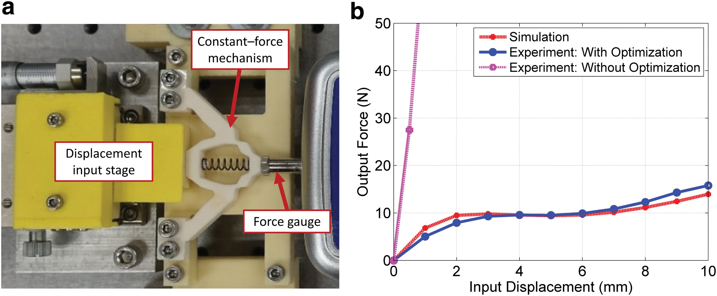
Measurement of the output force characteristic for the compliant constant-force mechanism.
Figure 7b shows the experimental result for the output force curve of the developed constant-force mechanism comparing with the simulation result. The overall trend of the experimental output force curve agrees well with simulation. The average difference between simulation and experiment results from 1 to 10 mm input displacement range is 10.5%. For the desired constant-force region (from 2 to 6 input displacement range), the average difference between simulation and experiment results is 6%. The discrepancy may be contributed by the effect of mounting, and difference from the numerical and exact material parameters. In addition, the geometric dimensions of the prototype might be slightly different from the numerical model due to the manufacturing tolerance in 3D printing.
The design domain structure (without optimization) as shown in Figure 3a is also prototyped, and placed in the experimental setup shown in Figure 7a to measure the output force profile; the experimental output force curve is shown in Figure 7b. The output force is quite large for the prototyped design domain structure; the output forces at input displacement of 1 and 2 mm are 69 and 141 N, respectively. For the optimized design, the experimental results show the developed constant-force mechanism can generate a nearly constant output force of 9.6 N in the input displacement range of 3–6 mm with a force variation ratio of 1.8% in average (and 3.1% in maximum).
Constant-Force Compliant Gripper
The developed compliant constant-force mechanism is used to design a constant-force gripper in this study. Figure 8a shows the prototype of the constant-force gripper mounted on a robot arm. The detailed design scheme of the gripper is shown in Figure 8b. It can be observed that the traditional rigid gripper jaw is replaced by the developed compliant constant-force mechanism installed on an electric gripper drive (TOYO CHS25) through an adapter. A DC motor is mounted on the adapter to drive a slider-crank mechanism to provide displacement input for the compliant constant-force mechanism. A gripping surface with a width of 2 mm, a height of 30 mm, and a thickness of 7 mm is introduced in front of the constant-force mechanism. During gripping operation, the electric gripper drive can drive the adapter to the location where the gripping surface is just before contact with the target object, then the DC motor can drive the compliant constant-force mechanism to be in contact with the target object, and provide a nearly constant gripping force.

Prototype of the constant-force compliant gripper mounted on a robot arm.
Figure 9 shows the gripping test results of a 3D printed polylactic acid (PLA) structure, which is with a width of 100 mm, a height of 40 mm, and a thickness of 7 mm. From Figure 9a, it can be observed that the PLA structure is deformed when using the design domain structure as shown in Figure 3a as the gripping jaws. However, The PLA structure is undeformed when using the prototyped compliant constant-force mechanism when using the same amount of input displacement, which also shows the effectiveness of the developed compliant constant-force mechanism. The input displacement for the conditions in Figure 9a and b are both equivalent to 16.5 mm from one side of the gripping jaw. The input displacement for Figure 9a is provided by the electric gripper drive only, whereas the input displacement for Figure 9b is provided by the electric gripper drive and the DC motor-driven slider-crank mechanism. The input displacement provided by the DC motor-driven slider-crank mechanism is 3 mm, and its effect can be compensated by the deformation of the constant-force mechanism.
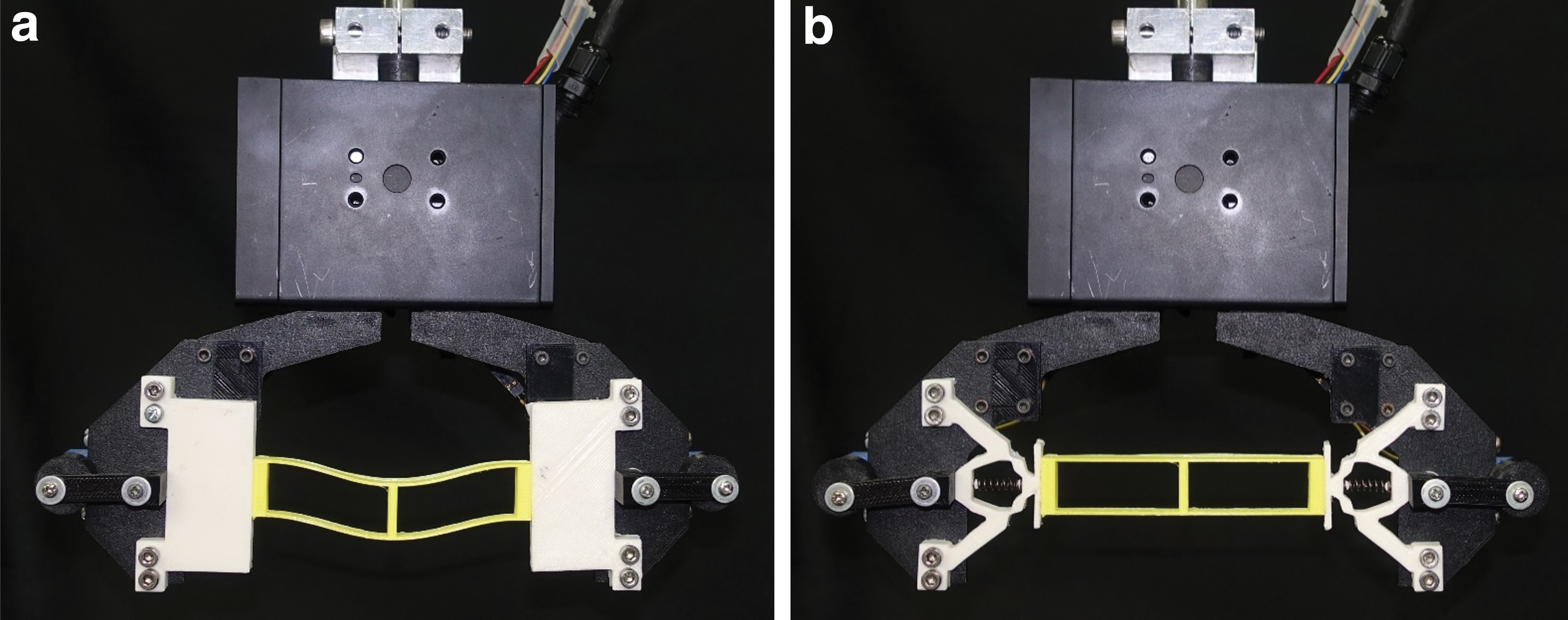
Gripping test results of a three-dimensional printed PLA structure.
Figure 10 shows a variety of different objects (including apple, balloon, plush toy, cup, hard disk drive, and tape) gripped by the developed constant-force gripper. The experimental results given in Figures 9 and 10 show the developed soft constant-force gripper can be used to pick and place a variety of objects (including deformable, fragile, and relatively rigid objects) without causing surface damages.

Gripping test results for a variety of different objects, including apple, balloon, plush toy, cup, hard disk drive, and tape, by the developed constant-force compliant gripper. Color images are available online.
Discussions
An optimal design procedure, including topology and geometry optimization methods, to synthesize a compliant constant-force mechanism is presented in this study. In topology optimization step, the numerical instability caused by mesh distortion of low-density elements in large deformation condition is resolved by introducing additional hyperelastic elements on original linear elastic elements when the pseudodensity of an element is smaller than a threshold value. This approach works because of the additional hyperelastic element introduces a more realistic stress–strain relation as well as it adds additional stiffness to an original linear elastic element. In geometry optimization step, a helical spring is introduced at the middle of the topology-optimized constant-force mechanism to replace the low-density elements at central region. So these low-density elements are eliminated in the geometry optimization step and their effect is accounted by the helical spring, which is one way to prevent to deal with numerical instability and physical prototype issues of low-stiffness elements.
The developed compliant constant-force mechanism works similar to a passive absorber, which can compensate the external disturbance within the desired input displacement range. When a displacement input is applied at the input port the body of the developed compliant constant-force mechanism deforms, whereas the output displacement at the output port can maintain nearly a same value when input displacement increases. So the external load can be absorbed by the deformation of the compliant constant-force mechanism, which makes its output force remains nearly a constant value for a window of input displacements. Without the need of additional sensors for output force control, the proposed compliant constant-force mechanism is a passive force regulation device that can be used to provide passive force control and overload protection for automation systems with low positioning accuracy.
The topology optimization method used in this study is limited to synthesis of compliant mechanisms that mainly consist of linear elastic material at high-density region. It would be desirable to develop an additional methodology that can consider mechanisms with fully hyperelastic and viscoelastic material properties. Different sets of boundary conditions and design parameters can lead to different designs. The boundary conditions and parameters of the developed compliant constant-force mechanism are chosen based on the design scheme of the proposed constant-force gripper. The proposed design can be further improved by testing of different sets of design schemes and parameters, which leads to a design with smaller force variation and larger constant-force range.
Conclusions
An optimal design procedure for synthesis of compliant constant-force mechanisms is presented in this study. An optimized constant-force mechanism design is identified numerically, then prototyped by 3D printing using flexible TPE. Experimental results show that the proposed design can generate a nearly constant output force of 9.6 N in the input displacement range of 3–6 mm with a force variation ratio of 1.8% in average (and 3.1% in maximum). Comparing with previous designs, the proposed method can be used to synthesize compliant constant-force mechanisms with smaller force variation in a larger motion range. The average difference between simulation and experiment from 1 to 10 mm input displacement range is 10.5%; for the constant-force range (from 3 to 6 mm), the average difference between simulation and experiment is 2.6%.
The output force of the developed constant-force mechanism is linear proportional to its thickness. By varying the thickness of the synthesized constant-force mechanism, the output force of the mechanism can be adjusted. The developed constant-force mechanism is installed on an electric gripper drive mounted on a robot arm for robotic picking and placing application. Test results show that the design can be used in handling of size-varied fragile objects. The outcome of this study provides numerical methods for synthesis of compliant constant-force mechanisms as well as the compact design of an innovative constant-force mechanism, which can deliver a nearly constant output force over a range of input displacements.
Footnotes
Author Disclosure Statement
No competing financial interests exist.
Funding Information
This study was supported by the grant, MOST 106-2221-E-006-096, from the Ministry of Science and Technology of Taiwan.